Note: Descriptions are shown in the official language in which they were submitted.
CA 02830832 2013-09-19
WO 2012/131146 PCT/F12012/000019
Method for cleaning drilling fluid in rock sampling drilling and a cleaning
unit
The invention relates to a method for cleaning drilling fluid in rock sampling
drilling, where a drilling machine is used, which has a hollow drilling pipe,
a blade
unit in the drilling end of the drilling pipe, a protective pipe, which
surrounds the
part of the drilling pipe which is close to the ground surface, so that there
is empty
space between the drilling pipe and the protective pipe, and in the method
drilling
fluid is fed into the drilling pipe, which drilling fluid lubricates the
drilling event, and
the drilling fluid flows between the drilling pipe and the wall of the drill
hole toward
the opening of the drill hole, simultaneously transporting solid matter formed
in the
drilling. The invention additionally relates to a cleaning unit for the
drilling fluid in
sampling drilling.
In ground and rock sampling drilling the aim is to obtain a sample bar from
the
_ ground or bedrock over the length of the entire drilling depth or a part of
it, which
sample bar is generally rock material from the bedrock or in some cases also
soil
from the ground. The product of the sampling drilling is thus a sample bar
raised
from the drill hole, which is arranged in sample boxes for example for
examination
by a geologist. The hole generated in the drilling itself is a by-product,
even if it
may also in some cases be utilised.
Sampling drilling differs from other ground drilling fields, such as oil
drilling,
charging drilling for blasting in the building trade, drilled well or heat
well drilling,
drilling of charging and guide holes in an ore body in mining, drilling gas
exhaust
holes in coal mines or holes made in rescue operations. In all these the aim
is to
drill a hole in the ground or bedrock, which is utilised in different ways in
each
field. The product of the operation is thus a hole achieved in the ground or
bedrock, and the rock material obtained from the drill hole is a by-product or
rather
waste, which is not utilised in any way. In these drillings all the soil or
rock material
from the drill hole is crushed and ground with the drilling blade into a quite
fine
material, which is removed as soil or rock mud with the aid of the drilling
fluid flow.
In sampling drilling on the other hand, soil and rock material is ground away
from
the ground and bedrock with a pipe-like blade only from a quite small,
circular
area. Thus a sample bar containing soil or rock material situated at each
drilling
depth remains inside the blade and drilling pipe, which sample bar is lifted
in parts
of a suitable length up from the drill hole and sorted for subsequent
examinations.
CA 02830832 2013-09-19
WO 2012/131146 PCT/F12012/000019
2
In sampling drilling a cylindrical hollow diamond blade placed in the end of a
drilling pipe is rotated and pressed with a suitable force against the rock.
The
power needed for rotating and pressing the blade and drilling pipes is
provided
with a drilling machine, which contains both a rotating unit and a power means
providing supply power. Inside the drilling pipe above the blade unit there is
a
separate core pipe, which adheres to the rock sample and with the aid of which
the rock sample can be lifted up from the hole by means of a device called a
retriever and a winch. The sample bar is lifted with the above-described
special
technology of the sample drilling field, which utilises a core pipe, a
retriever and a
=winch. Deep-reaching rock drilling is not possible to perform without using
drilling
fluid. Water obtained from nature close to the drilling site is usually used
as drilling
fluid, or it is brought to the site in a tank or a corresponding container. In
some
cases some other fluid than water can be used as the drilling fluid.
Without drilling fluid the tip of the diamond blade overheats and wears
quickly. On
the other hand when lubricated and cooled by drilling fluid, the diamond blade
lasts very long when used correctly. The drilling fluid also lubricates the
rotation of
the long drilling pipe inside the rock and removes rock material abraded from
the
rock, i.e. rock mud, away from the blade and finally out of the drill hole.
Quite a
little rock mud is formed in the case of sample drilling, because the amount
of rock
material abraded off the rock is much smaller than in other fields using
ground
drilling. Most of the rock material in the drill hole remains in the rock
material bar
formed as a product. Chemicals can, if necessary, be added to the drilling
water,
which further facilitate the drilling event and prolong the lifetime of the
blade,
which is prior art as such.
The drilling fluid lubricating the drilling event is with current technology
normally
taken from a lake, a ditch or some other natural water source located near the
drilling site. If necessary, water collecting in a previously drilled hole may
also be
utilised. The drilling fluid is fed with a suitable pressure inside the
drilling pipe and
down along the pipe, all the way to the blade rotating inside the rock. By the
drilling blade the drilling fluid lubricates the drilling event, cools the
blade and
removes rock material generated in the drilling, i.e. drilling mud. Thereafter
the
drilling fluid and the rock mud it contains flows back upwards outside the
wall of
the drilling pipe. The fluid and the drilling mud it contains flow upwards
between
the drilling pipe and the wall of the hole drilled in the rock, pushed by
fluid supply
pressure prevailing behind it. At the same time the fluid also lubricates the
rotation
of the drilling pipe in the hole formed in the rock. If the rock is very
fractured or
CA 02830832 2013-09-19
WO 2012/131146 PCT/F12012/000019
3
porous, some drilling fluid is absorbed into cracks and pores in the rock.
This is
illustrated in Figure 4.
When the drilling fluid gets through the drilling hole drilled in the rock and
arrives
at the layer of soil between the rock and the ground surface, it travels
inside the
protective pipe plunged into the soil layer, the so-called soil pipe, upwards
to the
ground surface. With the aid of the protective pipe the excessive absorption
of
fluid into the soil material between the ground surface and the rock is
avoided.
The protective pipe extends somewhat above the ground surface, and its end is
situated underneath or inside the drilling machine. This is shown in Figure 3.
With current technology the drilling fluid rising from the protective pipe and
the
possible chemicals it includes and the solid matter, which is rock, soil,
metal
particles detached from the drilling equipment and other fine solid matter,
flow
from the opening of the protective pipe underneath the drilling machine and
further
= into the surrounding terrain.
When rising from the ground the drilling fluid is even in winter clearly warm.
The
drilling fluid rising from the protective pipe and flowing from underneath the
machine to the terrain may in places cause a muddy area which causes soiling
of
machines, clothes and equipment and which encumbers movement of the crew,
and additionally in winter the freezing of the drilling fluid causes a risk of
slipping,
which are work safety risks. In winter time drilling may be done on the ice of
a lake
or on a frozen swamp, whereby the ice or frozen surface of the swamp supports
the drilling machine. The flow of drilling fluid into the area surrounding the
machine
melts the ice or frozen swamp supporting the machine and may cause the
machine to sink, which is also a great work safety risk.
Because the initial drilling fluid is usually taken from a natural water
source, it must
in sub-zero weather be heated immediately after taking it from the water
source,
for which a lot of energy is used. If the drilling fluid is not heated, there
is at least
in very low temperatures and with long water lines a risk of the drilling
fluid lines
freezing. When a drilling fluid line freezes the drilling operation is
immediately
interrupted.
In some cases chemicals must be added to the drilling fluid, which chemicals
assist the drilling event. After use the fluid equipped with chemicals flows
back into
the environment, whereby in addition to having to continuously use quite a lot
of
additional substances, chemicals added to the fluid also end up in the
CA 02830832 2013-09-19
WO 2012/131146 PCT/F12012/000019
4
environment. Even though these chemicals are with current knowledge not
regarded as dangerous for the environment, the applicant company has due to a
high environmental awareness paid attention to the matter.
Patent publication US2008/121589 discloses a fluid cleaning apparatus for
cleaning drilling fluid so that the fluid could be used again in drilling.
This has
several successive precipitation basins, between which there are weir walls,
which
get lower in successive precipitation basins. These weir walls are arranged so
that
turbulences in the basins are minimised. Such an arrangement, however, makes
the removal of fine material from the drilling fluid difficult and in sampling
drilling
the solid matter in the drilling fluid is mostly fine.
Patent publication EP 0047347 discloses a closed circulation system for
drilling
fluid. The drilling operation described in said reference publication is
however
related to drilling for coal deposits done in coal mines, which drilling only
occurs
underground and substantially in the horizontal direction. The aim is to drill
a hole,
which is a few hundred meters long, into a coal deposit, the purpose of which
hole
is to remove methane gas in a controlled manner from a future mining area.
Thus
the coal mining later done in the vicinity of the hole would be safer. The
technology described here contains a complicated processing apparatus for
drilling fluid, which apparatus substantially makes possible the separation of
explosive methane gas from fluid and its safe removal. The described apparatus
is based on a very complicated technology, where successive sedimentation
basins arranged in closed and gastight spaces, optimal boundaries for gas and
fluid, which in different basins are at different levels, a screw conveyor
used for
removing rock material and centrifugal separation used for removing finer rock
material and different pumps, systems used for separating fluid, gas and rock
material are utilised.
Patent publication WO 99/15758 discusses the use of a closed drilling fluid
circulation system. Here the drilling occurs only in sea areas, for example in
connection with oil drilling. The described technology includes a very
complicated
cleaning system placed at the bottom of the sea, which system only performs
removal of coarse rock material. The aim thereof is that the wear of pumps and
other technology can be reduced and the reliability of the technology is
improved
in Offshore conditions.
Patent publication US 5928519 describes the use of a closed drilling fluid
circulation system in connection with under-balanced drilling (UBD) in oil and
gas
CA 02830832 2013-09-19
WO 2012/131146 PCT/F12012/000019
drilling. UBD drilling differs from normal oil drilling in that no
overpressure prevails
in the drilling fluid in the drill hole and pipe system, but an underpressure
is
provided in the drilling pipe system with the aid of suction occurring from
the
drilling fluid outlet side. This in some cases provides definite advantages,
such as
5 the fact that the risk of deterioration of the oil deposit is reduced and
the risk of the
drilling pipe getting stuck in the hole is reduced. Two different closed
pressure
containers are needed for circulating the drilling fluid, which both contain
complicated technology. One container has a higher pressure and the other a
lower pressure.
Patent publication US 5454957 describes the use of a closed drilling fluid
circulation system in connection with oil drilling, where diesel, mud/drilling
mud
and fine particles are separated from the drilling fluid. An arrangement for
closed
circulation is here presented, where very complicated technology is used,
including agitators, activated sludge tanks, soil and rock mud washers, mud
dryers, intermediate storing tanks for sludge, centrifuge/sling separators,
fluid
traps, fluid processing devices, diesel separators and tanks, pumps and
conveyors. The methods described for recycling the drilling fluid require very
complicated apparatuses, the moving of which from one place to another is
practically impossible.
Generally in sampling drilling the amount of used drilling fluid and the
amount of
fine solid matter formed in the drilling is significantly smaller than with
other rock
drilling methods. Thus a reason for recycling the drilling fluid has
traditionally not
been seen. Thus the ways of cleaning drilling fluid for recycling in other
drilling
methods are also quite difficult to apply to sampling drillings.
An object of the invention is a solution by which the drawbacks and
disadvantages
relating to the prior art can be considerably reduced.
The objects of the invention are attained with a method and a cleaning unit,
which
are characterised in what is presented in the independent claims. Some
advantageous embodiments of the invention are presented in the dependent
claims.
The main idea of the invention is to recover the drilling fluid used in sample
drilling
at a drilling machine, when the drilling fluid exits the drill hole, and to
transport it to
a separate cleaning unit. The cleaning unit has two or more precipitation
basins,
CA 02830832 2013-09-19
WO 2012/131146 PCT/F12012/000019
6
where solid matter is separated from the drilling fluid. The cleaned drilling
fluid is
returned to the drilling machine and reused in sample drilling.
The method according to the invention for cleaning drilling fluid in rock
sampling
drilling comprises using a drilling machine, which has a hollow drilling pipe,
a
cylindrical blade unit in the drilling end of the drilling pipe, a protective
pipe, which
surrounds the part of the drilling pipe which is close to the ground surface,
so that
there is empty space between the drilling pipe and the protective pipe, and in
the
method drilling fluid is fed into the drilling pipe, which drilling fluid
lubricates the
drilling event, and the drilling fluid flows between the drilling pipe and the
wall of
the drill hole toward the opening of the drill hole, simultaneously
transporting
powder-like solid matter formed in the drilling. The method further has steps,
where the drilling fluid coming from between the protective pipe and the
drilling
pipe in the drilling machine and containing solid matter is recovered with an
arrangement in the drilling machine, the recovered drilling fluid is guided to
a
cleaning unit, which cleaning unit has at least two precipitation basins,
where solid
matter is separated from the drilling fluid and the drilling fluid cleaned in
the
cleaning unit is guided to the drilling machine and fed into the drilling
pipe. Of the
precipitation basins at least two are in series, i.e. the fluid to be cleaned
passes in
order from one basin to the next. Uncleaned drilling fluid is fed into the
first
precipitation basin and cleaned drilling fluid is removed from the last
precipitation
basin. Between the precipitation basins there is a transfer connection, which
has
an intake end and a discharge end. The intake end takes fluid from the
precipitation basin and the discharge end discharges the fluid into the next
precipitation basin. The discharge ends of the transfer connections are closer
to
the bottom of the basins than the intake ends.
In one embodiment of the method according to the invention drilling fluid
sludge
containing solid matter accumulating on the bottom of the precipitation basin
is
removed from the basin. The drilling fluid sludge contains solid matter to a
significantly higher degree than the uncleaned drilling fluid. In a second
embodiment of the method according to the invention the drilling fluid sludge
accumulating on the bottom of the precipitation basin and containing solid
matter
is filtered and returned to some precipitation basin.
In a third embodiment of the method according to the invention the drilling
fluid is
in the cleaning unit fed into the first precipitation basin through a nozzle,
which
nozzle has a throat part and a curved flange part, and the curved flange part
is
CA 02830832 2013-09-19
WO 2012/131146 PCT/F12012/000019
7
arranged so that the fluid flow substantially follows the flange part and
solid
matters contained in the fluid detach from the flow.
In a fourth embodiment of the method according to the invention an ion charged
polymer mixture, ferrous sulphate, ferric sulphate or some other chemical
added
to the drilling fluid, which assists the separation of solid matter from
fluid, is used
in the cleaning of the drilling fluid for boosting the process.
In a fifth embodiment of the method according to the invention new drilling
fluid is,
when necessary, added to the drilling fluid circulation.
In a sixth embodiment of the method according to the invention substances or
chemicals which assist the drilling process are added to the drilling fluid
before the
drilling fluid is returned to the drilling pipe.
In one embodiment of the method according to the invention the cleaning unit
is
placed in one or more containers or other movable structures. The walls of the
structure are thermally insulated, and a heating device may be installed
therein.
The cleaning unit for drilling fluid in sampling drilling according to the
invention has
a connection for feeding uncleaned drilling fluid into the cleaning unit, at
least two
precipitation basins, where solid matter contained in the drilling fluid is
arranged to
accumulate on the bottom of the basin, where it forms drilling fluid sludge,
and in
the bottom part of at least one precipitation basin there is a valve
arrangement for
removing said drilling fluid sludge containing solid matter from the
precipitation
basin, and between the precipitation basins there is a transfer connection for
moving the drilling fluid between precipitation basins and in the last
precipitation
basin of the series there is an outlet connection for removing the cleaned
drilling
fluid from the cleaning unit. The transfer connections have an intake end and
a
discharge end and the discharge ends of the transfer connections are closer to
the bottom of the precipitation basins than the intake ends. The cleaning unit
is
placed in one or more container or corresponding structure meant to be moved.
In one embodiment of the cleaning unit according to the invention the drilling
fluid
sludge let through the valve arrangement and containing solid matter is
arranged
to travel through a filter arrangement for separating the solid matter.
In a second embodiment of the cleaning unit according to the invention the
filter
arrangement can be detached for replacement or cleaning or it can be cleaned
in
its place. In a third embodiment of the cleaning unit according to the
invention
CA 02830832 2013-09-19
WO 2012/131146 PCT/F12012/000019
8
there is a point in the bottom of the precipitation basin which is lower than
the rest
of the bottom, wherein the drilling fluid sludge is arranged to accumulate.
The
valve arrangement is placed in this point. In a fourth embodiment of the
cleaning
unit according to the invention the drilling fluid separated from the drilling
fluid
sludge with the filter arrangement is arranged to be transported back to the
precipitation basin.
In a fifth embodiment of the cleaning unit according to the invention there is
a
lower basin beneath the precipitation basin or precipitation basins, in which
lower
basin the drilling fluid separated from the drilling fluid sludge with the
filter
arrangement or filter arrangements is arranged to be collected and from which
lower basin there is a transfer arrangement for moving the drilling fluid to
the
precipitation basin.
In a sixth embodiment of the cleaning unit according to the invention the
uncleaned drilling fluid fed into the first precipitation basin is arranged to
be fed
through a nozzle (611), which nozzle has a throat part and a curved flange
part,
and the curved flange part is arranged so that the fluid flow substantially
follows
the flange part and the solid matters contained in the fluid detach from the
flow.
In a seventh embodiment of the cleaning unit according to the invention the
discharge ends of the transfer connections between the precipitation basins
are
closer to the bottom of the basin than the intake ends and the discharge ends
are
formed to guide the drilling fluid substantially toward the bottom of the
precipitation
basin.
In an eight embodiment of the cleaning unit according to the invention an ion
charged polymer mixture, ferrous sulphate, ferric sulphate or some other
chemical, which assists the separation of solid matter from fluid, is arranged
to be
added to the drilling fluid. In a ninth embodiment of the cleaning unit
according to
the invention it has an arrangement for feeding substances, which assist the
drilling event, into the drilling fluid before the drilling fluid is returned
to the drilling
process.
An advantage of the invention is that with its aid, work safety risks can be
reduced
in sample drilling operation. The risk of slipping is reduced, because only
very little
water, if any at all, flows beneath the drilling machine. The drilling water
causes a
risk of slipping, except in the winter when freezing, also in the summer,
especially
if slippery drilling assisting chemicals are used in the fluid.
CA 02830832 2013-09-19
WO 2012/131146 PCT/F12012/000019
9
It also helps the drilling machine to move in the environment. Without
recycling of
the drilling fluid a lot of water flows into the terrain surrounding the
drilling
machine, and the roads surrounding the machine unavoidably become muddy
before long. This causes work safety risks when movement becomes more
difficult, especially when the crew must carry equipment needed in the
drilling,
such as drilling pipes and rock samples, when moving around the machine. When
recycling drilling fluid these problems are reduced, because the area around
the
machine remains dry. The soiling of the crew's clothes and the inner parts of
the
machine is thus also avoided.
A further advantage of the invention is that energy is saved with its aid.
With
traditional technology the drilling water must in wintertime continuously be
heated,
in order to avoid freezing of the fluid lines. When using initial fluid taken
from a
ditch or lake with traditional technology, a lot of energy has to be used for
heating
the fluid. Correspondingly very warm drilling water returning from under the
ground
is in the traditional method poured into the ground after use, and the thermal
energy it contains is lost. In winter the heat of the drilling fluid rising
from the
ground can when recycling be utilised, whereby a significant amount of energy
is
saved.
The invention further intensifies sampling drilling, because it reduces the
risk of
freezing of the drilling fluid lines in the winter. With the traditional
technology the
drilling operation must immediately be interrupted when the drilling fluid
lines
freeze or when the water supply otherwise is interrupted, until water is again
obtained to the process. When using the invention, even if the line of the
initial
replacement water should freeze, the crew would, due to the large amount of
fluid
in circulation, have plenty of time to repair the lines without having to
interrupt the
drilling operation. If the drilling operation is for some reason interrupted,
the initial
drilling fluid must with the traditional technology still be allowed to
continuously
circulate in vain in order to prevent freezing and the fluid must be allowed
to flow
to waste as unused. In some cases even all intermediate fluid storages must be
emptied in vain due to the risk of freezing. Because in winter the drilling
fluid rising
from the ground is very warm, this heat can in the case according to the
invention
be utilised, whereby interruptions in the drilling due to other reasons can
even be
quite long, without there being a risk of the fluid freezing.
An advantage of the invention is also that it saves water or other used
drilling fluid.
In some places finding drilling water can be difficult or the water must be
led to the
drilling site even from far away. According to the invention the same drilling
fluid
CA 02830832 2013-09-19
WO 2012/131146 PCT/F12012/000019
always circulates in the drilling operation, and it needs to be added only for
example for compensating evaporation and fluid absorbed into cracks in the
rock
or into the ground from the boundary of the protective pipe.
An advantage of the invention is still that the used chemicals do not flow
into the
5 environment in an uncontrolled manner. Chemicals, which facilitate the
drilling
operation, must in certain situations be added to the drilling fluid.
According to the
traditional technology these chemicals continuously flow into the environment.
Even though these chemicals are according to current knowledge not harmful for
the environment, it is better that substances are not let into the
environment,
An advantage of the invention is also that with its aid, a large part of the
rock mud
from the drilling hole is recovered. As of now, this mass has no practical
use, but
when it is in accordance with the invention begun to collect, it may be
utilised over
In the following, the invention will be described in detail. In the
description,
reference is made to the enclosed drawings, in which
Figure 2 shows as an example a cross section of an arrangement according to
the invention for collecting drilling fluid,
Figure 3 shows as an example a drilling pipe and a protective pipe,
Figure 4 shows as an example a drilling pipe,
Figure 6 shows as an example the inner structure of a cleaning unit according
to
the invention,
CA 02830832 2013-09-19
WO 2012/131146 PCT/F12012/000019
11
Figure 7 shows as an example a longitudinal cross section of a cleaning unit
according to the invention,
Figure 8a shows as an example a nozzle used in one embodiment of the
invention,
Figure 8b shows the fluid and solid matter flows caused by the nozzle of
Figure
8a and
Figure 9 shows as an example an arrangement according to the invention for
collecting drilling fluid.
Figure 1 shows as an example a drilling machine 100 for sample drilling. The
drilling machine has a drilling pipe 101 and a drilling unit 102, with which
the
movement needed for the drilling is produced. The drilling machine has a
frame,
which supports the structures of the drilling machine. The frame has
arrangements, with which the angle of the drilling pipe and simultaneously the
angle of the drill hole are adjusted. In the case according to the figure the
drilling
machine is one the ground surface 103, but it can be placed for example on a
raft
or in a mine. In sample drilling the aim is usually to obtain rock samples
from the
bedrock. The rock 105 is usually covered by a layer of soil 104. The drilling
machine has an arrangement, with which drilling fluid is fed into the drilling
pipe.
Points B, C and D are marked in the figure, which points are presented in more
detail in Figures 4,3 and 2.
Figure 2 shows an arrangement according to the invention for collecting
drilling
fluid as a cross section. The arrangement has a drilling pipe 101, a
protective pipe
201, a collecting collar 202 and a collecting basin 203. The drilling pipe is
hollow,
and the drilling unit rotates it. The protective pipe is around the drilling
pipe so that
it extends substantially through the soil layer and its end toward the
drilling
machine is above the ground surface. The drilling fluid returning from the
drilling
process, which rises from a gap between the protective pipe and the drilling
pipe,
is collected with a collecting collar situated around the end of the
protective pipe
and guided to the collecting basin. The collecting basin is attached either to
the
machine or with a joint to the protective pipe. The collecting basin is shaped
and
placed so that the position of the drilling can be moved at least in the
commonly
used drilling angles, i.e. in a 30-90 angle in relation to the horizontal
plane, and
that the drilling fluid coming from the protective pipe ends up in the
collecting
basing regardless of the position of the drill. The movement seam between the
CA 02830832 2013-09-19
WO 2012/131146 PCT/F12012/000019
12
protective pipe and the collecting basin can, if necessary, be tightened for
example with a tightener manufactured from tarpaulin or a flexible rubber,
which
allows the necessary movement area of the drill and guides the drilling fluid
coming from the protective pipe at least almost completely into the collecting
basin. From the collecting basin the drilling fluid and the solid matter it
contains,
such as soil and rock mud, and possible drilling additives, are guided into a
cleaning unit, which can be moved in the terrain.
Figure 9 shows a second example of an arrangement according to the invention
for collecting the drilling fluid in a drilling machine. The arrangement has a
protective pipe 903, a collecting collar 904 and a collecting basin 905. The
collecting collar has a hole 901 for the drilling pipe. The water coming from
the
protective pipe is collected with the collecting collar and guided to the
collecting
basin. The collecting basin has a pipe 902, with which the uncleaned drilling
fluid
is removed from the collecting basin and guided with some arrangement into the
cleaning unit.
Figure 3 illustrates the placement of the protective pipe 201 in the sample
drilling.
The drilling pipe 101 has been used to drill a sampling hole from the ground
surface 103 through the soil layer 104 into the rock 105. In the case
according to
the figure the protective pipe extends through the soil layer some way into
the
rock. The drilling fluid rising between the wall of the drill hole and the
drilling pipe
mostly goes between the protective pipe and the drilling pipe and continues to
rise.
Figure 4 shows the drilling end of the drilling pipe 101 inside the rock 105.
In the
end of the drilling pipe there is a cylindrical blade part 401, which when it
rotates
drills a rock sample bar 402 from the rock. Inside the drilling pipe there is
a core
pipe 403, inside which the rock sample bar goes. With the core pipe the rock
sample bar can be lifted to the ground surface and stored. The drilling fluid
gets to
the blade part between the core pipe and the inner wall of the drilling pipe.
As a
difference to other drilling fields, only a little rock mud accumulates in the
drilling
fluid in sampling drilling, because the blade used in the drilling grinds away
only a
small part of the area of the drill hole. The largest part of the rock
material remains
in the rock sample bar generated as a product of the drilling operation, which
rock
sample bar is traditionally according to prior art lifted with a core pipe up
from the
drill hole.
CA 02830832 2013-09-19
WO 2012/131146 PCT/F12012/000019
13
Figure 5 shows an arrangement according to the invention for cleaning and
reusing drilling fluid in sample drilling, which arrangement has a drilling
machine
100 and a cleaning unit 501 for cleaning the drilling fluid. The drilling
machine is
used to drill a drill hole for taking samples from the bedrock. The drilling
machine
has a drilling pipe 101 and a collecting basin 203 which collects drilling
fluid
coming from the drill hole during drilling. From the collecting basin the
drilling fluid
is led with a pipe 502 for uncleaned drilling water to the cleaning unit. If
necessary,
pressure is provided in the pipe with a pump 503. Because the drilling fluid
does
not contain a very large amount of solid matter, it is very fluid, and a pump
is not in
all cases necessary needed for transferring the drilling fluid from the
collecting
basin to the cleaning unit. If the drilling machine is higher in the terrain
than the
cleaning unit, the drilling fluid can be allowed to flow along a sufficiently
large pipe
with the aid of gravity. If necessary, a suitable pump is still used for
ensuring the
transfer of the fluid.
The cleaning unit 501 may be some thereto suitable structure, such as for
example a container, a wagon or a vehicle, inside which the apparatus needed
for
the cleaning is placed. This container, wagon or vehicle or other structure is
on the
other hand placed in the terrain in the vicinity of the drilling machine 100,
and
when the drilling site is moved it can be moved along with the drilling
machine
either with the aid of another vehicle or with its own power of movement. The
cleaning unit has means, with which its position can be adjusted as desired,
even
if the ground surface it stands on is uneven. The cleaning unit contains
either just
an apparatus needed for cleaning fluid or additionally also an apparatus used
for
blending chemicals needed in the drilling process into the drilling fluid.
Because
the apparatus needed for blending chemicals is not used in every drilling
site, it
may be advantageous to place the apparatus for blending chemicals in its own
separate movable container, wagon or vehicle. Whether the apparatus for
blending chemicals is placed in the same space or in a different space than
the
apparatus for cleaning drilling fluid, they are arranged so that they can
according
to need either both be used at the same time or each of them separately. From
the cleaning unit the cleaned drilling fluid is brought to the drilling
machine with a
pipe 504 for cleaned drilling fluid. At the drilling machine the cleaned
drilling fluid is
fed back into the drilling pipe.
Even though the drilling fluid circulating in the drilling process stays warm
during
the drilling operation even in winter due to the ground heat of the drill hole
and the
friction caused by the rotation of the drilling blade and the pipes, there is
during
CA 02830832 2013-09-19
WO 2012/131146 PCT/F12012/000019
14
winter a risk that the drilling fluid freezes mostly in situations, where the
drilling
operation is stopped for a long time. Therefore the cleaning system for
drilling fluid
is placed in a structure, the walls of which are thermally insulated, if it is
used in
winter conditions. Sufficient heating is also arranged inside the structure,
so that
the fluids and devices it contains do not freeze in sub-zero weather if the
drilling
operation is interrupted.
Figure 6 shows the inner structure of a cleaning unit according to the
invention.
The cleaning apparatus according to the example has four precipitation basins:
a
first precipitation basin 604, a second precipitation basin 605, a third
precipitation
basin 606 and a fourth precipitation basin 607 and a lower basin 608 beneath
these. There are at least two basins. The drilling fluid to be cleaned is
guided into
the first precipitation basin with a nozzle 601. Between the precipitation
basins
there are transfer connections 610. For removing the cleaned drilling fluid
from the
cleaning unit there is an outlet connection 611. In the bottom of each
precipitation
basin there is a valve arrangement, which can be used to let drilling fluid
sludge
accumulating at the bottom of the precipitation basins out of the
precipitation
basin. A filter arrangement 609 for the drilling fluid sludge is attached to
the calve
arrangement. An evacuation pipe 602 for the lower basin is connected to the
lower
basin, which evacuation pipe has a pump 603.
The precipitation basins of the cleaning apparatus are shaped so that the
solid
matter contained in the fluid separates from the fluid and sinks to the bottom
of
the precipitation basin, forming drilling fluid sludge. The uncleaned drilling
fluid is
brought into the first precipitation basin 604 through a nozzle 601. This may
for
example be a Coanda type nozzle, with which the fluid part and solid matter
parts
of the drilling fluid are set into motion in different directions. The solid
matter is
directed so that it ends up on the bottom of the first precipitation basin.
From the
first precipitation basin the drilling fluid moves with a transfer connection
610 to
the second precipitation basin 605. The transfer connection is placed so that
the
drilling fluid is removed from the top part of the precipitation basin. If
necessary,
several successive precipitation basins can be used, whereby the fluid is
moved to
a new precipitation basin, where the same process occurs again. When several
precipitation basins are used in succession, drilling mud and solid matter is
mostly
accumulated in the first precipitation basin, and thereafter the drilling
fluid may still
be somewhat turbid. The amount of solid matter in the drilling fluid decreases
and
the drilling fluid is cleared up as it advances from one precipitation basin
to
another. Precipitation basins are placed in the cleaning unit in such a
number, that
CA 02830832 2013-09-19
WO 2012/131146 PCT/F12012/000019
the drilling fluid in the last precipitation basin is sufficiently clean, so
that it can be
used again in drilling. In the example according to the figure the
precipitation
basins are placed in succession, but their position may also be some other.
They
may be adjacent to each other, in succession or in several rows.
5 If necessary, a small amount of a polymer solution with a suitable ionic
electric
charge, ferrous sulphate or ferric sulphate, which are commonly used in
connection with for example waste water cleaning and sludge drying, may be
added to the drilling fluid in some precipitation basin, which substances when
mixed with water cause so-called coagulation and/or flocculation, i.e. an
10 electrochemical reaction, where solid matters in the water bind together
as larger
particles, which assists the separation of solid matter from the water and its
flowing to the bottom of the precipitation basin a drilling fluid sludge.
Underneath the precipitation basins is placed a detachable mechanical filter
arrangement 609 based for example on filter cloth, by means of which most of
the
15 solid matter contained in the drilling fluid sludge removed from the
bottom of the
basin is separated therefrom. Most of the drilling fluid sludge flows through
the
filter arrangement. Solid matter left inside the filter arrangement can be
removed
by detaching the filter arrangement. The filter arrangement can either be
disposable or such that is can be emptied from solid matter, washed and
reused.
The moist solid matter mass obtained with the aid of the filter arrangement
can, if
necessary, be stored either in the filter itself or for example in a separate
vessel,
such as a plastic bottle, if the solid matter should in the future for example
obtain a
work site-specific purpose related to sampling.
The drilling fluid separated from the drilling fluid sludge with the filter
arrangement
609 is poured into the lower basin 608, from where it at times is transferred
back
into some precipitation basin via the evacuation pipe 602 of the lower basin.
In the
example according to the figure the pipe has a pump 603 and it leads to the
first
precipitation basin 604. If the filter arrangement can be cleaned and reused,
the
filter cloth of the filter arrangement can be washed after the filter
arrangement is
emptied for example with water contained in either the lower basin or the
precipitation basin.
When the drilling fluid has been sufficiently cleaned in the precipitation
basins,
chemicals assisting the drilling process are, if necessary, added thereto in a
chemical mixing apparatus, which contains at least two successive basins. In
the
first basin, which may be smaller, a necessary amount of a desired chemical is
CA 02830832 2013-09-19
WO 2012/131146 PCT/F12012/000019
16
mixed into the drilling fluid, and in the second basin, which may be larger,
there is
a sufficient intermediate storage for drilling fluid, so that the drilling
operation can
take place continuously, without disturbances from the possible cyclic nature
of
the drilling fluid cleaning or the chemical addition process. The apparatus
arranged for adding chemicals is placed either in the same space as the
cleaning
apparatus or if necessary in its own separate space, which is transported to
the
drilling site only when needed. In the example according to Figure 6 the third
precipitation basin 606 may function as a chemical mixing basin and the fourth
precipitation basin 607 as an intermediate storage for drilling fluid. When
adding
chemicals the pH value of the drilling fluid is also measured, because the
dosing
of drilling assisting chemicals may depend on the pH value and some chemicals
do not mix in to the drilling fluid or function in a desired manner, if the pH
value is
wrong. The measured pH value of the drilling fluid can be changed as desired
by
adding chemicals which adjust pH value to the drilling fluid.
The drilling machine suctions the drilling fluid it needs for drilling for
example
either from the last precipitation basin of the cleaning unit or from the last
intermediate storage basin of the chemical mixing apparatus. Thereafter the
cleaned and treated drilling fluid is brought to the drill hole and it returns
after
having been at the drill blade along the drill hole and protective pipe back
to the
drilling machine, where it again flows to the collecting basin waiting by the
opening
of the protective basin and starts a new treatment cycle.
Some of the drilling fluid is lost despite the circulation, for example due to
evaporation of the warm water, absorption into the fractured bedrock, loss
occurring at the boundary between the protective pipe and the rock or loss
occurring in connection with the removal of solid matter from the basin. This
is
compensated with a traditional method, by taking substituting initial fluid
from a
natural water source or from a previous drill hole or a tank vehicle or the
like. The
new drilling fluid can be added to the drilling process at the drilling
machine or the
cleaning unit has an arrangement, for example a coupling, which is in
connection
with some precipitation basin, with which the new drilling fluid is added to
the
circulation of drilling fluid.
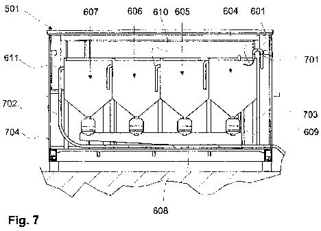
Figure 7 shows a longitudinal cross section of a cleaning unit 501 according
to the
invention, which has a cleaning apparatus according to Figure 6. The cleaning
apparatus is placed inside a frame 704. The frame is sufficiently sturdy for
transport and moving and it has necessary hatches, doors, ventilation openings
and the like. The walls of the frame are sufficiently thermally insulated in
relation
CA 02830832 2013-09-19
WO 2012/131146 PCT/F12012/000019
17
to the use environment of the cleaning unit. For example the walls of a
cleaning
unit intended for winter use are very thermally insulated, but for a cleaning
unit
adapted for mine use compactness and a small size are more useful. Inside the
frame there are also necessary arrangements for the driving force of the
cleaning
apparatus. These are motors, batteries, wirings and the like. Advantageously
all
the connections of the cleaning unit, the intake and outlet of drilling fluid,
the
addition of new drilling fluid, the electric wires and the like, can be
detached and
protected for when the cleaning unit is moved. The cleaning unit has
adjustment
means, such as adjustment legs, with which the position of the cleaning unit
can
be adjusted. With these adjustment means it is striven to hold in the designed
position regardless of the tilting of the terrain or the shape of the ground
surface.
This position is advantageously the horizontal position.
The drilling fluid to be cleaned is brought to the cleaning unit 501 with an
inlet pipe
701, which is in contact with the nozzle 601. The nozzle may be a Coanda type
nozzle. The inlet pipe has a suitable pressure, so that the fluid flow arrives
at the
nozzle with the correct speed. This pressure can be adjusted for example with
valves.
The four precipitation basins of the cleaning apparatus: the first
precipitation basin
604, the second precipitation basin 605, the third precipitation basin 606 and
the
fourth precipitation basin 607, are shaped to have a conical bottom or so that
some part of the bottom is lower than the rest of the bottom and the shapes of
the
bottom slant toward this part. The precipitation basins may be open or they
may
have lids. Between the precipitation basins there is a transfer connection 610
for
transferring drilling fluid from one precipitation basin to another. The
transfer
connection takes the drilling fluid from the top part of the precipitation
basin. The
intake opening of the transfer connection determines the upper surface of the
fluid
in the precipitation basin, because the drilling fluid always flows to the
next
precipitation basin, when the fluid surface rises to the intake opening. The
intake
openings of the transfer connections can between different precipitation
basins be
at different heights, whereby the fluid surfaces are at different heights in
different
precipitation basins. In the case shown in the figure the transfer connection
is a
pipe, which guides drilling fluid coming from the previous precipitation basin
towards the bottom of the precipitation basin. The discharge end of the pipe
is
substantially lower than its intake end in the precipitation basin. Because
the fluid
fow through the transfer connection is quite slow, the solid matter contained
in the
drilling fluid has time to sink to the bottom of the precipitation basin.
CA 02830832 2013-09-19
WO 2012/131146 PCT/F12012/000019
18
In the bottom of the precipitation basins, substantially at their lowest
point, there is
a valve arrangement 703. This is in connection with the filter arrangement 609
so
that the valve arrangement can, when necessary, be opened, and drilling fluid
sludge on the bottom of the precipitation basin, which contains a lot of solid
matter, can be let though the filter arrangement. The opening of the valve
arrangement can be done manually or automatically. Because solid matter is
accumulated in different precipitation basins at different rates, for example
precipitation matter is accumulated faster in the first precipitation basin
604 than in
the fourth precipitation basin 607, the valve arrangements of the
precipitation
basins are opened at different times. The filter arrangements can also be
different
in different precipitation basins. The drilling fluid separated from the
drilling fluid
sludge with the filter arrangement goes into the lower basin 608, which may be
an
open or closed container. From here the drilling fluid is led back to the
filtering
basin. The fourth, last, precipitation basin 607 has an outlet connection 611,
which
is in connection with an evacuation pipe 702 for cleaned drilling fluid, with
which
the drilling fluid is returned to the drilling machine.
Figures 8a and 8b show a nozzle 800, which uses the Coanda phenomenon. It
has an inlet part 801, a throat part 803 and a curved flange part. In the
Coanda
phenomenon a flow of fluids and gases occurring near a solid surface has a
tendency to follow the shape of the solid surface, even if the direction of
the
surface changes in relation to the direction of the flow. When the nozzle is
shaped
in the correct way, the direction of the fluid flow can be changed so quickly
that the
solid matters contained in the fluid detach from the flow and efficiently
separate
from the fluid. The inlet part is connected to the pipe bringing uncleaned
drilling
fluid to the cleaning unit. The throat part is shaped so that the flow rate of
the
drilling fluid passing through it can be made such that the Coanda phenomenon
occurs in the curved flange part, where the drilling fluid starts to follow
the surface
of the flange part. Thus the flow of drilling fluid undergoes a sudden change
in
direction based on the Coanda phenomenon, where the solid matter contained in
the drilling fluid efficiently detaches from the fluid flow immediately as it
arrives in
the precipitation basin and where the flow rate of the fluid thereafter
quickly
decreases. The location of the nozzle is selected so that the drilling fluid
flow
turned with the nozzle is close to the level of the fluid surface of the
precipitation
basin and substantially in the direction thereof. Depending on the case the
flow of
drilling fluid may also be slightly diagonally upwards or diagonally downwards
in
relation to the fluid surface. The direction of the solid particles is
substantially
toward the bottom of the precipitation basin. This is shown in Figure 8b,
where the
CA 02830832 2013-09-19
WO 2012/131146 PCT/F12012/000019
19
fluid flow follows the curved flange and the solid matter particles separate
from the
fluid flow. The flow occurring on the fluid surface of the precipitation basin
is slow
immediately after detaching from the nozzle. The fluid transfers to a transfer
connection located at the second edge of the precipitation basin, whereby
solid
matter possibly still remaining in the drilling fluid has time to sink further
and
separate from the slow flow occurring on the upper surface of the fluid in the
precipitation basin.
Some advantageous embodiments according to the invention have been
described above. The invention is not limited to the solutions described
above, but
the inventive idea can be applied in numerous ways within the scope of the
claims.