Note: Descriptions are shown in the official language in which they were submitted.
CA 02831012 2013-09-23
RUBBING MACHINE AND ITS TOOL PAN
BACKGROUND OF THE INVENTION
Field of the Invention
The present invention relates to a rubbing machine, and more particularly, to
a rubbing
machine capable of separating and fibrillating fibers of herbage and a tool
pan thereof.
Descriptions of the Related Art
Ecological materials can be easily obtained from the nature without the
concern of
shortage in supply. Use of the ecological materials can reduce the dependence
on resources
to reduce the resource consumption and can eliminate the need of developing
new kinds of
resources, so great importance has been attached to use of the ecological
materials.
Correspondingly, extracting ecological materials from plants and transforming
the ecological
materials into new kinds of industrial products has become an important trend.
Among such
ecological materials, ecological fibers are known as a very important kind.
Natural plant fibers have been used in industries related to paper making,
textiles,
building, construction and so on. Currently, fibers used in China are mainly
wood fibers.
However, because of the exceeding deforestation of forests and the increased
demand of
reducing the exhaust of greenhouse gases, replacing the wood fibers with plant
-fibers (e.g.,
bamboo fibers, rice straw fibers, wheat straw fibers and so on) that are
abundant in China will
create more economical benefits.
, 1
CA 02831012 2013-09-23
To satisfy the demands for ecological fibers, a fiber separating technology
that has a high
efficiency and is environmentally friendly must be developed. Conventional
fiber separating
methods include chemical separating methods and steam explosion separating
methods.
According to the chemical separating methods, chemicals such as alkaline
solutions are used
to separate the fibers. However, the separating process produces a great
amount of
pollutants which are unfavorable for environmental protection, and the fibers
are largely
damaged by the chemicals, so the fiber yield is as low as about 40-50%.
Furthermore, if the
fibers separated by using the chemicals are to be used in food containers, the
fibers must be
cleaned to remove the chemicals completely, and this increases the processing
cost. For the
steam explosion methods, repeated cycles of rapidly decreasing and increasing
the steam
pressure are carried out to separate the fibers through explosion, and this is
both time and
energy consuming and delivers poor uniformity of fibers.
SUMMARY OF THE INVENTION
In view of this, the present invention provides a rubbing machine that can
separate plant
fibers without using chemicals.
The present invention further provides a tool pan that can improve the
separating rate of
plant fibers.
A rubbing machine disclosed in the present invention comprises a housing, a
tool pan
assembly and a driving element. The housing has a feeding inlet and a
discharging outlet.
The tool pan assembly is disposed inside the housing and comprises two tool
pans that are
2
CA 02831012 2013-09-23
spaced apart by an interval to form a rubbing space that interconnects between
the feeding
inlet and the discharging outlet. Each of the tool pans comprises a plurality
of homocentric
annular structures. Each of the homocentric annular structures has a plurality
of rubbing
zones, and at least one ramp is disposed between adjacent rubbing zones. Each
of the ramps
extends along a normal direction of the tool pan corresponding to the ramp and
ramps up
gradually towards a fringe of the corresponding tool pan. The driving element
is connected
with one of the tool pans to drive the tool pan to rotate relative to the
other of the tool pans.
The tool pan disclosed in the present invention comprises a plurality of
homocentric
annular structures. Each of the homocentric annular structures has a plurality
of rubbing
zones, and at least one ramp is disposed between adjacent rubbing zones. Each
of the ramps
extends along a normal direction of the tool pan and ramps up gradually
towards a fringe of
the tool pan.
In an embodiment of the present invention, the rubbing machine further
comprises a
material-guiding screw, and one of the two tool pans has a material-guiding
hole substantially
located at a center of the tool pan, and the material-guiding screw is
inserted into the
material-guiding hole.
In an embodiment of the present invention, each of the ramps near the fringe
of the tool
pan has a width that is smaller than which at positions away from the fringe
of the tool pan.
In an embodiment of the present invention, a plurality of ramps may be
disposed
between adjacent ones of the rubbing zones, and the ramps are arranged in a
normal direction
of the tool pan.
3
= CA 02831012 2013-09-23
In an embodiment of the present invention, each of the rubbing zones has a
front end
facing towards a direction in which the tool pans rotate relative to each
other, and the front
end has a chamfer.
The tool pan of the rubbing machine of the present invention has ramps that
are formed
into a plurality of circles. In this way, the material to be rubbed can move
between opposite
rubbing zones along the ramps so that the material can be rubbed by the
alternating forces
between the two tool pans. As can be known from this, the rubbing machine of
the present
invention is applicable to the paper manufacturing industry where the fibers
of herbage can be
separated or fibrillateded effectively by the mechanical force between the two
tool pans.
Thereby, it is unnecessary to use chemicals and this complies with the modern
conception of
environmental protection.
What described above is only a summary of technical solutions of the present
invention.
In order to provide a better understanding of the technical means of the
present invention so
that the present invention can be practiced according to the present
disclosure and in order to
make the aforesaid and other objectives, features and advantages of the
present invention
clearer, preferred embodiments will be described hereinbelow with reference to
the attached
drawings.
BRIEF DESCRIPTION OF THE DRAWINGS
FIG. 1 is a schematic cross-sectional view of a rubbing machine according to
an
embodiment of the present invention;
4
CA 02831012 2013-09-23
FIG. 2 is a schematic view of a tool pan according to an embodiment of the
present
invention;
FIG. 3 is a schematic view illustrating a movement path of straws in the
rubbing
machine; and
FI.Gs. 4A through 41) are schematic views depicting how ramps impose forces on
the
straws.
DESCRIPTION OF THE PREFERRED EMBODIMENT
To further describe the technical means adopted by the present invention to
achieve the
predetermined objectives and the efficacies thereof, implementations,
structures, features and
efficacies of the rubbing machine and the tool pan thereof according to the
present invention
will be detailed as follows with reference to the attached drawings and the
preferred
embodiments.
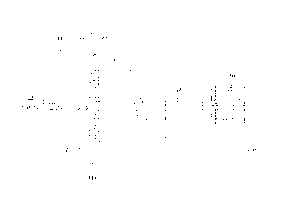
FIG. 1 is a schematic cross-sectional view of a rubbing machine according to
an
embodiment of the present invention, and FIG 2 is a schematic view of a tool
pan according
to an embodiment of the present invention. Referring to FIG 1 and FIG 2, a
rubbing
machine 100 comprises a housing 110, a tool pan assembly 120 and a driving
element 130.
The housing 110 has a feeding inlet 112 and a discharging outlet 114. The tool
pan assembly
120 is disposed inside the housing 110 and comprises two tool pans 122. The
two tool pans
122 are spaced apart by an interval to form a rubbing space 128 that
interconnects with the
feeding inlet 112 and the discharging outlet 114 between the feeding inlet 112
and the
5
CA 02831012 2013-09-23
discharging outlet 114.
Further, each of the tool pans 122 comprises a plurality of homocentric
annular structures
125. Each of the homocentric annular structures 125 has a plurality of rubbing
zones 121,
and at least one ramp 127 is disposed between adjacent rubbing zones 121. Each
of the
ramps 127 extends along a normal direction R of the tool pan 122 corresponding
to the
rampand ramps up gradually towards a fringe of the corresponding tool pan 122.
In this
embodiment, there are, for example, two ramps 127 arranged along the normal
direction R of
the tool pan 122 between every two adjacent rubbing zones 121 of each of the
annular
structures 125.
It shall be noted that, in other embodiments, there may also be more than two
ramps 127
disposed between every two adjacent rubbing zones 121 of each annular
structure 125, and
the number of ramps 127 disposed between every two adjacent rubbing zones 121
is not
limited in the present invention.
Particularly, each of the rubbing zones 121 may also have a chamfer 121a
located at a
front end of the rubbing zone 121. I lere, the terms "front" and "back" are
defined with
respect to a relative rotation direction of the tool pans 122. That is, the
chamfer 121a is
located in the front with respect of the relative rotation direction of the
tool pan 121a.
Furthermore, the rubbing zones 121 of the annular structures 125 in different
annuli may
be spaced apart by different intervals respectively in this embodiment. In
other words, the
ramps 127 of the annular structures 125 in different annuli may have different
widths
respectively. In this embodiment, the ramps 127 nearer to a fringe of the tool
pans 122 have
6
CA 02831012 2013-09-23
smaller widths.
In this embodiment, only one of the two tool pans 122 rotates relative to the
housing II()
while the other remains stationary when the rubbing machine 100 operates.
However, the
present invention is not limited to this; and in other embodiments, both the
tool pans 122 can
rotate relative to the housing 110 but rotate at speeds different from each
other so that a
relative movement takes place therebetween.
In this embodiment, the tool pan 122 that can rotate relative to the housing
110 is
connected with a rotary shaft 132 of the driving element 130 so as to be
rotated by the driving
element 130. Specifically, the driving element 130 is a motor. On the other
hand, the tool
pan 122 that is stationary relative to the housing. 110 may have a material-
guiding hole 123
located substantially at a center of the tool pan 122 and communicating with
the feeding inlet
112. Moreover, the material to be rubbed that is fed from the feeding inlet
112 is transported
into the rubbing zones 128 between the two tool pans 122 by use of a material-
guiding screw
140 in this embodiment. To be more specific, the material-guiding screw 140 is
inserted
through the material-guiding hole 123 of the tool pan 122 and located below
the feeding inlet
112 of the housing 110.
The rubbing machine of the present invention is applicable to the process of
making
paper pulp from plant fibers. To facilitate better understanding of the
present invention by
those skilled in the art, an application of the rubbing machine of the present
invention will be
described with reference to an embodiment thereof.
FIG. 3 is a schematic view illustrating a movement path of a straw between the
two tool
7
CA 02831012 2013-09-23
pans. Referring to FIG 1 through FIG 3, a straw of a herbaceous plant (e.g., a
rice straw or
a wheat straw) is obtained and processed by a pulper machine (not shown) to
remove skins of
the straw through vibration, and are then put into the feeding inlet 112.
Meanwhile, water is
injected through the feeding inlet 112. The straw then falls into spaces
between threads 142
of the material-guiding screw 140 and, accompanying with the flowing water, is
transported
by the rotating material-guiding screw 140 from the material-guiding hole 123
to the rubbing
spaces 128 between the two tool pans 122; and then under the action of a water
flow caused
by the centrifugal force resulting from rotation of the tool pan 122, the
straw is moved
outwards radially to the ramps 127. In this embodiment, the tool pan 122 shown
in FIG 3
rotates in, for example, a clockwise direction, so the straw 200 moves
outwards in a radial
direction relative to the tool pan 122 but also in a slightly leftward
direction.
FIGs. 4A through 41) are schematic views depicting how the rubbing zones
impose
forces on the straws. Referring to FIG 3 and FIG 4A together, the straw 200
moves
upwards along the ramps 127 under the action of the water flow. Because of the
continuous
relative rotation between the two tool pans 122, the rubbing zones 121 of the
two tool pans
121 move in directions indicated by the arrows in FIG. 4A respectively.
Therefore, a force
is applied to the straw 200 by the chamfers 121a located at the front ends of
the rubbing zones
121 so that the straw 200 is pressed to move towards surfaces of the rubbing
zones 121.
Next, as shown in FIG 411, the rotation of the tool pan 122 drives the straw
200 into
between chamfers 121a located at the front ends of the rubbing zones 121
opposite to each
other.
8
= CA 02831012 2013-09-23
Then as shown in FIG 4C, with the continuous rotation of the tool pan 122, the
straw
200 is moved into between the opposite rubbing zones 121 by the chamfers 121a.
At this
point, because a gap between the opposite rubbing zones 121 is smaller than an
original
diameter of the straw 200, a rubbing force is applied to the straw 200.
As shown in FIG. 3 and FIG 41), as the rubbing zones 121 of the two tool pans
122
move away from each other, the straw 200 moves out of the rubbing zones 121
into a next
ramp 127 where the a fiber explosion phenomenon takes place due to an
instantaneous
vacuum effect. Thereby, the so-called separating or fibrillating of fibers can
be achieved.
For example, if an individual straw originally put into the rubbing machine is
a fiber
bundle consisting of multiple fine fibers, the straw can be separated into
multiple fine fibers
through the aforesaid process and this is just the so-called fiber separating.
Moreover, if the
straw originally put into the rubbing machine has already been separated into
individual fine
fibers, then the aforesaid process can have finer fibrils on the skin of the
straw warped up and
this is just the so-called fibrillating.
The fibrillating is favorable for improving the
intertwining force between fibers in the paper pulp to enhance the strength
and toughness of
the resulting paper.
Taking the separating process as an example, the rubbing machine 10 of the
present
invention may also improve the fiber separating rate of each rubbing process
by means of
ramps 127 of different widths. In detail, as shown in FIG. 3, the original
straw 200 floats up
along a bottom surface of the ramp 127 of the innermost circle to a space
between rubbing
zones 121 of the two tool pans 122 where it is separated into fine fibers.
Then, the fibers
9
CA 02831012 2013-09-23
float up along a bottom surface of the ramp 127 of a next circle to a space
between rubbing
zones 121 of the two tool pans 122 where they are separated into finer fibers.
In this way, by
floating up along bottom surfaces of the ramps 127 of the different cycles to
the spaces
between the rubbing zones 121 of the two tool pans 122 repeatedly, the fiber
separating rate of
the straw can reach as high as 95%. Finally, a resulting pulp flows out from
the discharging
outlet 114.
According to the above descriptions, the tool pan assembly of the rubbing
machine of the
present invention has annular structures that are formed into a plurality of
circles, and the
annular structures comprise ramps that allow the material to be rubbed to
float up into the
rubbing zones between the two tool pans effectively so that the material can
be rubbed by the
alternating forces between the two tool pans. As can be known from this, the
rubbing
machine of the present invention is applicable to the paper manufacturing
industry where the
fibers of herbage can be separated effectively by the mechanical force between
the two tool
pans. Thereby, it is unnecessary to use chemicals and this complies with the
modern
conception of environmental protection.
Furthermore, the rubbing machine of the present invention can also be used to
fibrillate
Fine Fibrils resulting from the separating process to improve the strength and
toughness of
paper made from the fibers.
What described above are only preferred embodiments of the present disclosure,
but are
not intended to limit the present disclosure in any form. Although the present
disclosure has
been described above with reference to the preferred embodiments thereof, the
preferred
CA 02831012 2015-02-02
embodiments are not intended to limit the present disclosure. People skilled
in the art can
make slight alterations or modifications as equivalent embodiments on the
basis of the
above disclosures without departing from the scope of the present invention.
However,
any alterations, equivalent changes and modifications made to the above
embodiments,
without departing from the scope of the present disclosure shall all be
covered within the
scope of the present disclosure.
Industrial Applicability
The rubbing machine of the present invention is applicable to the paper
manufacturing industry where the fibers of herbage can be separated or
fibrillated
effectively by the mechanical force between the two tool pans. Thereby, it is
unnecessary
to use chemicals and this complies with the modern conception of environmental
protection.
11