Note: Descriptions are shown in the official language in which they were submitted.
CA 02831199 2013-10-22
WING FOLD SYSTEM WITH LATCH PINS THROUGH
MULTIPLE MATING LUGS
FIELD OF THE DISCLOSURE
This disclosure relates to systems and methods for providing wings,
and more specifically, to systems and methods for latching wings that enhance
aircraft performance.
BACKGROUND OF THE DISCLOSURE
In today's commercial transport industry, it is highly desirable to design
aircraft configurations that yield reduced fuel burn per seat-mile, as fuel
burn per
seat-mile is a metric of fuel efficiency. Efficient aircraft configurations
are ever more
important as fuel costs increase. Aircraft aerodynamic drag and fuel burn are
generally reduced as the aspect ratio of the aircraft wing increases.
Similarly,
operating larger aircraft, carrying more passengers and payload, are generally
more
efficient between two destinations than flying several trips with smaller
aircraft. Thus
larger aircraft and aircraft with longer wingspans tend to be more efficient.
However,
taxiway spacing and gate locations for most airports were established without
providing adequate spacing for aircraft with the longer wingspans that can be
produced with today's technology.
Therefore, a need exists in the art for an aircraft that can benefit from a
long wingspan in flight, while being able to reduce the wingspan while
operating at
an airport.
1
CA 02831199 2016-07-06
SUMMARY
In accordance with one disclosed aspect there is provided a method of
folding a wing of an aircraft. The method involves causing a fold actuator to
move an
unfixed portion of the wing with respect to a fixed portion of the wing
between a flight
position and a folded position. The method also involves causing a latch to
prevent
movement of the unfixed portion of the wing with respect to the fixed portion
of the
wing when the unfixed portion of the wing is in a flight position. The latch
includes a
first lock configured to prevent movement of a latch pin of the latch when the
first lock
is in a first engaged position, the first lock having a first cam. The latch
also includes a
second lock configured to prevent movement of the latch pin when the second
lock is
in a second engaged position, the second lock having a second cam. The first
cam is
configured to contact with the second cam to prevent the second lock from
transitioning to the second engaged position until the first lock is in the
first engaged
position, and the second cam is configured to prevent the first lock from
transitioning
away from the first engaged position until the second lock transitions away
from the
second engaged position. The method further involves transferring a first
force, via a
first shaft of the first lock, from a first piston to the first cam and to a
first lock member;
transferring a second force, via a second shaft of the first lock, from a
first spring to the
first lock member; transferring a third force, via a third shaft of the second
lock, from a
second piston to the second cam and to a second lock member; and transferring
a
fourth force, via a fourth shaft of the second lock, from a second spring to
the second
lock member.
The method may involve biasing, via an actuator spring, at least one of
the first lock and the second lock in the respective first or second engaged
position
when the fold actuator is in an extended position.
Preventing movement of the unfixed portion of the wing may involve
causing the latch pin to engage a group of lugs associated with the latch to
secure the
unfixed portion of wing to the fixed portion of the wing, the group of lugs
including one
or more wingtip lugs each having a first opening, each wingtip lug attached to
the
unfixed portion of the wing, and one or more inner lugs each having a second
opening,
2
CA 02831199 2016-07-06
each inner lug attached to the fixed portion of the wing, the respective first
openings of
the wingtip lugs coinciding with the second opening of the inner lugs for
receiving the
latch pin when the wing is in a flight position.
The method may involve causing a latch actuator to transition the latch
between an open position and a closed position, and sensing, via an unlatched
sensor
when the latch is in the open position, and when the unlatched sensor is
connected to
a latch pin actuator.
The method may involve causing the latch pin to slide substantially
parallel to a longitudinal axis of the aircraft when transitioning between the
open
position and the closed position, and the latch pin may include an inner pin
within an
outer pin, the outer pin including a group of stacked pins, each stacked pin
being
associated with a group of lugs including at least one inner lug and at least
one wingtip
lug and being operable to provide a load path between the group of lugs when
the
latch pin is in the closed position, the inner pin providing a secondary load
path if any
one of the stacked pins is unable to provide the load path for the associated
group of
lugs.
Preventing movement of the latch pin of the latch may involve engaging,
via one of the first lock and the second lock, the outer pin, and engaging,
via the other
of the first lock and the second lock, the inner pin and the outer pin.
The method may involve causing the first spring to bias the first lock
toward the first engaged position, and causing the second spring to bias the
second
lock toward the second engaged position.
The method may involve disengaging, via the first piston connected to the
first cam, the first lock, and transitioning, via the first piston, the first
lock from the first
engaged position to a first disengaged position, disengaging, via the second
piston
connected to the second cam, the second lock, and transitioning, via the
second
piston, the second lock from the second engaged position to a second
disengaged
position.
2A
CA 02831199 2016-07-06
The method may involve preventing, via a first contact member of the first
cam, the first lock from transitioning away from the first engaged position
before the
second lock transitions away from the second engaged position via contact
between
the first contact member of the first cam and a second contact member of the
second
cam when the first lock is in the first engaged position and the second lock
is in the
second engaged position, and preventing, via the second contact member, the
second
lock from transitioning to the second engaged position before the first lock
transitions
to the first engaged position via contact between the second contact member of
the
second cam and the first contact member of the first cam before the first lock
is in first
engaged position.
The method may involve providing a first surface of a first lock member of
the first lock of a group of locks and a third surface of a second lock member
of the
second lock of the group of locks, with respective shapes operable to reduce
contact
with the latch pin in a closed position, providing a second surface of the
first lock
member of the first lock of the group of locks and a fourth surface of the
second lock
member of the second lock of the group of locks, with shapes operable to
reduce
contact with the latch pin while transitioning to an open position. The shape
of the first
surface is operable to reduce movement of the first lock member during
transition to
the first engaged position, and the shape of the third surface is operable to
reduce
movement of the second lock member during transition to the second engaged
position.
The method may involve providing a roller of the first lock member
juxtaposed between the first surface and the second surface, the roller
operable to
reduce a friction force between the first lock member and the latch pin as the
latch pin
moves into a group of lugs.
The method may involve sensing when the first lock is in the first
engaged position via a sensor that senses when the second lock is in the
second
engaged position.
2B
CA 02831199 2016-07-06
The method may involve controlling, via a group of first nubs of the first
lock member, movement of the first lock member to stop the first lock member
in the
first engaged position, creating, via the group of first nubs, a group of
first witness
marks on the latch pin to aid an inspection of the latch, controlling, via a
group of
second nubs of the second lock member, movement of the second lock member to
stop the second lock member in the second engaged position, creating, via the
group
of second nubs, a group of second witness marks on the latch pin to aid the
inspection
of the latch, and identifying, via a quantity of the first nubs differing from
a quantity of
the second nubs, that the group of first nubs create the group of first
witness marks
and the group of second nubs create the group of second witness marks.
In accordance with another disclosed aspect there is provided a wing fold
system of a wing of an aircraft. The system includes a latch configured to
prevent
movement of an unfixed portion of the wing with respect to a fixed portion of
the wing.
The latch includes a latch pin, a first lock including a first cam, and a
second lock
including a second cam. The first cam is configured to contact the second cam
to
prevent the second lock from transitioning to a second engaged position until
the first
lock is in a first engaged position, and the second cam is configured to
prevent the first
lock from transitioning away from the first engaged position until the second
lock
transitions away from the second engaged position. The first cam includes a
first
contact member configured to prevent the first lock from transitioning away
from the
first engaged position before the second lock transitions away from the second
engaged position via contact between the first contact member of the first cam
and a
second contact member comprised by the second cam when the first lock is in
the first
engaged position and the second lock is in the second engaged position. The
second
cam includes the second contact member configured to prevent the second lock
from
transitioning to the second engaged position before the first lock transitions
to the first
engaged position via contact between the second contact member and the first
contact
member before the first lock is in second engaged position. The system further
includes a first shaft of the first lock configured to connect a first lock
member to the
first cam and a first piston, a second shaft of the first lock configured to
connect the
2C
CA 02831199 2016-07-06
first spring with the first lock member, a third shaft of the second lock
configured to
connect a second lock member to the second cam and a second piston, and a
fourth
shaft of the second lock configured to connect the second spring with the
second lock
member.
The system may include a latch actuator configured to transition the latch
between an open position and a closed position, an unlatched sensor to sense
when
the latch is in the open position, the unlatched sensor connected to the latch
actuator,
the latch pin configured to slide substantially parallel to one of a roll
axis, and a
longitudinal axis of the aircraft, and the latch pin including an inner pin
within an outer
pin, the outer pin including a group of stacked pins, each stacked pin being
associated
with a group of lugs including at least one inner lug associated with the
fixed portion of
the wing and at least one wingtip lug associated with the unfixed portion of
the wing
and being operable to provide a load path between the group of lugs when the
latch
pin is in the closed position, the inner pin configured to provide a secondary
load path
when the outer pin is unable to provide a load path.
One of the first lock and the second lock may be configured to engage
the outer pin, and the other of the first lock and the second lock may be
configured to
engage the inner pin and the outer pin.
The first lock may include a first piston configured to disengage the first
lock, and transition the first lock from the first engaged position to a first
disengaged
position, and a first spring configured to bias the first lock to the first
engaged position,
and the second lock may include a second piston configured to disengage the
second
lock, and transition the second lock from the second engaged position to a
second
disengaged position, and a second spring configured to bias the second lock to
the
second engaged position.
In another embodiment there is provided a method of folding a wing of an
aircraft. The method involves moving, via a fold actuator, an unfixed portion
of the wing
with respect to a fixed portion of the wing between a flight position and a
folded
position and preventing, via a latch, movement of the unfixed portion of the
wing with
2D
CA 02831199 2016-07-06
respect to the fixed portion of the wing. The latch includes a first lock
configured to
prevent movement of a latch pin of the latch, and a first cam configured to,
via contact
with a second cam comprising a second lock, prevent the second lock from
transitioning to a second engaged position until the first lock is in a first
engaged
position. The method further involves preventing, via the second cam, the
first lock
from transitioning away from the first engaged position until the second lock
transitions
away from the second engaged position and sliding the latch pin substantially
parallel
to a longitudinal axis of the aircraft when transitioning between an open
position and a
closed position. The latch pin includes an inner pin within an outer pin, the
inner pin
providing a secondary load path if outer pin is unable to provide a load path,
the inner
pin not providing the load path until the outer pin is unable to provide the
load path,
and the outer pin including a group of stacked pins. The method further
involves
engaging, via one of the first lock and the second lock, the outer pin;
engaging, via the
other of the first lock and the second lock, the inner pin and the outer pin;
separating,
via the group of stacked pins, the load path for a group of lugs comprising
one or more
inner lug and one or more wingtip lug; and isolating, via the group of stacked
pins, an
inability of one stacked pin, from remaining stacked pins of the group of
stacked pins,
to provide the load path.
In another embodiment there is provided a wing fold system of a wing of
an aircraft. The system includes a first lock of a latch configured to prevent
movement
of a latch pin of the latch and prevent movement of an unfixed portion of the
wing with
respect to a fixed portion of the wing. The first lock includes a first cam
configured to
prevent a second lock from transitioning to a second engaged position until
the first
lock is in a first engaged position via contact with a second cam of the
second lock.
The system further includes the second lock of the latch. The second lock
includes the
second cam configured to prevent the first lock from transitioning away from
the first
engaged position until the second lock transitions away from the second
engaged
position. The system further includes a latch actuator configured to
transition the latch
between an open position and a closed position and an unlatched sensor to
sense
when the latch is in the open position, the unlatched sensor connected to the
latch
2E
CA 02831199 2016-07-06
actuator. The latch pin is configured to slide substantially parallel to one
of: a roll axis,
and a longitudinal axis of the aircraft. The latch pin includes an inner pin
within an
outer pin, the inner pin configured to provide a secondary load path when the
outer pin
is unable to provide a load path. The outer pin includes a group of stacked
pins. The
group of stacked pins is configured to separate the load path for a group of
lugs
comprising one or more inner lug and one or more wingtip lug. The group of
stacked
pins is configured to isolate an inability of one stacked pin, from remaining
stacked
pins of the group of stacked pins, to carry the load path.
In another embodiment there is provided a method of folding a wing of an
aircraft. The method involves causing a fold actuator to move an unfixed
portion of the
wing with respect to a fixed portion of the wing between a flight position and
a folded
position and preventing, via a latch, movement of the unfixed portion of the
wing with
respect to the fixed portion of the wing when the unfixed portion of the wing
is in a flight
position. The latch includes a first lock configured to prevent movement of a
latch pin
of the latch when the first lock is in a first engaged position, the first
lock having a first
cam, and a second lock configured to prevent movement of the latch pin when
the
second lock is in a second engaged position, the second lock having a second
cam.
The first cam is configured to contact with the second cam to prevent the
second lock
from transitioning to the second engaged position until the first lock is in
the first
engaged position. The second cam is configured to prevent the first lock from
transitioning away from the first engaged position until the second lock
transitions
away from the second engaged position. The method further involves causing the
latch
pin to slide substantially parallel to a longitudinal axis of the aircraft
when transitioning
between the open position and the closed position. The latch pin includes an
inner pin
within an outer pin. The outer pin includes a group of stacked pins, each
stacked pin
being associated with a group of lugs including at least one inner lug and at
least one
wingtip lug and being operable to provide a load path between the group of
lugs when
the latch pin is in the closed position. The inner pin provides a secondary
load path if
any one of the stacked pins is unable to provide the load path for the
associated group
of lugs.
2F
CA 02831199 2016-07-06
In another embodiment there is provided a wing fold system of a wing of
an aircraft. The system includes a latch configured to prevent movement of an
unfixed
portion of the wing with respect to a fixed portion of the wing. The latch
includes a latch
pin, a first lock comprising a first cam, and a second lock comprising a
second cam.
The first cam is configured to contact the second cam to prevent the second
lock from
transitioning to a second engaged position until the first lock is in a first
engaged
position. The second cam is configured to prevent the first lock from
transitioning away
from the first engaged position until the second lock transitions away from
the second
engaged position. The system further includes a latch actuator configured to
transition
the latch between an open position and a closed position and an unlatched
sensor to
sense when the latch is in the open position, the unlatched sensor connected
to the
latch actuator. The latch pin is configured to slide substantially parallel to
one of: a roll
axis, and a longitudinal axis of the aircraft. The latch pin includes an inner
pin within an
outer pin. The outer pin includes a group of stacked pins. Each stacked pin is
associated with a group of lugs including at least one inner lug associated
with the
fixed portion of the wing and at least one wingtip lug associated with the
unfixed
portion of the wing and is operable to provide a load path between the group
of lugs
when the latch pin is in the closed position. The inner pin is configured to
provide a
secondary load path when the outer pin is unable to provide a load path.
BRIEF DESCRIPTION OF THE DRAWINGS
The novel features believed characteristic of the illustrative embodiments
are set forth in the appended claims. The illustrative embodiments, however,
as well
as a preferred mode of use, further objectives and features thereof, will best
be
understood by reference to the following detailed description of an
illustrative
embodiment of the present disclosure when read in conjunction with the
accompanying
drawings, wherein:
2G
CA 02831199 2013-10-22
Figure 1 is a diagram of an aircraft embodying a wing fold controller of
a wing fold system in a flight position in accordance with an illustrative
embodiment;
Figure 2 is a diagram of an aircraft embodying a wing fold controller of
a wing fold system in a folded position in accordance with an illustrative
embodiment;
Figure 3 is a block diagram of a wing of an aircraft with a wing fold
system in accordance with an illustrative embodiment;
Figure 4 is a block diagram of a wing fold system with a group of
latches in accordance with an illustrative embodiment;
Figure 5 is a block diagram of a first lock of a latch of a wing fold
system in accordance with an illustrative embodiment;
Figure 6 is a block diagram of a second lock of a latch of a wing fold
system in accordance with an illustrative embodiment;
Figures 7A and 7B, are a diagram of a wing fold system in a wing
accordance with an illustrative embodiment, Figure 7A is a diagram of a
location of
a wing fold system in a wing, Figure 7B is a perspective top view diagram of
selected elements of a wing fold system with the wing in a flight position in
accordance with an illustrative embodiment;
Figure 8 is a perspective view diagram of wing fold system with a wing
in a folded position in accordance with an illustrative embodiment;
Figure 9 is a perspective view diagram of wing fold system with a wing
in a flight position in accordance with an illustrative embodiment;
Figures 10A and 10B are a top view cutaway diagram of a latch pin
from a latch of a wing fold system in accordance with an illustrative
embodiment,
Figure 10A illustrates the latch pin with the latch in an open position, and
Figure
10B illustrates the latch pin with the latch in a closed position;
3
CA 02831199 2013-10-22
Figures 11A and 11B, are a side view diagram of a wing with a first
latch pin and a second latch pin in accordance with an illustrative
embodiment.
Figure 11A is a side view diagram with a first central axis of the first latch
pin and a
second central axis of the second latch pin each being aligned substantially
parallel
to a centerline of rotation of an unfixed portion of the wing. Figure 11B is a
side
view diagram with each central axis canted away from the centerline of
rotation of
the unfixed portion of the wing.
Figure 12 is a perspective view diagram of selected components of a
latch of a wing fold system of a wing in accordance with an illustrative
embodiment;
Figures 13A ¨ 13D, are a top plan view diagram of a first cam, a first
lock member, a second cam, a second cam member, and a latch pin, of a latch
depicted in accordance with an illustrative embodiment, Figure 13A depicts the
latch
in closed position, with the first lock member and the second lock member
engaged
with latch pin, Figure 13B depicts the second locked member disengaging from
the
latch pin as first lock member remains engage with the latch pin, Figure 13C
depicts
the second locked member further disengaging from the latch pin as first lock
member disengages from the latch pin; and Figure 13D depicts both the first
lock
member and the second lock member fully disengaged from the latch pin before
the
latch pin moves from closed position;
Figure 14, is a perspective view diagram of a locked sensor for a latch
on a wing fold system in accordance with an illustrative embodiment;
Figures 15A ¨ 15C is a diagram of operations for a method of a wing
fold system in accordance with an illustrative embodiment; Figure 15A shows
operations 1502 to 1524 of the method; Figure 15B shows operations 1526 to
1548
of the method; and Figure 15C shows operations 1550 to 1572 of the method.
Figure 16 is an illustration of an aircraft manufacturing and service
method is depicted in accordance with an illustrative embodiment; and
4
CA 02831199 2013-10-22
Figure 17 is an illustration of an aircraft is depicted in which an
illustrative embodiment may be implemented.
DETAILED DESCRIPTION
Unless otherwise noted and where appropriate, similarly named
features and elements of an embodiment of one figure of the disclosure
correspond
to and embody similarly named features and elements of embodiments of the
other
figures of the disclosure. With reference now to the figures, and in
particular, with
reference to Figures 1 and 2, an illustration of a diagram of an aircraft
embodying a
wing fold controller of a wing fold system is depicted in accordance with an
illustrative embodiment. In this illustrative example, aircraft 100 includes
wing 102
and wing 104 attached to body 106; engine 108 attached to wing 102; engine 110
attached to wing 104. Figure 1 depicts wing 102 and wing 104 of aircraft 100
in a
flight position with wingspan 132.Figure 2 depicts wing 102 and wing 104 of
aircraft
100 in a folded position with wingspan 202. Wingspan 202 may be shorter than
wingspan 132.
Wing 102 includes fixed portion 124 and unfixed portion 120. Fixed
portion 124 may be an inboard portion of wing 102, which is fixed to body 106.
Similarly, wing 104 includes fixed portion 126 and unfixed portion 122. Wing
102
includes wing fold system 130 to move unfixed portion 120 with respect to
fixed
portion 124. Wing 104 includes wing fold system 128 to move unfixed portion
122
with respect to fixed portion 126.
Body 106 has tail section 112. Horizontal stabilizer 114, horizontal
stabilizer 116, and vertical stabilizer 118 are attached to tail section 112
of body 106.
Aircraft 100 is an example of an aircraft in which a wing fold system
may be implemented in accordance with an illustrative embodiment. Wing fold
system 128 and wing fold system 130 each may include a latch assembly in
accordance with an illustrative embodiment.
5
CA 02831199 2013-10-22
With reference to Figure 3, Figure 3 is a block diagram of a wing of an
aircraft with a wing fold system in accordance with an illustrative
embodiment. More
specifically, wing 302 may be an illustrative embodiment of wing 102 and/or
wing
104 in Figures 1 and 2. Wing 302 may include flight position 304, folded
position
306, fixed portion 312, unfixed portion 308, and wing fold system 318. The
folding of
wing 302 may allow for an aircraft to be flown with a wingspan that is longer
than
that allowed by an airport, such as but not limited to International Civil
Aviation
Organization "Code E" airports, from which the aircraft may be used, and wing
302
may provide lift for the aircraft.
Flight position 304 may be a state of wing 302. When wing 302 of an
aircraft is in flight position 304, the aircraft may be ready for flight. For
example,
wing 102 and wing 104 of Figure 1 are in a flight position.
Folded position 306 may be a state of wing 302. When wing 302 of an
aircraft is in folded position 306, the aircraft is not ready for flight, but
the overall
wingspan of aircraft 100 may be shorter. A shorter wingspan may allow use of
aircraft 500 in locations at airports that require a shorter overall wingspan.
Fixed portion 312 may be an embodiment of fixed portion 124 of wing
102 and an embodiment of fixed portion 126 of wing 104 of Figures 1 and 2.
Fixed
portion 312 of wing 302 may include wing box 316 and moveable control surfaces
314. Wing box 316 may be a structural component connected to wing 302.
Moveable control surfaces 314 may include flaps that allow for controlling
flight of
aircraft 100.
Unfixed portion 308 may be an embodiment of unfixed portion 120 of
wing 102 and an embodiment of unfixed portion 122 of wing 104 of Figures 1 and
2.
Unfixed portion 308 rotates with respect to fixed portion 312 of wing 302
between
flight position 304 of wing 302 and folded position 306 of wing 302. Unfixed
portion
308 of wing 302 may include wingtip 310. Wingtip 310 may not include moveable
control surfaces 314.
6
CA 02831199 2013-10-22
Wing fold system 318 may be an embodiment of wing fold system 128
and wing fold system 130 of Figures 1 and 2. Wing fold system 318 may move
wingtip 310 between flight position 304 and folded position 306. Wing fold
system
318 may include several features and components as described below.
With reference to Figure 4, Figure 4 is a block diagram of a wing fold
system with a group of latches in accordance with an illustrative embodiment.
More
specifically, wing fold system 402 may include wing 302, fold actuator 404,
and
group of latches 410. Wing fold system 402 may be an embodiment of wing fold
system 318 of aircraft 100 of Figures 1, 2, and 3. Description of Figure 4 may
relate to, and use reference numbers from, Figure 1, Figure 2, and Figure 3.
Wing
fold system 402 may transition wing 302 of an aircraft between flight position
304
and folded position 306 so that the aircraft may have a longer overall
wingspan 132
during flight and a shorter overall wingspan 202 when not in flight.
Fold actuator 404 maybe a single chamber actuator or a dual chamber
actuator and may include actuator lock 406. A single chamber actuator may
reduce
a weight of fold actuator 404. Reducing the weight of fold actuator 404 may
increase a fuel efficiency for aircraft 100 of Figure 1. Fold actuator 404 may
be
connected between unfixed portion 308 of wing 302 and fixed portion 312 of
wing
302 and may provide a force that may move unfixed portion 308 wing 302 with
respect to fixed portion 312 of wing 302. Fold actuator 404 may use hydraulic,
pneumatic, or electrical, or other appropriate power, or any combination
thereof, and
may use linear or rotational motion, or any combination thereof. As depicted
in
Figure 4, fold actuator 404 may be a linear hydraulic actuator.
Actuator lock 406 may include actuator spring 408. Actuator spring
408 may bias actuator lock 406 and may engage fold actuator 404 in an extended
position. Actuator spring 408 may keep actuator lock 406 engaged. Actuator
lock
406 may engage when fold actuator 404 may be in an extended position and,
correspondingly, wing 302 may be in folded position 306. Actuator lock 406 may
disengage when a pressure in a chamber of fold actuator 404 may provide
sufficient
7
CA 02831199 2013-10-22
force that may overcome a spring force from actuator spring 408 and release
actuator lock 406.
Group of latches 410 may include latch 412. Group of latches 410
may secure wingtip 310 of wing 302 in flight position 304. Wing 302 may have a
first
latch in a forward portion of wing 302 and a second latch in an aft portion of
wing
302 as a part of wing fold system 402.
Latch 412 may include group of lugs 422, latch actuator 432, latch pin
434, unlatched sensor 444, and group of locks 446. Latch 412 may secure fixed
portion 312 of wing 302 to unfixed portion 308 of wing 302. Latch 412 may be
in one
of several positions including open position 414 and closed position 416.
Each latch 412 in group of latches 410 may optionally be canted with
respect to an axis that may be parallel to a roll axis, or a longitudinal axis
of an
aircraft connected to wing 302. The roll axis may be a longitudinal axis that
may
extend from a tail to a nose of the aircraft, passing through a center of
gravity of the
aircraft. The roll axis may be substantially perpendicular to a vertical axis,
and
substantially perpendicular to a pitch axis for the aircraft. Each latch 412
in group of
latches 410 may optionally be canted with respect an axis of rotation of
unfixed
portion 308 relative to fixed portion 312 of wing 302 on the aircraft. Canting
each
latch 412 may reduce the size of a fairing that might be required on wing 302
and
may cover latch 412.
In open position 414, latch pin 434 may be fully retracted so that each
wingtip lug 424 of group of lugs 422 may be free to move with respect to each
inner
lug 428 of group of lugs 422. Unfixed portion 308 of wing 302 may connect to
wingtip lug 424 and may transition between folded position 306 and flight
position
304. In open position 414, each lock of group of locks 446 may be in a
disengaged
position.
In closed position 416, latch pin 434 may be fully extended through
group of lugs 422 and may prevent group of lugs 422 from moving with respect
to
8
CA 02831199 2013-10-22
each other, which thereby may prevent unfixed portion 308 of wing 302 from
moving
with respect to fixed portion 312 of wing 302. In closed position 416, each
lock of
group of locks 446 may be in an engaged position.
When transitioning between open position 414 and closed position
416, latch pin 434 may be partially extended through a portion of group of
lugs 422.
When transitioning between open position 414 and closed position 416, each
lock of
group of locks 446 may transition between an engaged position and a disengaged
position.
Group of lugs 422 may include one or more wingtip lug 424 and one or
more inner lug 428. Each lug of group of lugs 422 may include an opening
through
which latch pin 434 may move. Group of lugs 422 may secure unfixed portion 308
of wing 302 to fixed portion 312 of wing 302. Group of lugs of 422 may be
interlaced
when wing 302 may be in flight position 304.
Wingtip lug 424 may include opening 426 that may coincide with
opening 430 of inner lug 428 and may facilitate entry of latch pin 434 within
wingtip
lug 424 and inner lug 428. Wingtip lug 424 may be attached to and may extend
from
wingtip 310 of unfixed portion 308 of wing 302.
Inner lug 428 may be attached to and may extend from fixed portion
312 of wing 302. Inner lug 428 may include opening 430 that may coincide with
opening 426 of wingtip lug 424 and may facilitate entry of latch pin 234
within wingtip
lug 424 and inner lug 428.
Latch actuator 432 may transition latch 412 between open position 414
and closed position 416 by moving latch pin 434. Latch actuator 432 may be a
linear hydraulic actuator. Latch actuator 432 may use hydraulic, pneumatic, or
electrical, or other appropriate power, or any combination thereof, and may
use
linear or rotational motion, or any combination thereof.
Latch pin 434 may be constructed as a pin with a pin, which may
include inner pin 438 and outer pin 440.
9
CA 02831199 2013-10-22
Latch pin 434 may interlock group of lugs 422 and may prevent unfixed
portion 308 of wing 302 from moving with respect to fixed portion 312 of wing
302.
Latch pin 434 may slide substantially parallel to a roll axis, an outermost
rib of fixed
portion 312 of wing 302, an axis of rotation of unfixed portion 308 relative
to fixed
portion 312 of wing 302 on the aircraft or a longitudinal axis, of an aircraft
connected
to wing 302. Each latch pin 434 may also be aligned canted relative to an axis
as
described immediately above.
Outer pin 440 may surround inner pin 438. Outer pin 440 may provide
a load path between wingtip lug 424 and inner lug 428. Outer pin 440 may
optionally include group of stacked pins 442. Outer pin 440 may be configured
such
that a first part of inner pin 438 may not provide the load path while a
second part of
outer pin 440, which may encircle first part of inner pin 438 may be providing
the
load path.
Inner pin 438 may provide a secondary pin to provide a secondary load
path if outer pin 440 may be unable to provide the load path. Inner pin 438
may be
not loaded until outer pin 440 may be unable to provide the load path. Inner
pin 438
may be configured such that a gap may exist between outer pin 440 and inner
pin
438. Inner pin 438 may be configured such that inner pin 438 does not directly
contact outer pin 440.
Group of stacked pins 442 may separate load paths for groups of lugs
422. A first load path may include one or more first inner lugs, one or more
first
wingtip lug 424 and a first stacked pin of group of stacked pins 442. The
first load
path may be separate from a second load path that may include one or more
second
inner lug 428, one or more second wingtip lug 424 from group of lugs 422, and
a
second stacked pin of group of stacked pins 442. An inability of the first
stacked pin
to provide the first load path may be independent from an inability of the
second
stacked pin to provide the second load path.
CA 02831199 2013-10-22
Unlatched sensor 444 may sense when latch 412 may be in open
position. Unlatched sensor 444 may be connected to latch actuator 432 and may
sense based on contact with latch pin 434.
Group of locks 446 may prevent movement of latch pin 434 when latch
412 may be in closed position 416. First lock 502 of Figure 5 of group of
locks 446
may connect to second lock 602 of Figure 6 of group of locks 446 so that
operation
of first lock 502 may be interdependent on operation of second lock 602.
With reference to Figure 5, Figure 5 is a block diagram of a first lock
of a latch of a wing fold system in accordance with an illustrative
embodiment. More
specifically an illustration of a block diagram of first lock 502 of latch 412
of wing fold
system 402 is depicted in accordance with an illustrative embodiment.
Description of Figure 5 may relate to, and use reference numbers
from, Figure 1, Figure 2, Figure 3, and Figure 4. First lock 502 may be an
embodiment of first lock 502 of group of locks 446 of latch 412 of group of
latches
410 of wing fold system 402 and wing fold system 318 of aircraft 100 of Figure
1,
Figure 2, Figure 3, and Figure 4.
First lock 502 may include: first spring 508, first piston 510, first cam
512, first lock member 516, and first group of shafts 528. First lock 502 may
engage
latch pin 434 after latch pin 434 may be inserted into group of lugs 422.
First lock
502 may transition between first engaged position 504 and first disengaged
position
506.
First engaged position 504 may prevent latch pin 434 from transitioning
away from closed position 416. When in first engaged position 504, a portion
of first
lock member 516 may contact a portion of latch pin 434 and may prevent latch
pin
434 from moving.
First disengaged position 506 may allow latch 412 to transition
between open position 414 and closed position 416. When in a fully disengaged
position, first lock member 516 may not contact a portion of latch pin 434 and
may
11
CA 02831199 2013-10-22
not prevent latch pin 434 from moving. First lock member 516 may, when in a
partially disengaged position, contact a portion of latch pin 434 but may not
prevent
latch pin 434 from moving.
First spring 508 may engage first lock member 516 and may bias first
lock 502 to first engaged position 504. First spring 508 may be connected to
second
shaft 532 of first group of shafts 528.
First piston 510 may disengage first lock 502 and may transition first
lock 502 to first disengaged position 506 by moving first lock member 516.
First
piston 510 may provide a sufficient force to overcome a first spring force of
first
spring 508. First piston 510 may be connected to first cam 512 and may
transfer
movement and force from first piston 510 to first lock member 516.
First cam 512 may include first contact member 514. First cam 512
may be shaped to inhibit second lock 602 from transitioning to second engaged
position 604 until first lock 502 may be in first engaged position 504. First
cam 512
may be shaped to inhibit first lock 502 from transitioning from first
disengaged
position 506 until second lock 602 has transitioned away from a second
disengaged
position.
First contact member 514 may be shaped so that when first lock 502
may be in first engaged position 504 and second lock 602 may be in second
engaged position 604, contact between first contact member 514 of first cam
512
and second contact member 614 of second cam 612 may prevent first cam 512 and
first lock 502 from transitioning away from first engaged position 504 before
second
lock 602 may transition away from second engaged position 604. First contact
member 514 may be shaped so that when first lock 502 may be in first
disengaged
position 506, contact between first contact member 514 of first cam 512 and
second
contact member 614 of second cam 612 may prevent second cam 612 and second
lock 602 from transitioning away from a second disengaged position before
first lock
502 may transition away from first disengaged position 506. First contact
member
12
CA 02831199 2013-10-22
514 may prevent second lock member 616 of second lock 602 from contacting
latch
pin 434 while latch pin 434 may be transitioning from open position 414 to
closed
position 416.
First lock member 516 may include: first surface 518, second surface
520, group of first connection points 522, roller 524, and group of first nubs
526.
First lock member 516 may contact latch pin 434 and may prevent latch pin 434
from
moving after latch pin 434 may be in closed position 416 to bring first lock
502 to first
engaged position 504.
First surface 518 may minimize, via its shape, contact with latch pin
434. First surface 518 may minimize, via its shape, any combination of
movement
and rotation of first lock member 516 during transition to first disengaged
position
506. First surface 518 may be shaped cylindrically with a curvature
substantially
similar a curvature of latch pin 434. First surface 518 may be angularly
offset with
respect to second surface 520.
Second surface 520 may minimize, via its shape, contact with latch pin
434 when first lock 502 may be in first disengaged position 506 and when latch
412
may transition from open position 414 to closed position 416. Second surface
520
may be shaped cylindrically with a curvature substantially similar to a
curvature of
latch pin 434. Second surface 520 may be angularly offset with respect to
first
surface 518.
Group of first connection points 522 may be connections between first
lock member 516 and one or more shafts of first group of shafts 528. Each
first
connection point of group of first connection points 522 may be scalloped at
first
connections located between first lock member 516 and each shaft of first
group of
shafts 528. The scalloping at group of first connection points 522 may remove
a
torsional connection between first piston 510 and first lock member 516 when
first
lock member 516 and first shaft 530 of group of shafts 528 may be sheared by
latch
pin 434.
13
CA 02831199 2013-10-22
Roller 524 may reduce friction between first surface 518 of first lock
member 516 and latch pin 434 as latch pin may 434 move into groups of lugs 422
that may be interlaced, and latch 412 may transition from open position 414 to
closed position 416 and while first spring 508 may bias first lock 502 towards
first
engaged position 504. Roller 524 may be on a single lock member of a single
lock
of group of locks 446 due to an interdependent nature of group of locks 446
where
first cam 512 with second cam 612 of second lock 602 may prevent second lock
602
member from contacting latch pin 434 while latch 412 may be in transition
between
open position 414 and closed position 416.
Group of first nubs 526 may extend from first lock member. Group of
first nubs 526 may prevent first lock member 516 from moving too far in first
engaged position 504. Group of first nubs 526 may create a group of first
witness
marks on latch pin 434 to aid inspection of latch pin 434. A quantity of nubs
in group
of first nubs 526 on first lock member 516 of first lock 502 may differ from a
quantity
of second nubs on a second lock and may identify that group of first nubs 526
may
create a group of first witness marks. Group of first nubs 526 may be one nub.
First group of shafts 528 may include first shaft 530 and second shaft
532. First group of shafts 528 may connect various elements of first lock 502
and
may transfer force and torque between the various elements of first lock 502.
Second shaft 532 may connect first spring 508 with first lock member
516. Second shaft 532 may transfer torque from first spring 508 to first lock
member
516 and may transition first lock 502 to first engaged position 504 after
latch 412
may be fully extended into closed position 416 between group of lugs 422,
which
may include an interlaced wingtip lug 424 and inner lug 428.
Second shaft 532 may include first slot 534 that when viewed, may
indicate position of first lock member 516 as being in one of, or in between,
first
engaged position 504 and first disengaged position 506.
14
CA 02831199 2013-10-22
First shaft 530 may connect first lock member 516, first cam 512, and
first piston 510. First shaft 530 may transfer resistance from first cam 512
to first
lock member 516 and may prevent movement of first lock member 516 based on
position of first cam 512 with respect to second cam 612 of second lock 602.
With reference to Figure 6, Figure 6 is a block diagram of a second
lock of a latch of a wing fold system in accordance with an illustrative
embodiment.
More specifically, an illustration of a block diagram of second lock 602 of
latch 412 of
wing fold system 402 is depicted in accordance with an illustrative
embodiment.
Description of Figure 6 may relate to, and use reference numbers from, Figure
1,
Figure 2, Figure 3, Figure 4, and Figure 5.
Second lock 602 may include: second spring 608, second piston 610,
second cam 612, second lock member 616, and second group of shafts 628, and
locked sensor 636. Second lock 602 may be an embodiment of second lock 602 of
group of locks 446 of latch 412 of group of latches 410 of wing fold system
402 and
wing fold system 318 of aircraft 100 of Figures 1, 2, 3, and 4. Second lock
602 may
engage latch pin 434 after latch pin 434 is inserted into group of lugs 422.
Second
lock 602 may transition between second engaged position 604 and second
disengaged position 606.
Second engaged position 604 may prevent latch pin 434 from
transitioning away from closed position 416. When in second engaged position
604,
a portion of first lock member 516 may contact a portion of latch pin 434 and
may
prevent latch pin 434 from moving. When in second engaged position 604, second
cam 612 may prevent first cam 512 from moving, which may prevent first lock
member 516 from moving.
Second disengaged position 606 may allow latch 412 to transition
between open position 414 and closed position 416. When in a fully disengaged
position, second lock member 616 may not contact a portion of latch pin 434
and
may not prevent latch pin 434 from moving. When in a partially disengaged
position,
CA 02831199 2013-10-22
second lock member 616 may contact a portion of latch pin 434 but may not
prevent
latch pin 434 from moving.
Second spring 608 may engage second lock 602 and may bias second
lock 602 to second engaged position 604. Second spring 608 may connect to
fourth
shaft 632 of second group of shafts 628.
Second piston 610 may disengage second lock 602 and may transition
second lock 602 to disengaged position 606 by moving second lock member 616.
Second piston 610 may provide a sufficient force to overcome a second spring
force
of second spring 608. Second piston 610 may connect to second cam 612 and may
transfer movement and force from second piston 610 to second lock member 616.
Second cam 612 may include second contact member 614. Second
cam 612 may be shaped to inhibit second lock 602 from transitioning to second
engaged position 604 until first lock 502 may be in first engaged position
504.
Second cam 612 may be shaped to inhibit first lock 502 from transitioning from
first
disengaged position 506 until second lock 602 may have transitioned away from
second disengaged position 606.
Second contact member 614 may be shaped so that when first lock
502 may be in first engaged position 504 and second lock 602 may be in second
engaged position 604, contact between first contact member 514 of first cam
512
and second contact member 614 of second cam 612 may prevent first cam 512 and
first lock 502 from transitioning away from first engaged position 504 before
second
lock 602 may transition away from second engaged position 604. Second contact
member 614 may be shaped so that when first lock 502 may be in first
disengaged
position 506, contact between first contact member 514 of first cam 512 and
second
contact member 614 of second cam 612 may prevent second cam 612 and second
lock 602 from transitioning away from second disengaged position 606 before
first
lock 502 may transition away from first disengaged position 506. Second
contact
member 614 may prevent second lock member 616 of second lock 602 from
16
CA 02831199 2013-10-22
contacting latch pin 434 while latch pin 434 may be transitioning from open
position
414 to closed position 416.
Second lock member 616 may include: third surface 618, fourth
surface 620, group of second connection points 622, and group of second nubs
626.
Second lock member 616 may contact latch pin 434 and may prevent latch pin 434
from moving after latch pin 434 may be in closed position 416 and first lock
502 may
be in first engaged position 504 to bring second lock 602 to second engaged
position 604.
Third surface 618 may minimize, via its shape, contact with latch pin
434. Third surface 618 may minimize, via shape, any combination of movement
and
rotation of second lock member 616 during transition to second disengaged
position
606. Third surface 618 may be shaped cylindrically with curvature
substantially
similar to latch pin 434 curvature of latch pin 434. Third surface 618 may be
angularly offset with respect to fourth surface 620.
Fourth surface 620 may minimize, via its shape, contact with latch pin
434 when second lock 602 may be in second disengaged position 606 and when
latch 412 may transition from open position 414 to closed position 416. Fourth
surface 620 may be shaped cylindrically with curvature substantially similar
to latch
pin 434 curvature of latch pin 434. Fourth surface 620 may be angularly offset
with
respect to third surface 618.
Group of second connection points 622 are connections between
second lock member 616 and one or more shafts of second group of shafts 628.
Each second connection point of group of second connection points 622 may be
scalloped at second connections located between second lock member 616 and
each shaft of second group of shafts 628. The scalloping at second connection
points 622 may remove torsional connection between second lock member 616 and
locked sensor 636 when second lock member 616 and third shaft 630 of group of
shafts 628 may be sheared by latch pin 434.
17
CA 02831199 2013-10-22
Group of second nubs 626 may prevent second lock member 616 from
moving too far in second engaged position 604. Group of second nubs 626 may
create a group of second witness marks on latch pin 434 to aid inspection of
latch
pin 434. A quantity of second nubs of second lock 602 may differ from a
quantity of
first nubs of first lock 502 and may identify that group of second nubs may
create
group of second witness marks.
Second group of shafts 628 may include third shaft 630 and fourth
shaft 632. Second group of shafts 628 may connect various elements of second
lock 602 and may transfer force and torque between the various elements of
second
lock 602.
Fourth shaft 632 may connect second spring 608 with second lock
member 616. Fourth shaft 632 may transfer torque from second spring 608 to
second lock member 616 and may transition second lock 602 to second engaged
position 604 after latch 412 may be fully extended into closed position 416
between
group of lugs 422, which may include a wingtip lug 424 interlaced with an
inner lug
428. Fourth shaft 632 may include second slot 634 that when viewed, may
indicate
position of second lock 602 as being in one of or in between second engaged
position 604 and second disengaged position 606.
Third shaft 630 may connect second lock member 616, second cam
612, and second piston 610. Third shaft 630 may transfer resistance from
second
cam 612 to second lock member 616 and may prevent movement of second lock
member 616 based on position of second cam 612 with respect to first cam 512
of
first lock 502.
Locked sensor 636 may sense when second lock 602 may be in
second engaged position 604. Second lock 602 being in second engaged position
604 may require first lock 502 to be in first engaged position 504 and latch
pin 434 to
be in between group of lugs 422 such that latch 412 may be in closed position
416.
Locked sensor 636 may include a redundant set of sensors. Locked sensor 636
18
CA 02831199 2013-10-22
may be any one of: an ultrasonic sensor, and electrical sensor, a mechanical
contact sensor, other sensor systems as may be appropriate, or any combination
thereof.
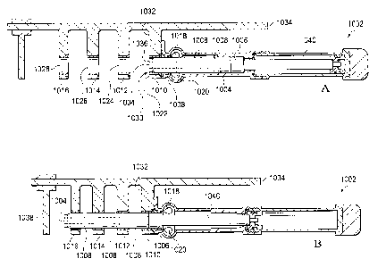
With reference to Figure 7, Figure 7, is a diagram of a wing fold
system in a wing accordance with an illustrative embodiment, Figure 7A is a
diagram of a location of a wing fold system in a wing, Figure 7B is a
perspective top
view diagram of selected elements of a wing fold system with the wing in a
flight
position in accordance with an illustrative embodiment. More specifically,
Figure 7A
depicts a location for wing fold system 702 on aircraft 700, in accordance
with an
illustrative embodiment. The illustration presents an area of a left wingtip
of aircraft
700, such as shown for unfixed portion 122 of aircraft 100 in Figure 1. An
inverse
arrangement may be applicable for a right wingtip of an aircraft such as shown
for
unfixed portion 120 of aircraft 100 in Figure 1.
With reference to Figure 7B, wing fold system 702 may include: fold
actuator 704, centerline of rotation 706, second latch 708, second latch
actuator
710, unfixed portion 712, fixed portion 714. Second latch 708 may be an
example of
an embodiment of latch 412 as shown in Figure 4. A first latch may be located
at a
forward edge of the wing fold system, but is not visible in this view. Unfixed
portion
712 may be rotatably connected to fixed portion 714 about centerline of
rotation 706
of unfixed portion 712.
With reference to Figure 8, Figure 8 is a perspective view diagram of
wing fold system with a wing in a folded position in accordance with an
illustrative
embodiment. More specifically, the side perspective viewpoint looks up and in
toward fixed portion 816 of wing fold system 802 in folded position 306. Wing
fold
system 802 is shown with unfixed portion 804 of wing 302 raised in folded
position
306.
Wing fold system 802 may include: unfixed portion 804, first latch 806,
second latch 808, fold actuator 810, wingtip lug 812 of group of lugs 422,
inner lug
19
CA 02831199 2013-10-22
814 of group of lugs 422, and fixed portion 816, a first latch pin 818, and a
second
latch pin 820.
First latch 806 and second latch 808 may each be examples of latch
412 in group of latches 410 as shown in Figure 4. Unfixed portion 804 may be
in
folded position 306 due to extension of fold actuator 810 while first latch
pin 818
within first latch 806 and second latch pin 820 within second latch 808 may
each be
retracted to open position 414, by first latch actuator 822 and second latch
actuator
824 respectively. First latch actuator 822 and second latch actuator 824 may
each
be an example of latch actuator 432 in Figure 4. In open position 414, each
latch
actuator may retract its respective latch pin from engagement with group of
lugs 422,
such as wingtip lug 812 on unfixed portion 804 and inner lug 814 on fixed
portion
816.
With reference to Figure 9, Figure 9 is a perspective view diagram of
wing fold system with a wing in a flight position in accordance with an
illustrative
embodiment. More specifically, Figure 9 presents a view looking up and in
toward
wing fold system 902 with unfixed portion 904 of wing 302 lowered in flight
position
304. First latch 906 and second latch 908 may each be in closed position 416.
First
latch 906 and second latch 908 may each be examples of latch 412 in group of
latches 410 as shown in Figure 4. Retraction of an extension member of fold
actuator 910 may have moved unfixed portion 904 to flight position 304. First
latch
pin 918 within first latch 906 and second latch pin 920 within second latch
908 may
have been extended to closed position 416 by their respective latch actuator
432. In
closed position 416, each latch actuator 432 may extend its latch pin 434 from
engagement with group of lugs 422, such as wingtip lug 912 on unfixed portion
904
and inner lug 914 on fixed portion 916.
With reference to Figure 10, Figure 10 is a top view cutaway diagram
of a latch pin from a latch of a wing fold system in accordance with an
illustrative
embodiment. Figure 10A illustrates the latch pin with the latch in an open
position,
and Figure 10B illustrates the latch pin with the latch in a closed position.
CA 02831199 2013-10-22
With reference to Figure 10A, Figure 10A illustrates the latch pin with
the latch in an open position. More specifically, Figure 10A, depicts latch
pin 1002
in open position 414. In Figure 10A, latch pin 1002 is shown of with an inner
pin
1004, and an outer pin 1006. Outer pin 1006 may be a solid pin, or as shown in
Figure 10, outer pin 1006 may be group of stacked pins 1008. A first latch pin
may
be located at a front spar of wing 302. A second latch pin may be located at a
rear
spar of wing 302.
Group of lugs 422 for fixed portion 1034 may include a quantity
greater than one inner lug 428 as shown in Figure 4. Illustrative embodiments
may
provide for group of lugs 422 for fixed portion 1034, that may include a
quantity of
four inner lug 428 as shown in Figure 10 as inner lug 1010, inner lug 1012,
inner lug
1014, and inner lug 1016. For clarity of viewing of group of stacked pins
1008,
group of lugs 422 for unfixed portion 308, which may interleave with group of
lugs
422 from fixed portion 1034, are not shown in Figure 10.
Group of lugs 422 for unfixed portion 308 may include a quantity
greater than one wingtip lug 424. A quantity of three wingtip lug 424. Latch
pin
1002 being configured including outer pin 1006, inner pin 1004, the quantity
of four
inner lug 428, and the quantity of three wingtip lug 424 may provide a
redundancy
for providing a load path between unfixed portion 308 and fixed portion 312
that may
be equal or greater than current systems and methods, such as but not limited
to
those that may use eight latch pins that may slide through three or more lugs.
First
lock 1018, and second lock 1020 may provide redundancy to ensure that latch
pin
1002 in closed position 416, as shown in Figure 4, will remain in closed
position 416
until commanded to open position 414.
Group of stacked pins 1008 may be configured such that group of
stacked pins 1008 may not be directly in contact with inner pin 1004. An inner
diameter of outer pin 1006 may be greater than an outer diameter of inner pin
1004.
A space may separate inner pin 1004 from outer pin 1006 such that a load on
outer
21
CA 02831199 2013-10-22
pin is not applied to inner pin while the space between inner pin 1004 and
outer pin
1006 exists.
Inner pin 1004 may have a retention nut 1036 connected at an end of
inner pin 1004. Retention nut 1036 may provide a barrier that may assist
retraction
of group of stacked pins 1008 when inner pin 1004 is retracted. Retention bolt
1038
may extend from fixed portion 1034 across an extended diameter of opening
1028.
If any part of inner pin 1004 were to become disconnected from latch actuator
1040,
retention bolt 1038 may retain the part from exiting latch pin 1002 beyond
retention
bolt 1038.
Outer pin 1006 being over inner pin 1004 may provide a secondary
strength for latch pin 1002. If one of inner pin 1004 or outer pin 1006 were
unable to
provide a load path, the other may be configured as strong enough to provide
the
load path. Redundant ability to carry the load path may keep group of lugs 422
in an
interlaced engagement that may hold wing 302 in flight position 304. Outer pin
1006
including stacked pins 1008, instead of being a single element outer pin 1006,
may
add a further layer of redundancy to latch 412. If any one of the stacked pins
1008
were to unable to provide the load path, the other stacked pins may still be
intact,
and may provide load bearing capacity for outer pin 1006 for each of the
undamaged
stacks. Similarly, any abnormal load on any individual lug in group of lugs
422 may
remain isolated at that lug by the stacked pin associated with the individual
lug.
Providing layers of redundancy in each latch pin 434, may allow wing
fold system 402 to hold unfixed portion 308 in flight position 304 without
requiring
space within, or adding weight to wing 302 that may be required by an
additional
latch system to provide redundancy. Less space and weight required allow wing
302 to be narrower and lighter, which may increase wing 302 performance and
aircraft fuel efficiency. Inner pin 1004 being configured to only provide the
load path
when outer pin 1006 is unable to provide the load path may allow inner pin
1004 to
be configured of a size, material, and strength to provide the load path until
inspection and/or repair of outer pin 1006 is available. Size and strength of
inner pin
22
CA 02831199 2013-10-22
1004 may be less than that required for single pin latches in current wing
fold
designs.
In open position 414 latch pin 1002 may be retracted from engagement
with group of lugs 422 connected to fixed portion 1034 of wing 302, which may
include inner lug 1010, inner lug 1012, inner lug 1014, and inner lug 1016.
Inner lug
1010, inner lug 1012, inner lug 1014, and inner lug 1016 may each be an
example of
an embodiment of inner lug 428 shown in Figure 4. Inner lug 1010, inner lug
1012,
inner lug 1014, and inner lug 1016 may each include a respective opening 1022,
opening 1024, opening 1026, and opening 1028.
In open position 414, end 1030 of latch pin 1002 may be retracted to fill
opening 1022, but may not extend beyond edge 1032 of inner lug 1010. In open
position 414, latch pin 1002 may be retracted from group of lugs 422
sufficiently to
allow wingtip lug 424 to pass into spaces between inner lug 1010, inner lug
1012,
inner lug 1014, and inner lug 1016, and unfixed portion 308 of wing 302
connected
to wingtip lug 424 may transition between folded position 306 and flight
position 304.
In open position 414, as shown in figure 10A, first lock 1018 may be in
first disengaged position 606. In open position 414, as shown in Figure 10A,
second lock 1020 may be in second disengaged position 606.
With reference to Figure 10B, Figure 10B illustrates the latch pin with
the latch in a closed position. More specifically, latch pin 1002 is shown in
closed
position 416. In closed position 416 latch pin 1002 may be retracted from
engagement with group of lugs 422 connected to fixed portion 312 of wing 302,
which may include inner lug 1010, inner lug 1012, inner lug 1014, and inner
lug
1016. Inner lug 1010, inner lug 1012, inner lug 1014, and inner lug 1016 may
each
be an example of an embodiment of inner lug 428 shown in Figure 4. In closed
position 416, latch pin 1002 may be engaged with group of lugs 422
sufficiently to
also engage with any wingtip lug 424 in spaces between inner lug 1010, inner
lug
23
CA 02831199 2013-10-22
1012, inner lug 1014, and inner lug 1016, such that unfixed portion 308 of
wing 302
connected to wingtip lug 424 may not move from flight position 304.
With reference to Figure 11, a side view diagram of a wing with a first
latch pin and a second latch pin is depicted in accordance with an
illustrative
embodiment. Figure 11A is a side view diagram with a first central axis of the
first
latch pin and a second central axis of the second latch pin each being aligned
substantially parallel to a centerline of rotation of an unfixed portion of
the wing.
Figure 11B is a side view diagram with each central axis canted away from the
centerline of rotation of the unfixed portion of the wing.
With reference to Figure 11A, Figure 11A is a side view diagram with
a first central axis of the first latch pin and a second central axis of the
second latch
pin each being aligned substantially parallel to a centerline of rotation of
an unfixed
portion of the wing. Figure 11B is a side view diagram with each central axis
canted
away from the centerline of rotation of the unfixed portion of the wing. More
specifically, wing 1102 includes: fold actuator 1104, centerline of rotation
1106 of
unfixed portion 308 of wing 1102, first latch pin 1108 with a first central
axis 1110,
second latch pin 1112 with a second central axis 1114. Centerline of rotation
1106
in Figure 11 may be an example of an embodiment of centerline of rotation 706
in
Figure 7.
Orienting each latch pin in a generally horizontal alignment instead of
in a generally vertical alignment may allow for thinner wing construction.
Orienting
each latch pin in a horizontal alignment instead of in a vertical alignment
may
enhance inspection of each latch pin condition or status, and may enhance
repair,
replacement, or manual activation or locking during maintenance on each latch
pin.
Similarly, a central axis of each latch pin may be essentially parallel to a
length of a
rib of wing 1102, or to an axis of rotation for unfixed portion 904.
With reference to Figure 11B, Figure 11B is a side view diagram with
each central axis canted away from the centerline of rotation of the unfixed
portion of
24
CA 02831199 2013-10-22
the wing. More specifically, Figure 11B depicts central axis 1110 of first
latch pin
1108 and central axis 1114 of second latch pin 1112 each canted downward, in a
direction of an extension of the respective latch pin and away from centerline
of
rotation 1106.
By canting central axis 1110 and/or central axis 1114, first latch pin
1108 and/or second latch pin 1112 may be inserted inside wing 1102 without
requiring expanding a width of, or changing a shape of wing 1102 to
accommodate
the first latch pin 1108 and/or the second latch pin 1112. Without canting
central
axis 1110 and/or central axis 1114, as shown in Figure 11A, the dimensions of
each
latch may exceed extend outside a desired shape and dimension of wing 1102.
Canting central axis 1110 and/or central axis 1114 may allow keeping the
desired
shape and dimensions of wing 1102 and may allow wing 1102 to be narrower
and/or
lighter than if central axis 1110 and/or central axis 1114 are substantially
parallel to
centerline of rotation 1106 for unfixed portion 308 of wing 1102. Because a
trailing
edge of wing 1102 may be narrower than a leading edge of wing 1102, it may be
that only the second latch pin, located closer to the trailing edge of wing
302, may be
canted. A narrower and/or lighter wing 1102 may increase wing 1102 performance
and efficiency and may increase aircraft 100 fuel efficiency.
Any canted latch pin may still pass through and engage group of lugs
422 in a manner similar to those depicted in Figure 10A and Figure 10B, with
the
exception that opening 1022, opening 1024, opening 1026 and opening 1028,
which
may be formed within respective inner lug 1010, inner lug 1012, inner lug
1014, and
inner lug 1016, may each be formed at an angle that may be different than
those
depicted Figure 10A and Figure 10B, where the openings are identically shaped
with a centerline that may be one of substantially horizontal, and
substantially
parallel to centerline of rotation 706. A centerline of each opening may align
instead
with an angle that may be substantially parallel to a cant angle of their
respective
latch pin. With a central axis of a latch canted, a shape of each opening may
be
CA 02831199 2013-10-22
different than a shape of each other opening to allow for an extension of a
respective
latch pin to extend and pass through each opening unimpeded.
With reference now to Figure 12, a perspective view diagram of
selected components of a latch of a wing fold system of a wing is depicted in
accordance with an illustrative embodiment. More specifically, a perspective
view of
selected interior components of latch 1202 of wing fold system 402 is depicted
from
above in accordance with an illustrative embodiment. Latch 1202 may be an
example of an embodiment of latch 412 of Figure 4 such as second latch 708 of
Figure 7.
Latch 1202 may include: first lock 1204, second lock 1206, inner pin
1238, and outer pin 1240. First lock 1204 may include: first spring 1208,
first piston
1210, first cam 1212, group of first connection points 1214, first lock member
1216,
first shaft 1218, second shaft 1242, first slot 1244, and first knob 1246.
Group of first connection points 1214 may provide redundant features
for latch 1202. Redundant features provided may include managed and sequenced
shearing of first shaft 1218 and second shaft 1242 from first lock member
1216.
First connection points 1214 may provide a stronger connection between first
lock
member 1216 and second shaft 1242 than first connection points 1214 provide
between first lock member 1216 and first shaft 1218. Therefore, a shear force
imparted to first lock member 1216 may result in a shear separation between
first
lock member 1216 and first shaft 1218 before a shear separation occurs between
first lock member 1216 and second shaft 1242.
Thus, if first lock member 1216 shears apart from first shaft 1218,
operation of first cam 1212 and second cam 1224 may be unaffected.
Nonetheless,
if first lock member 1216 shears apart from first shaft 1218, then a position
of first
lock member 1216 may be independent of and unaffected by movements of first
cam 1212 and second cam 1224.
26
CA 02831199 2013-10-22
If latch pin 1234 is in closed position 416 when first lock member 1216
shears from first shaft 1218, then first spring 1208 may apply a force that
may act on
first lock member 1216 and may hold first lock member 1216 in first engaged
position 504 against latch pin 1234. Despite a position of or an indication of
a
position of first cam 1212, a visual inspection of first slot 1244 in second
shaft 1242
may indicate that first lock member 1216 may be in first engaged position 504
against latch pin 1234.
Accordingly, if latch pin 1234 is in open position 414 when first lock
member 1216 shears from first shaft 1218, then, despite a position of or an
indication of a position of first cam 1212, a visual inspection of first slot
1244 in
second shaft 1242 may indicate an actual position for first lock member 1216,
such
as being in first disengaged position 506.
Additionally, if first lock member 1216 shears from first shaft 1218
when latch pin 1234 is in closed position 416, then any movement of first cam
1212
may be unable to move first lock member 1216 from first engaged position 504
to
first disengaged position 506. If first lock member 1216 shears from first
shaft 1218
when latch pin 1234 is in closed position 416, first knob 1246 may be used to
overcome the force from first spring 1208 acting on first lock member 1216.
Thus,
first knob 1246 may be used to move first lock member 1216 between first
engaged
position 504 and first disengaged position 506. If first knob 1246 is
connected to first
lock member 1216 through second shaft 1242, then if latch pin 1234 is in open
position 414, then first knob 1246 may not be able to move.
A redundant feature may be provided by first connection points 1214
between first lock member 1216 and second shaft 1242 being stronger than first
connection points 1214 between first lock member 1216 and first shaft 1218.
Thus,
force imparted against first lock member 1216 may result in a shear separation
at
first connection points 1214 instead of transferring force and possible damage
up
through first shaft 1218 to first cam 1212 or first piston 1210.
27
CA 02831199 2013-10-22
Further, because first connection points 1214 between first lock
member 1216 and second shaft 1242 may be stronger than first connection points
1214 between first lock member 1216 and first shaft 1218, it may be unlikely
for a
connection between first lock member 1216 and second shaft 1242 to suffer a
shear
separation without a connection between first lock member 1216 and first shaft
1218
suffering a shear separation first.
If first lock member 1216 shears from second shaft 1242, then first slot
1244 indications of a position of first lock member 1216 may be unreliable and
first
knob 1246 may not be used to move first lock member 1216. However, the
redundant feature of first lock member 1216 being spring loaded to first
engaged
position 504 may be lost. A loss of first lock member 1216 being spring loaded
to
first engaged position 504 only becomes immediately significant if first lock
member
1216 has also sheared from first shaft 1218. A shear separation of first group
of
shafts 528 may result in latch pin 1234 being unmovable except through
maintenance servicing.
Second lock 1206 may include: second piston 1220, group of second
connection points 1222, second cam 1224, group of second nubs 1226, second
spring 1228, third shaft 1230, fourth shaft 1232, latch pin 1234, second lock
member
1236, and second slot 1248, and second knob 1250.
Group of second connection points 1222 may provide redundant
features for latch 1202. Redundant features provided may include managed and
sequenced shearing of third shaft 1230 and fourth shaft 1232 from second lock
member 1236. Second connection points 1222 may provide a stronger connection
between second lock member 1236 and fourth shaft 1232 than second connection
points 1222 provide between second lock member 1236 and fourth shaft 1232.
Therefore, a shear force imparted to second lock member 1236 may result in a
shear separation between second lock member 1236 and third shaft 1230 before a
shear separation occurs between second lock member 1236 and fourth shaft 1232.
28
CA 02831199 2013-10-22
If latch pin 1234 is in closed position 416 when second lock member
1236 shears from third shaft 1230, then second spring 1228 may apply a force
that
may act on second lock member 1236 and may hold second lock member 1236 in
second engaged position 604 against latch pin 1234. Despite a position of or
an
indication of a position of second cam 1224, a visual inspection of second
slot 1248
in fourth shaft 1232 may indicate that second lock member 1236 may be in
second
engaged position 604 against latch pin 1234.
Accordingly, if latch pin 1234 is in open position 414 when second lock
member 1236 shears from third shaft 1230, then, despite a position of or an
indication of a position of second cam 1224, a visual inspection of second
slot 1248
in fourth shaft 1232 may indicate an actual position for second lock member
1236,
such as being in second disengaged position 606.
Additionally, if second lock member 1236 shears from third shaft 1230
when latch pin 1234 is in closed position 416, then any movement of second cam
1224 may be unable to move second lock member 1236 from second engaged
position 604 to second disengaged position 606. Second cam 1224 movement may
allow first cam 1212 movement, and first lock member 1216 may move to first
disengaged position 506, but second spring 1228 may force second lock member
1236 to second engaged position 604 and latch pin 1234 may not move out of
closed position 416.
If second lock member 1236 shears from third shaft 1230 when latch
pin 1234 is in closed position 416, second knob 1250 may be used to overcome
the
force from second spring 1228 acting on second lock member 1236. Thus, second
knob 1250 may be used to move second lock member 1236 between second
engaged position 604 and second disengaged position 606. If second knob 1250
is
connected to second lock member 1236 through fourth shaft 1232, then if latch
pin
1234 is in open position 414, then second knob 1250 may not be able to move.
29
CA 02831199 2013-10-22
A redundant feature may be provided by second connection points
1222 between second lock member 1236 and fourth shaft 1232 being stronger than
second connection points 1222 between 36 and third shaft 1230. Thus, force
imparted against second lock member 1236 may result in a shear separation at
second connection points 1222 instead of transferring force and possible
damage up
through third shaft 1230 to second cam 1224 or second piston 1220.
Further, because second connection points 1222 between second lock
member 1236 and fourth shaft 1232 are stronger than second connection points
1222 between second lock member 1236 and third shaft 1230, it may be unlikely
for
a connection between second lock member 1236 and fourth shaft 1232 to suffer a
shear separation without a connection between second lock member 1236 and
third
shaft 1230 suffering a shear separation first.
If second lock member 1236 shears from fourth shaft 1232, and
second knob 1250 may not be used to move second lock member 1236. However,
the redundant feature of second lock member 1236 being spring loaded to second
engaged position 604 may be lost. A shear separation of second group of shafts
628 may result in latch pin 1234 being unmovable except through maintenance
servicing.
With reference to Figures 13A through 13D, a top plan view diagram
of a first cam, a first lock member, a second cam, a second cam member, and a
latch pin of a latch is depicted in accordance with an illustrative
embodiment.
Figure 13A depicts the latch in closed position, with the first lock
member and the second lock member engaged with latch pin, Figure 13B depicts
the second locked member disengaging from the latch pin as first lock member
remains engage with the latch pin, Figure 13C depicts the second locked member
further disengaging from the latch pin as first lock member disengages from
the latch
pin, and Figure 13D depicts both the first lock member and the second lock
member
fully disengaged from the latch pin before the latch pin moves from closed
position.
CA 02831199 2013-10-22
With reference to Figure 13A, a top plan view diagram depicts latch
1302 in closed position. Latch 1302 may be an example of an embodiment of
latch
412 of Figure 4. Selected items of latch 1302 are depicted, which may include:
first
lock member 1304, first surface 1306, second surface 1308, roller 1310, group
of
first nubs 1312, first cam 1314, first contact member 1316, second contact
member
1318, second cam 1320, second lock member 1322, third surface 1324, fourth
surface 1326, group of second nubs 1328, and latch pin 1330.
Each of Figure 13A through Figure 13D, is a relational illustration to
show the reactive movements of first lock member 1304 and second lock member
1322 as first cam 1314 and second cam 1320 move. For this relational
illustrative
purpose only, each lock member appears to be above each cam in Figure 13A
through Figure 13D. In operation, first cam 1314 may be above first lock
member
1304, with first cam 1314 directly connected to a top end of second shaft 532
and
first lock member 1304 directly connected to a bottom end of second shaft 532.
In
operation, second cam 1320 may be above second lock member 1322 with second
cam 1320 directly connected to a top end of fourth shaft 632 and second lock
member 1322 directly connected to a bottom end of fourth shaft 632. In
operation,
latch pin 1330 may be below, and may not contact first cam 1314 or second cam
1320. In operation, latch pin 1330 may be at the same level as first lock
member
1304 and second lock member 1322 and may contact first lock member 1304 and/or
second lock member 1322.
Figure 13A shows first contact member 1316 immobilized by second
contact member 1318, first lock member 1304 in first engaged position 504, and
second lock member 1322 in second engaged position 604. The relative positions
shown in Figure 13A may occur when first spring 508 may be forcing first lock
member 1304 into first engaged position 504, and second spring 608 may be
forcing
second lock member 1322 into second engaged position 604. In these positions,
first lock member 1304 may prevent latch pin 1330 from moving out of closed
position 416, as shown, toward open position 414. In these positions, second
lock
31
CA 02831199 2013-10-22
member 1322 may redundantly prevent latch pin 1330 from moving out of closed
position 416, as shown, toward open position 414. Contact of second contact
member 1318 against first contact member 1316 may prevent movement of first
cam
1314, regardless of any pressure that may be applied to first cam 1314 by
first piston
510.
Group of first nubs 1312 may stop first spring 508 from moving first
lock member 1304 further toward a center of latch pin 1330. If first lock
member
1304 were allowed to rotate further toward the center of latch pin 1330, then
first
contact member 1316 may rotate away from contacting second contact member
1318. Group of second nubs 1328 may stop second spring 608 from moving second
lock member 1322 further toward a center of latch pin 1330. If second lock
member
1322 were allowed to rotate further toward the center of latch pin 1330, then
second
contact member 1318 may rotate away from contacting first contact member 1316,
thus the second contact member 1318 may not provide a redundant means of
preventing movement of first lock member 1304 out of first engaged position
504
until after second lock member 1322 may move out of second engaged position
604.
Thus, group of first nubs 1312, and group of second nubs 1328, may facilitate
sequencing of first lock member 1304 and second lock member 1322 with latch
pin
1330, such that first lock member 1304 may not move out of first engaged
position
504 until after second lock member 1322 may move out of second engaged
position
604.
Figure 13B shows that second cam 1320 may rotate toward latch pin
1330, and second contact member 1318 may move off first contact member 1316 of
first cam 1314. Second cam 1320 rotation may be driven by second piston 610.
Concurrently, second lock member 1322 may move off latch pin 1330. As second
contact member 1318 moves off first contact member 1316, first piston 510 may
force first cam 1314 to begin to rotate so that first lock member 1304 may
begin to
move away from latch pin 1330. Further rotation of first cam 1314 may still be
blocked, as shown in Figure 13B, by second cam 1320 position. A position of
first
32
CA 02831199 2013-10-22
lock member 1304, as shown in Figure 13B, may still impede retraction of latch
pin
1330, and may impede latch pin 1330 from moving to open position 414.
Figure 13C shows that second cam 1320 may rotate further toward
latch pin 1330, and second contact member 1318 may move away from first
contact
member 1316. First piston 510 may force first cam 1314 to rotate so that first
lock
member 1304 may move away from latch pin 1330. Further rotation of first cam
1314 may still be blocked, as shown in Figure 13C, by second cam 1320
position.
A position of first lock member 1304, as shown in Figure 13C, may no longer
block
latch pin 1330 from moving away from closed position 416 toward open position
414.
Figure 13D shows second contact member 1318 fully rotated away
from first contact member 1316. Concurrently, second lock member may be
rotated
fully to second disengaged position 606. In this position, fourth surface 1326
of
second lock member 1322 is aligned with a circumference of latch pin 1330 so
that
as latch pin 1330 moves toward open position 414, toward the right side of the
diagram, second lock member 1322 may not inhibit movement of latch pin 1330.
With second cam 1320 rotated to position shown in Figure 13D, first
piston 510 may pull first cam 1314 to the position shown in Figure 13D, and
thus
may rotate first lock member 1304 to first disengaged position 506, as shown
in
Figure 13D. With first lock member 1304 in first disengaged position 506, when
latch pin 1330 moves toward open position 414, latch pin 1330 may contact
roller
1310 on first lock member 1304, but second surface 1308 may be aligned with a
circumference of latch pin 1330 so that latch pin 1330 movement toward open
position 414 may not be inhibited.
With second cam 1320 rotated to position shown in Figure 13D,
second cam 1320 may not be able to rotate back toward the second cam 1320
position shown in Figure 13C until first spring 508 may force first cam 1314
toward
the position shown for first cam 1314 in Figure 13C. When first lock member
1304
and second lock member 1322 are in the positions shown in Figure 13D, if latch
pin
33
CA 02831199 2013-10-22
1330 is moved to right of diagram so that it passes between first lock member
1304
and second lock member 1322, then no motion of first cam 1314 or second cam
1320 may be possible until latch pin 1330 is moved back toward left of
diagram, and
fully to the left of second surface 1308 and fourth surface 1326.
With reference to Figure 14, a perspective view of a locked sensor for
a latch on a wing fold system is depicted in accordance with an illustrative
embodiment. More specifically, a perspective view looking down upon locked
sensor 1404 of latch 1402 is shown. Locked sensor 1404 may be an example of an
embodiment of locked sensor 636 of Figure 6.
Locked sensor 1404 may include: first sensor 1406, second sensor
1408, target 1410, and second cam 1412. First sensor 1406 and second sensor
1408 may be identical sensing units, or sensing units of different design.
Each
sensing unit may operate using at least one of: ultrasonic sensing, electronic
sensing, mechanical sensing, optical sensing, any other sensing system that
may be
appropriate, or any combination thereof. Target 1410 may be connected to and
may
extend upward from second cam 1412.
When second cam 1412 is in second engaged position 604, first
sensor 1406 and second sensor 1408 may be activated by presence of target
1410.
Because, as shown above in Figure 13A through 13D, second cam 1412 may not
be in second engaged position 604 unless first cam 1414 is in first engaged
position
504, target 1410 activating first sensor 1406 and second sensor 1408 may also
be
an indication that first cam 1414 is in first engaged position 504.
When second cam 1412 is moved out of second engaged position 604,
target 1410 moves away from first sensor 1406 and second sensor 1408, and
locked
sensor 1404 may not indicate that latch 1402 is in closed position 416 with
first lock
member 1416 in first engaged position 504 and second lock member 1418 in
second
engaged position 604, with latch pin 1420 extended into closed position 416.
34
CA 02831199 2013-10-22
As discussed for Figure 12 above, third shaft 1422 may shear from
second lock member 1418. If that shear occurs, then a position of second cam
1412
may not be indicative of a position of second lock member 1418. Thus, target
1410
may move away from first sensor 1406 and second sensor 1408, and locked sensor
1404 may incorrectly perceive that second lock member 1418 is not in second
engaged position 604. Actual position of second lock member 1418 may be
determined by viewing second slot 634 if fourth shaft 432 has not sheared from
second lock member 1418.
Evaluation of various combinations of malfunctions of latch 1402 may
be derived from a observing a combination of locked sensor 1404 indications,
first
slot 534, second slot 634, and latch pin 1420 locations. First spring 508
functions to
hold first lock member 1416 in first engaged position 504 and second spring
608
functions to hold second lock member 1418 in second engaged position 604 so
that
the system may react to most likely shear separations by holding latch pin
1420 in
closed position 416.
Thus, wing 302 may be maintained in flight position 304, which is a
desirable redundant feature using wing 302 in flight. Additionally, an
unexpected
operation of latch pin 1420 that may deny ability to fold wing 302 may be
addressed
by not taxing an aircraft until wing 302 may be folded up by maintenance
service or
other procedures.
With reference to Figure 15, Figure 15 is a diagram of operations for a
method of a wing fold system in accordance with an illustrative embodiment.
The
method may start with operation 1502 and end after operation 1572. Figure 15A
shows operations 1502 to 1524 of the method; Figure 15B shows operations 1526
to 1548 of the method; and Figure 15C shows operations 1550 to 1572 of the
method. The various features and elements of the embodiment of Figure 15 that
are
used to describe the method 1500 for folding and unfolding the wing of an
aircraft,
may correspond to similarly named features and elements of embodiments
depicted
in the other figures of this application.
CA 02831199 2013-10-22
Operations listed for method 1500 may be performed in order other
than that presented. Some operations may be performed simultaneously. Some
operations may be omitted. Operations other than those listed may be added.
Performance of some operations, or ordering of operations, may be dependent
upon
a beginning state of the wing, such as flight position or folded position, or
being in
transition between states.
Method 1500 may include operations listed below. Moving, via a fold
actuator, an unfixed portion of the wing with respect to a fixed portion of
the wing
between a flight position and a folded position (operation 1502). Method 1500
may
include preventing, via a latch, movement of the unfixed portion of the wing
with
respect to the fixed portion of the wing, the latch comprising: a first lock
configured
to prevent movement of a latch pin of the latch, and a first cam configured
to, via
contact with a second cam comprising a second lock, prevent the second lock
from
transitioning to a second engaged position until the first lock is in a first
engaged
position (operation 1504). Further, method 1500 may include preventing, via
the
second cam, the first lock from transitioning away from the first engaged
position
until the second lock transitions away from the second engaged position
(operation
1506).
Method 1500 may include biasing, via an actuator spring, an actuator
lock to an engaged position when fold actuator is in an extended position
(operation
1508). Method 1500 may include securing, via a group of lugs comprising the
latch,
the unfixed portion of wing to the fixed portion of the wing, the group of
lugs
(operation 1510). The group of lugs may include: one or more wingtip lug, each
wingtip lug attached to the unfixed portion of the wing and each comprising a
first
opening that coincides with a second opening of an inner lug when the wing is
in a
flight position; and one or more inner lug, each inner lug attached to the
fixed portion
of the wing and each comprising the second opening that coincides with the
first
opening of a wingtip lug.
36
CA 02831199 2013-10-22
Method 1500 may also include transitioning, via a latch actuator, the
latch between an open position and a closed position (operation 1512); and
sensing,
via an unlatched sensor: when the latch is in the open position, and when the
unlatched sensor is connected to the latch pin actuator (operation 1514).
Method
1500 also may include sliding the latch pin substantially parallel to a
longitudinal axis
of the aircraft when transitioning between the open position and the closed
position
(operation 1516). The latch pin may include: an inner pin within an outer pin,
the
inner pin providing a secondary load path if outer pin is unable to provide a
load
path, the inner pin not providing the load path for the outer pin until the
outer pin is
unable to provide the load path. The outer pin may comprise a group of stacked
pins.
Method 1500 may include separating, via the group of stacked pins, a
load path for a group of lugs comprising one or more inner lug and one or more
wingtip lug (operation 1518), and isolating, via the group of stacked pins, an
inability
of one stacked pin to provide the load path, from remaining stacked pins of
the
group of stacked pins (operation 1520). Method 1500 may also include engaging,
via one of the first lock and the second lock, the outer pin, and engaging,
via the
other of the first lock and the second lock, the inner pin and the outer pin
(operation
1522).
Additionally, method 1500 may include engaging, via a first spring
comprised by the first lock, the first lock (operation 1524); biasing, via the
first spring,
the first lock to the first engaged position (operation 1526); engaging, via a
second
spring comprised by the second lock, the second lock (operation 1528); and
biasing,
via the second spring, the second lock to the second engaged position
(operation
1530). Further, method 1500 may include disengaging, via a first piston
connected
to the first cam, the first lock (operation 1532); transitioning, via the
first piston, the
first lock from the first engaged position to a first disengaged position
(operation
1534); disengaging, via a second piston connected to the second cam, the
second
37
CA 02831199 2013-10-22
lock (operation 1536); and transitioning, via the second piston, the second
lock from
the second engaged position to a second disengaged position (operation 1538).
Method 1500 may include preventing, via a first contact member
comprised by the first cam, the first lock from transitioning away from the
first
engaged position before the second lock transitions away from the second
engaged
position via contact between the first contact member of the first cam and the
second contact member of the second cam when the first lock is in the first
engaged
position and the second lock is in the second engaged position (operation
1540).
Method 1500 may also include preventing, via a second contact member comprised
by the second cam, the second lock from transitioning to the second engaged
position before the first lock transitions to the first engaged position via
contact
between the second contact member of second cam and the first contact member
of
the first cam before the first lock is in first engaged position (operation
1542).
Method 1500 may include minimizing, via a first surface of a first lock
member of a first lock of the group of locks and a third surface of a second
lock
member of a second lock of the group of locks, contact with the latch pin in
the
closed position (operation 1544); minimizing, via a second surface of the
first lock
member of the first lock of the group of locks and a fourth surface of the
second lock
member of the second lock of the group of locks, contact with the latch pin
while
transitioning to the open position (operation 1546); minimizing, via the first
surface,
movement of the first lock member during transition to the first engaged
position
(operation 1548); and minimizing, via the third surface, movement of the
second lock
member during transition to the second engaged position (operation 1550).
Additionally, method 1500 may include reducing, via a roller of the first lock
member
juxtaposed between the first surface and the second surface, friction between
the
first lock member and the latch pin as the latch pin moves into the group of
lugs
(operation 1552). Method 1500 may also include sensing when the first lock is
in the
first engaged position, via a sensor that senses when the second lock is in
the
second engaged position (operation 1554).
38
CA 02831199 2013-10-22
Method 1500 may include controlling, via a group of first nubs of the
first lock member, movement of the first lock member to stop the first lock
member in
the first engaged position (operation 1556); creating, via the group of first
nubs, a
group of first witness marks on the latch pin to aid inspection of the latch
(operation
1558); controlling, via a group of second nubs of the second lock member,
movement of the second lock member to stop the second lock member in the
second engaged position (operation 1560); and creating, via the group of
second
nubs, a group of second witness marks on the latch pin to aid the inspection
of the
latch (operation 1562). Accordingly, method 1500 may include identifying, via
a
quantity of the first nubs differing from a quantity of the second nubs, that
the group
of first nubs creates the group of first witness marks and the group of second
nubs
creates the group of second witness marks (operation 1564).
Method 1500 may include transferring forces from one component to
another. Transferring forces may specifically include: transferring a first
force, via a
first shaft of the first lock, from the first piston to first cam and to the
first lock
member (operation 1566); transferring a second force, via a second shaft of
the first
lock, from the first spring to the first lock member (operation 1568);
transferring a
third force, via a third shaft of the second lock, from the piston to the
second cam
and to the second lock member (operation 1570); and transferring a fourth
force, via
a fourth shaft of the second lock, from the second spring to the second lock
member
(operation 1572). The first force may be great enough to overcome the second
force. The third force may be great enough to overcome the fourth force. Thus,
second piston may need to be operative for second cam to move and for latch to
move to open position.
Illustrative embodiments of the disclosure may be described in the
context of aircraft manufacturing and service method 1600 as shown in Figure
16
and aircraft 1700 as shown in Figure 17. Turning first to Figure 16, an
illustration of
an aircraft manufacturing and service method is depicted in accordance with an
illustrative embodiment. During pre-production, aircraft manufacturing and
service
39
CA 02831199 2013-10-22
method 1600 may include specification and design 1602 of aircraft 1700 in
Figure
17 and material procurement 1604.
During production, component and subassembly manufacturing 1606
and system integration 1608 of aircraft 1700 in Figure 17 takes place.
Thereafter,
aircraft 1700 in Figure 17 may go through certification and delivery 1610 in
order to
be placed in service 1612. While in service 1612 by a customer, aircraft 1700
in
Figure 17 may be scheduled for routine maintenance and service 1614, which may
include modification, reconfiguration, refurbishment, and other maintenance or
service.
Each of the processes of aircraft manufacturing and service method
1600 may be performed or carried out by a system integrator, a third party,
and/or
an operator. In these examples, the operator may be a customer. For the
purposes
of this description, a system integrator may include, without limitation, any
number of
aircraft manufacturers and major-system subcontractors; a third party may
include,
without limitation, any number of vendors, subcontractors, and suppliers; and
an
operator may be an airline, a leasing company, a military entity, a service
organization, and so on.
With reference now to Figure 17, an illustration of an aircraft is
depicted in which an illustrative embodiment may be implemented. In this
example,
aircraft 1700 may be produced by aircraft manufacturing and service method
1600 in
Figure 16 and may include airframe 1702 with plurality of systems 1704 and
interior
1706. Examples of systems 1704 may include one or more of propulsion system
1708, electrical system 1710, hydraulic system 1712, and environmental system
1714. Any number of other systems may be may included. Although an aerospace
example may be shown, different illustrative embodiments may be applied to
other
industries, such as the automotive industry.
CA 02831199 2013-10-22
Apparatuses and methods embodied herein may be employed during
at least one of the stages of aircraft manufacturing and service method 1600
in
Figure 16.
In one illustrative example, components or subassemblies produced in
component and subassembly manufacturing 1606 in Figure 16 may be fabricated or
manufactured in a manner similar to components or subassemblies produced
while aircraft 1700 may be in service 1612 in Figure 16. As yet another
example,
one or more apparatus embodiments, method embodiments, or a combination
thereof may be utilized during production stages, such as component and
subassembly manufacturing 1606 and system integration 1608 in Figure 16. One
or
more apparatus embodiments, method embodiments, or a combination thereof may
be utilized while aircraft 1700 may be in service 1612 and/or during
maintenance and
service 1614 in Figure 16. The use of a number of the different illustrative
embodiments may substantially expedite the assembly of and/or reduce the cost
of
aircraft 1700.
The flowcharts and block diagrams in the different depicted illustrative
embodiments illustrate the architecture, functionality, and operation of some
possible
implementations of apparatuses and methods Illustrative embodiments provide
for.
In this regard, each block in the flowcharts or block diagrams may represent a
module, a segment, a function, and/or a portion of an operation or step.
In some alternative implementations of an illustrative embodiment, the
function or functions noted in the blocks may occur out of the order noted in
the
figures. For example, in some cases, two blocks shown in succession may be
executed substantially concurrently, or the blocks may sometimes be performed
in
the reverse order, depending upon the functionality involved. Also, blocks may
be
removed from and other blocks may be added in addition to the illustrated
blocks in
a flowchart or block diagram.
41
CA 02831199 2013-10-22
Further, the disclosure comprises embodiments according to the
following clauses:
1. A method of folding a wing of an aircraft, the method comprising:
moving, via a fold actuator, an unfixed portion of the wing with respect
to a fixed portion of the wing between a flight position and a folded
position;
preventing, via a latch, movement of the unfixed portion of the wing
with respect to the fixed portion of the wing, the latch comprising: a first
lock
configured to prevent movement of a latch pin of the latch, and a first cam
configured to, via contact with a second cam comprising a second lock, prevent
the
second lock from transitioning to a second engaged position until the first
lock is in a
first engaged position; and
preventing, via the second cam, the first lock from transitioning away
from the first engaged position until the second lock transitions away from
the
second engaged position.
2. The method of clause 1, further comprising:
biasing, via an actuator spring, an actuator lock to an engaged position
when the fold actuator is in an extended position.
3. The method of clause 1, further comprising:
securing, via a group of lugs comprising the latch, the unfixed portion
of wing to the fixed portion of the wing, the group of lugs comprising:
one or more wingtip lug, each wingtip lug attached to the
unfixed portion of the wing and each comprising a first opening that coincides
with a
second opening of an inner lug when the wing is in a flight position; and
42
CA 02831199 2013-10-22
one or more inner lug, each inner lug attached to the fixed
portion of the wing and each comprising the second opening that coincides with
the
first opening of the wingtip lug.
4. The method of clause 1, further comprising:
transitioning, via a latch actuator, the latch between an open position
and a closed position; and
sensing, via an unlatched sensor: when the latch is in the open
position, and when the unlatched sensor is connected to a latch pin actuator.
5. The method of clause 1, further comprising:
sliding the latch pin substantially parallel to a longitudinal axis of the
aircraft when transitioning between an open position and a closed position;
wherein the latch pin may include:
an inner pin within an outer pin;
the inner pin providing a secondary load path if outer pin is
unable to provide a load path;
the inner pin not providing the load path until the outer pin is
unable to provide the load path;
the outer pin comprising a group of stacked pins;
separating, via the group of stacked pins, the load path for a group of
lugs comprising one or more inner lug and one or more wingtip lug; and
isolating, via the group of stacked pins, an inability of one stacked pin,
from remaining stacked pins of the group of stacked pins, to provide the load
path.
6. The method of clause 5, further comprising:
engaging, via one of the first lock and the second lock, the outer pin;
and
43
CA 02831199 2013-10-22
engaging, via the other of the first lock and the second lock, the inner
pin and the outer pin.
7. The method of clause 1, further comprising:
engaging, via a first spring comprised by the first lock, the first lock;
biasing, via the first spring, the first lock to the first engaged position;
engaging, via a second spring comprised by the second lock, the
second lock; and
biasing, via the second spring, the second lock to the second engaged
position.
8. The method of clause 1, further comprising:
disengaging, via a first piston connected to the first cam, the first lock;
transitioning, via the first piston, the first lock from the first engaged
position to a first disengaged position;
disengaging, via a second piston connected to the second cam, the
second lock; and
transitioning, via the second piston, the second lock from the second
engaged position to a second disengaged position.
9. The method of clause 1, further comprising:
preventing, via a first contact member comprised by the first cam, the
first lock from transitioning away from the first engaged position before the
second
lock transitions away from the second engaged position via contact between the
first
contact member of the first cam and a second contact member comprised by the
second cam when the first lock is in the first engaged position and the second
lock is
in the second engaged position; and
preventing, via the second contact member, the second lock from
transitioning to the second engaged position before the first lock transitions
to the
44
CA 02831199 2013-10-22
first engaged position via contact between the second contact member comprised
by
the second cam and the first contact member comprised by the first cam before
the
first lock is in first engaged position.
10. The method of clause 1, further comprising:
minimizing, via a first surface of a first lock member of the first lock of a
group of locks and a third surface of a second lock member of the second lock
of the
group of locks, contact with the latch pin in a closed position;
minimizing, via a second surface of the first lock member of the first
lock of the group of locks and a fourth surface of the second lock member of
the
second lock of the group of locks, contact with the latch pin while
transitioning to an
open position;
minimizing, via the first surface, movement of the first lock member
during transition to the first engaged position; and
minimizing, via the third surface, movement of the second lock
member during transition to the second engaged position.
11. The method of clause 10, further comprising:
reducing, via a roller of the first lock member juxtaposed between the
first surface and the second surface, friction between the first lock member
and the
latch pin as the latch pin moves into a group of lugs.
12. The method of clause 10, further comprising:
sensing when the first lock is in the first engaged position, via a sensor
that senses when the second lock is in the second engaged position.
13. The method of clause 10, further comprising:
controlling, via a group of first nubs of the first lock member, movement
of the first lock member to stop the first lock member in the first engaged
position;
CA 02831199 2013-10-22
creating, via the group of first nubs, a group of first witness marks on
the latch pin to aid an inspection of the latch;
controlling, via a group of second nubs of the second lock member,
movement of the second lock member to stop the second lock member in the
second engaged position;
creating, via the group of second nubs, a group of second witness
marks on the latch pin to aid the inspection of the latch; and
identifying, via a quantity of the first nubs differing from a quantity of
the second nubs, that the group of first nubs create the group of first
witness marks
and the group of second nubs create the group of second witness marks.
14. The method of clause 10, further comprising:
transferring a first force, via a first shaft of the first lock, from a first
piston to first cam and to the first lock member;
transferring a second force, via a second shaft of the first lock, from the
first spring to the first lock member;
transferring a third force, via a third shaft of the second lock, from a
second piston to the second cam and to the second lock member; and
transferring a fourth force, via a fourth shaft of the second lock, from
the second spring to the second lock member.
15. A wing fold system of a wing of an aircraft, the system comprising:
a first lock of a latch configured to prevent movement of a latch pin of
the latch and prevent movement of an unfixed portion of the wing with respect
to a
fixed portion of the wing, the first lock comprising a first cam configured to
prevent a
second lock from transitioning to a second engaged position until the first
lock is in a
first engaged position via contact with a second cam of the second lock; and
46
CA 02831199 2013-10-22
the second lock of the latch, the second lock comprising the second
cam configured to prevent the first lock from transitioning away from the
first
engaged position until the second lock transitions away from the second
engaged
position.
16. The system of clause 15, further comprising:
a latch actuator configured to transition the latch between an open
position and a closed position;
an unlatched sensor to sense when the latch is in the open position,
the unlatched sensor connected to the latch actuator;
the latch pin configured to slide substantially parallel to one of: a roll
axis, and a longitudinal axis of the aircraft;
the latch pin comprising an inner pin within an outer pin, the inner pin
configured to provide a secondary load path when the outer pin is unable to
provide
a load path;
the outer pin comprising a group of stacked pins;
the group of stacked pins configured to separate the load path for a
group of lugs comprising one or more inner lug and one or more wingtip lug;
and
the group of stacked pins configured to isolate an inability of one
stacked pin, from remaining stacked pins of the group of stacked pins, to
carry the
load path.
17. The system of clause 16, further comprising:
one of: the first lock, and the second lock, configured to engage the
outer pin;
the other of the first lock and the second lock may engage the inner pin
and the outer pin;
the first lock comprising:
47
CA 02831199 2013-10-22
a first piston configured to: disengage the first lock, and
transition the first lock from the first engaged position to a first
disengaged position,
and a first spring configured to bias the first lock to the first
engaged position; and
the second lock comprising:
a second piston configured to: disengage the second lock, and
transition the second lock from the second engaged position to a second
disengaged position,
and a second spring configured to bias the second lock to the
second engaged position.
18. The system of clause 15, further comprising:
the first cam comprising a first contact member configured to prevent
the first lock from transitioning away from the first engaged position before
the
second lock transitions away from the second engaged position via contact
between
the first contact member of the first cam and a second contact member
comprised
by the second cam when the first lock is in the first engaged position and the
second
lock is in the second engaged position; and
the second cam comprising the second contact member configured to
prevent the second lock from transitioning to the second engaged position
before the
first lock transitions to the first engaged position via contact between the
second
contact member and the first contact member before the first lock is in first
engaged
position;
a first shaft of the first lock configured to connect a first lock member to
the first cam and a first piston;
a second shaft of the first lock configured to connect the first spring
with the first lock member;
48
CA 02831199 2013-10-22
a third shaft of the second lock configured to connect a second lock
member to the second cam and a second piston; and
a fourth shaft of the second lock configured to connect the second
spring with the second lock member.
19. An apparatus configured to increase a fuel efficiency of an aircraft,
the
apparatus comprising:
a fold actuator configured to increase a wingspan of the aircraft in a
flight position, the fold actuator having a single chamber;
a latch pin configured to latch an unfixed portion of the wing of the
aircraft in the flight position;
an inner pin comprised by the latch pin and configured to provide a
secondary load path; and
an outer pin comprising a group of stacked pins.
20. The apparatus of clause 19, further comprising:
a first lock of a latch configured to prevent movement of the latch pin of
the latch and prevent movement of the unfixed portion of the wing with respect
to a
fixed portion of the wing, the first lock comprising a first cam configured to
prevent a
second lock from transitioning to a second engaged position until the first
lock is in a
first engaged position via contact with a second cam of the second lock;
the second lock of the latch, the second lock comprising the second
cam configured to prevent the first lock from transitioning away from the
first
engaged position until the second lock transitions away from the second
engaged
position;
the first cam comprising a first contact member configured to prevent
the first lock from transitioning away from the first engaged position before
the
second lock transitions away from the second engaged position via contact
between
the first contact member comprised by the first cam and a second contact
member
49
CA 02831199 2013-10-22
comprised by the second cam when the first lock is in the first engaged
position and
the second lock is in the second engaged position;
the second cam comprising the second contact member configured to
prevent the second lock from transition ing to the second engaged position
before the
first lock transitions to the first engaged position via contact between the
second
contact member and the first contact member before the first lock is in second
engaged position;
a first shaft of the first lock configured to connect a first lock member to
the first cam and a first piston;
a second shaft of the first lock configured to connect the first spring
with the first lock member;
a third shaft of the second lock configured to connect a second lock
member to the second cam and a second piston; and
a fourth shaft of the second lock configured to connect the second
spring with the second lock member.
The description of the different illustrative embodiments has been
presented for purposes of illustration and description, and may be not
intended to be
exhaustive or limited to the embodiments in the form disclosed. Many
modifications
and variations will be apparent to those of ordinary skill in the art.
Further, different
illustrative embodiments may provide different features as compared to other
illustrative embodiments. The embodiment or embodiments selected are chosen
and described in order to best explain the principles of the embodiments, the
practical application, and to enable others of ordinary skill in the art to
understand
the disclosure for various embodiments with various modifications as are
suited to
the particular use contemplated.