Note: Descriptions are shown in the official language in which they were submitted.
CA 02831442 2013-10-25
=
GRIPPER WITH REMOTE CABLE DRIVE
BACKGROUND OF THE INVENTION
1. Field of the Invention
[0001] The present invention relates to grippers, and, more particularly, to
grippers that have at
least one movable jaw.
2. Description of the Related Art
[0002] Grippers are mechanical devices characterized by one or more jaws that
are moved
together or apart by motive means such as an electric motor or pneumatic
piston. Once moved
into a position of contact with the gripped workpiece, the jaws produce a
gripping force against
the workpiece so that the position of the workpiece might be subsequently
translated or rotated.
It is often desirable to minimize the mass of the gripper, especially in
applications involving
integration of the gripper as an end effector onto robots, where the mass of
the gripper
correspondingly reduces the mass of the workpiece that the robot can
manipulate. Physically
separating the components of the gripper responsible for moving and guiding
the jaws from those
components responsible for generating the motive force provides an effective
means of reducing
the mass that the robot must manipulate. Historically, this component
separation has been
accomplished by the use of fluid power transmission. A pump or compressor,
often located some
distance away from the robot, provides pressurized fluid through an
appropriate network of
valves, pipes, and flexible tubes to a piston that moves the gripping jaws.
Only the piston and
those components required to move and guide the jaws are mounted on the
movable portion of
the robot. However, there are applications that dictate the use of electric
power as a motive
means. Electric motors are typically employed in these applications to convert
electric current
into torque, with the torque subsequently converted into linear force to drive
the gripping jaws.
1
CA 02831442 2013-10-25
Williams, et al, disclose such prior art in US Pat. No. 8,152,214 B2. Methods
used in the prior art
to couple the mechanical output of the motor to the mechanism moving the jaws
typically
necessitate close physical proximity of the motor to the jaws. Such methods
suffer the
disadvantage of adding the relatively large mass of the motor to the total
mass that a robot or
machine must move when the gripper is used as an end effector.
[0003] What is needed in the art is a gripper with less integrally associated
mass that the
gripper must carry during operation.
SUMMARY OF THE INVENTION
[0004] The present invention is directed to a gripper that includes a gripper
head with at least
one movable jaw; an actuator located remotely from the gripper head; and a
cable assembly that
connects the actuator to the gripper head and is configured to drive the
gripper head by the
actuator.
[0005] An advantage of the present invention is that the relatively heavy
actuator driving the
gripper head doesn't need to be carried by the gripper during operation, which
allows the gripper
to handle workpieces with more mass.
[0006] Another advantage of the present invention is that motors can be used
to remotely drive
the gripper head, allowing those skilled in the art to have greater
versatility in components to
drive the gripper head.
BRIEF DESCRIPTION OF THE DRAWINGS
[0007] The above-mentioned and other features and advantages of this
invention, and the
manner of attaining them, will become more apparent and the invention will be
better understood
by reference to the following description of embodiments of the invention
taken in conjunction
with the accompanying drawings, wherein:
2
CA 02831442 2013-10-25
=
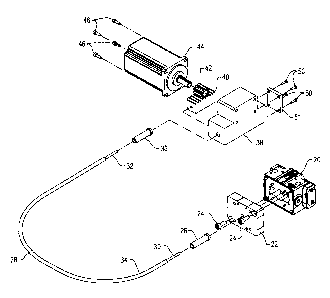
[0008] Fig. 1 is an exploded perspective view of an embodiment of the
invention;
[0009] Fig. 2 is a perspective view of an embodiment of a cable assembly of
the invention;
[0010] Fig. 3 is a cross-sectional perspective view of an embodiment of a
cable assembly of
the invention;
[0011] Fig. 4 is a multi-perspective exploded view of an embodiment of a force
transmitter of
the invention;
[0012] Fig. 5 is a perspective view of another embodiment of a cable assembly
of the
invention;
[0013] Fig. 6 is a cross-sectional perspective view of another embodiment of a
cable assembly
of the invention;
[0014] Fig. 7 is a perspective and partially cross-sectional view of another
embodiment of a
cable assembly of the invention;
[0015] Fig. 8 is an exploded perspective view of yet another embodiment of the
invention;
[0016] Fig. 9 is an exploded perspective view of yet another embodiment of the
invention;
[0017] Fig. 10 is a perspective view of yet another embodiment of a cable
assembly of the
invention;
[0018] Fig. 11 is a perspective cross-sectional view of yet another embodiment
of a cable
assembly of the invention;
[0019] Fig. 12 is a multi-perspective view of another embodiment of a force
transmitter of the
invention;
[0020] Fig. 13 is a multi-perspective view of another embodiment of a force
transmitter of the
invention; and
[0021] Fig. 14 is an exploded perspective view of yet another embodiment of
the invention.
[0022] Corresponding reference characters indicate corresponding parts
throughout the several
3
CA 02831442 2013-10-25
views. The exemplifications set out herein illustrate embodiments of the
invention and such
exemplifications are not to be construed as limiting the scope of the
invention in any manner.
DETAILED DESCRIPTION OF THE INVENTION
[0023] Referring now to the drawings, and more particularly to Fig. 1, there
is shown a gripper
which generally includes a gripper head 20 that includes the gripping jaws and
those components
responsible for moving and guiding the jaws. A cover 22 is attached to the
gripper head 20 with
threaded fasteners 24. A ferrule 26 is attached to the cover 22 by adhesive
bonding or other
suitable means. An output end 30, shown in Fig. 1 as a rod, of a cable
assembly 28 passes
through axially aligned holes in the ferrule 26 and in the cover 22 and is
attached by threading or
other suitable means to the appropriate component within the gripper head 20
responsible for
moving the gripper jaws. The opposing end of the ferrule 26 is threaded or
adhesively bonded
onto the distal end of a sheath 34 of the cable assembly 28 (see also Fig. 3).
The proximal end of
the sheath 34 is threaded or adhesively bonded into a ferrule 36. The opposing
end of the ferrule
36 is attached to a motor housing 38 by adhesive bonding or other suitable
means. An input end
32, shown as a rod, of the cable assembly 28 passes through a hole in the
motor housing 38 and
is threaded into a rack 40. A pinion 42 is engaged into the rack 40 and
coupled to the shaft of an
actuator 44, shown here as a motor, to convert the rotary motion of the motor
44 into a
corresponding linear motion of the rack 40 and in turn, into a corresponding
linear motion of the
output end 30 to move the gripper jaws. While Fig. 1 shows a linear converter
embodied as a
rack 40 and a pinion 42, those skilled in the art will appreciate that any
component capable of
converting rotary motion into linear motion can be used in the place of the
rack 40 and the pinion
42. Threaded fasteners 46 attach the motor 44 to the motor housing 38. A cover
51 is attached
with threaded fasteners 50 to close the open cavity in the motor housing 38.
4
CA 02831442 2013-10-25
[0024] Although Figs. 1-14 show and reference an actuator driving the gripper
as a rotary
electric motor, it is understood that such an embodiment may also be applied
to a gripper
including a linear electric motor, or a piston and cylinder arranged to
generate motive force. It is
also understood that the embodiment may be applied to any type or style of
gripper in order to
physically separate the components of the gripper responsible for moving and
guiding the jaws
from those components responsible for generating the motive force. It is
further understood that
such an embodiment may also be applied to actuators or end effectors other
than grippers
without changing the substance of the invention.
[0025] The cable assembly 28 can be any construction capable of transmitting
both tensile and
compressive forces, while allowing sufficient flexure to accommodate relative
motion between
the gripper head 20 and actuator. Ideally, the transmission of the tensile and
compressive forces
though the cable assembly 28 occurs with minimal or substantially no parasitic
loss so that the
majority of the force applied to the input end 32 of the cable assembly 28 is
available at the
output end 30 to move the jaws of the gripper. Such cable assemblies are used
in the steering
systems for small marine vessels.
[0026] Figs. 2, 3 and 4 show one embodiment of the cable assembly 28. Fig 3
shows a section
view along the longitudinal axis of the cable assembly 28. A short length of
the cable assembly
28 is shown for illustrative purposes and it is understood that the overall
length of the cable
assembly 28 can be increased or decreased as desired. Fig. 4 shows rendered
perspective views
of a spherical bead 53. The input end 32 and output end 30 bound a plurality
of spherical beads
53 and a cable 52, which are surrounded by a flexible sheath 34. The cable 52
can include a braid
of polymer filaments, although cables including braided or twisted metal
strands can also be
used. The proximal end of the cable 52 is adhesively bonded into a
complimentary central bore
in the input end 32. A central bore 56 in each bead 53 allows the plurality of
beads to be strung
CA 02831442 2013-10-25
along a length of the cable 52. A complimentary spherical cavity 54 on one end
of each bead 53
allows each bead 53 to nest and be nested by adjacent beads 53 so that the
column of beads
shares a common centerline. As the cable assembly 28 is laterally flexed, each
bead 53 is free to
rotate unencumbered about the center of its spherical diameter while
maintaining a common line
of contact with an adjacent bead. In this manner, the line of contact between
each adjacent pair
of beads remains normal to the radius of curvature of the flexed sheath 28.
The input end 32 and
output end 30 possess a spherical radius on one end and a complimentary
spherical cavity on the
opposing end in an analogous manner to the beads 50. The spherical radius on
the end of the
input end 32 allows the end to nest into the complimentary spherical cavity 54
on the first bead
53 on the proximal end of the cable assembly 28 and the spherical cavity on
the end of the output
end 30 allows the end to nest over the spherical radius of the last bead 53 on
the distal end of the
cable assembly 28. The distal end of the cable 52 passes through a
complimentary central bore in
the output end 30. The cable 52 is stretched to remove all clearance between
the input end 32,
beads 53 and the output end 30 and create a desired level of tension in the
cable. While in this
stretched state, the distal end of the cable 52 is adhesively bonded to the
bore in the output end
30. The tensioned column of the input and output ends 32, 30 and beads 53 is
inserted through
the inner bore of the sheath 34 to complete the cable assembly 28. The
resulting cable assembly
28 is capable of transmitting compressive force from one end of the assembly
to the other end as
each spherical bead 53 presses against an adjacent bead in the column. The
cable assembly 28 is
also able to transmit tensile force through the cable 52.
[0027] Figs. 5, 6 and 7 show another embodiment of the cable assembly 28. Fig.
6 shows a
section view along the longitudinal axis of the cable assembly 28. A short
length of the cable
assembly 28 is shown for illustrative purposes and it is understood that the
overall length of the
assembly can be increased or decreased as desired. Fig. 7 shows a partially
sectioned perspective
6
CA 02831442 2013-10-25
view of the cable assembly 28. The input end 32 and output end 30 bound a
length of a helical
extension spring 60 and a cable 52, which are surrounded by a flexible sheath
34. The cable 52
can include a braid of polymer filaments, although cables including braided or
twisted metal
strands can also be used. The proximal end of the cable 52 is adhesively
bonded into a
complimentary central bore in the input end 32. The distal end of the cable 52
passes through a
complimentary central bore in the output end 30. The cable 52 is stretched to
remove all
clearance between the input end 32, helical extension spring 60 and output end
30 and create a
desired level of tension in the cable 52. While in this stretched state, the
distal end of the cable
52 is adhesively bonded to the bore in the output end 30. The tensioned column
of the input and
output ends 32, 30 and spring 60 is inserted through the inner bore of the
sheath 34 to complete
the cable assembly 28. The resulting cable assembly 28 is capable of
transmitting compressive
force from one end of the cable assembly 28 to the other end as each spring
winding 60 presses
against an adjacent winding. The assembly is also able to transmit tensile
force through the cable
52.
100281 Fig. 8 shows another embodiment of the invention. A gripper head 20
includes the
gripping jaws and those components responsible for moving and guiding the
jaws. A cover 22 is
attached to the gripper head 20 with threaded fasteners 24. Ferrules 26 are
attached to the gripper
cover 22 by adhesive bonding or other suitable means. An output end of a cable
52 of a cable
assembly 28 passes though axially aligned holes in the ferrule 26 and in the
cover 22; wraps
tangentially around a pulley 72, and exits the cover 22 and ferrule 26 though
axially aligned
holes in the cover 22 and ferrule 26, respectively. The ferrule 26 is threaded
or adhesively
bonded onto the distal end of a sheath 34 of the cable assembly 28. The
ferrule 26 is threaded or
adhesively bonded onto the distal end of a sheath 34. The proximal end of the
sheath 34 is
threaded or adhesively bonded into a ferrule 36. Ferrules 36 are attached to a
motor cover 51 by
7
CA 02831442 2013-10-25
=
adhesive bonding or other suitable means. Threaded fasteners 50 attach the
motor cover 51 to a
motor housing 38. The input end of the cable 52 of the cable assembly 28
passes though axially
aligned holes in the ferrule 36 and in the motor cover 51; wraps tangentially
around a pulley 70,
and exits the cover 51 and ferrule 36 though axially aligned holes in the
cover and ferrule,
respectively. The pulley 70 is coupled to the shaft of an actuator 44, shown
here as a motor, to
convert the rotary motion of the motor 44 into a corresponding linear motion
of the cable
assembly cable 52, which is free to slide axially within sheath 34. Threaded
fasteners 46 attach
the motor 44 onto the motor housing 38. The ends of a shaft 74 are contained
in complimentary
grooves (not shown) in the interior of the gripper cover 22, which prevent
translation of the shaft
74 while allowing unencumbered shaft rotation. A pulley 72 and a pinion 42 are
coupled to the
shaft 74, so that rotational motion of the pulley 72 causes a corresponding
rotation of the pinion
42. The pinion 42 is engaged into a rack 40 to convert the rotary motion of
the pulley 72 into a
corresponding linear motion of the rack 40 to move the gripper jaws. The cable
52 engages the
input pulley 70 and output pulley 72 with means that prevent the tangential
movement of the
cable 52 with respect to the pulleys. In this manner, rotation of the input
pulley 70 causes a
corresponding rotation of the output pulley 72 with a quantity of torque
transmitted between the
pulleys. Although the pitch diameters of the pulleys are shown as equal in
Fig. 8, it is understood
that the ratio of the two pulley pitch diameters can be varied so as to alter
the torque and
rotational velocity transmitted between the pulleys.
[0029] The cable assembly 28 can comprise any construction capable of
transmitting only
tensile force, only compressive force, or both tensile and compressive forces,
while allowing
sufficient flexure to accommodate relative motion between the gripper head and
actuator.
Ideally, the transmission of the tensile or compressive force though the cable
assembly occurs
with minimal or substantially no parasitic loss so that the majority of the
force applied to the
8
CA 02831442 2013-10-25
input pulley 70 of the cable assembly 28 is available at the output pulley 72
to move the jaws of
the gripper. Such cable assemblies are used to control bicycle gear shifting
mechanisms.
100301 Fig. 9 shows yet another alternative embodiment of the gripper. A
gripper head 20
includes the gripping jaws and those components responsible for moving and
guiding the jaws. A
cover 22 is attached to the gripper head 20 with threaded fasteners 24. A
ferrule 26 is attached to
the gripper cover 22 by adhesive bonding or other suitable means. An output
end 30 of a cable
assembly 28 passes though axially aligned holes in the ferrule 26 and in the
cover 22 and is
attached by threading into a lead screw 80. A lead nut 82 is engaged by the
lead screw 80 with
the opposing end of the lead nut 82 attached by threading or other suitable
means to the
appropriate component within the gripper head 20 responsible for moving the
gripper jaws. The
opposing end of the ferrule 26 is threaded or adhesively bonded onto the
distal end of a sheath 34
of the cable assembly 28 (see also Fig. 3). The proximal end of the sheath 34
is threaded or
adhesively bonded into the ferrule end of a motor housing 38. An input end 32
of the cable
assembly 28 passes through a hole in the motor housing 38 and is coupled into
the shaft of an
actuator 44, shown here as a motor, to convert the rotation of the motor shaft
into a
corresponding rotation of the input end 32, output end 30 and lead screw 80.
The rotation of the
lead screw 80 is converted into a corresponding linear motion of the non-
rotating lead nut 82 to
move the gripper jaws. Threaded fasteners 46 attach the motor 44 to the motor
housing 38.
[0031] The cable assembly 28 can include any construction capable of
transmitting torque,
while allowing sufficient flexure to accommodate relative motion between the
gripper head 20
and actuator 44. Ideally, the transmission of the torque though the cable
assembly 28 occurs with
minimal or substantially no parasitic loss so that the majority of the torque
applied to the input
end 32 of the cable assembly 28 is available at the output end 30 to move the
jaws of the gripper.
Such cable assemblies are used to control automotive speedometer mechanisms.
9
CA 02831442 2013-10-25
[0032] Figs. 10, 11, 12 and 13 show an alternative embodiment of a cable
assembly 28, which
is suitable for the transmission of torque. A short length of the cable
assembly 28 is shown for
illustrative purposes and it is understood that the overall length of the
assembly can be increased
or decreased as desired. An input end 32 and an output end 30 bound a
plurality of cylindrical
couplings 90 interdisposed with a plurality of spherical couplings 92, which
are surrounded by a
flexible sheath 34. The cylindrical couplings 90 can possess a spherical
cavity on each end of a
cylindrical body. Each cavity is divided by a rectangular tab 94 with the
center of the tab 94
located coincidently with the longitudinal axis of the cylinder. The
longitudinal axis of each tab
94 is chosen to be orthogonal to that of the other tab 94. The spherical
couplings 92 possess a
spherical radius complimentary to the radius on each end of the cylindrical
couplings 90. The
spherical diameter of the spherical couplings 92 is interrupted by two
rectangular slots 96, 98
with the center of each slot located coincidently with center of the spherical
diameter. The
longitudinal axis of each slot is chosen to be orthogonal to that of the other
slot, with the width of
the slots complimentary to the width of the tabs 94 of the cylindrical
couplings 90. The
complimentary spherical radii and slot and tab widths allow alternating
spherical and cylindrical
couplings to nest and be nested by adjacent couplings with the tab of each
cylindrical coupling
90 engaging the slot of mating spherical coupling 92 so that the column of
couplings shares a
common centerline. As the cable assembly 28 is laterally flexed, each coupling
is free to rotate
unencumbered about the center of its spherical radius parallel to the
longitudinal axis of a slot or
tab, while maintaining a common line of contact with an adjacent coupling. In
this manner, the
line of contact between each adjacent pair of couplings remains normal to the
radius of curvature
of the flexed sheath 34. The engagement of slots 96, 98 and tabs 94 prevent
rotation of one
coupling around the line of contact with an adjoining coupling, allowing the
transmission of
torque between couplings along the line of contact. The input end 32 and
output end 30 possess a
CA 02831442 2013-10-25
=
=
spherical radius and complimentary slot on one end in an analogous manner to
the spherical
couplings 92. The radius and slot on the end of the input end 32 allow the end
to nest into the
complimentary spherical cavity on the first cylindrical coupling on the
proximal end of the cable
assembly 28 and the radius and slot on the end of the output end 30 allow the
output end to nest
into the complimentary spherical cavity of the last cylindrical coupling on
the distal end of the
cable assembly. The completed cable assembly 28 is thusly able to transmit
torque between the
input end 32 and output end 30 along the longitudinal axis of the cable
assembly 28.
[0033] Fig. 14 shows another embodiment of the invention. A gripper head 20
includes the
gripping jaws 100 and those components responsible for moving and guiding the
jaws. A cover
22 is attached to the gripper head 20 with threaded fasteners 24. A ferrule is
attached to the
gripper cover 22 by adhesive bonding or other suitable means, including a
clamping ferrule
design that allows easy reduction of cable length in the field. The ferrule
shown as components
26A, 26B, and 26C is a clamping style ferrule. To minimize overall height of
the assembly, the
ferrule is shown located perpendicular to the gripper body. A cam assembly
106, 108, 110
within the cover 22 transfers the motion of a cable assembly 28 to a linear
converter 104. The
cam 106, 108, 110 could be eliminated and the cable assembly 28 connected
directly to the linear
converter 104 if assembly height did not need to be minimized. An output end
30 of the cable
assembly 28 passes through the ferrule 26A, 26B, 26C and cover 22 and is
attached either to the
cam 106, 108, 110 or directly to the linear converter 104 within the gripper
head 20. The
drawing shows a swaged end fitting on the cable but any suitable means of
securing the cable
may be used. A spring 102 is positioned to push directly on either the cam
assembly 106, 108,
110 or on the linear converter 104. This spring 102 provides positive driving
force to the gripper
jaws 100 and may be used to retain the gripper jaw position in the event that
the cable assembly
28 should fail. The opposing end of the ferrule 26A, 26B, 26C is suitably
attached to the distal
11
CA 02831442 2013-10-25
end of a sheath 34 of the cable assembly 28. The proximal end of the sheath 34
is suitably
attached into the ferrule end of a motor housing 38. An input end 32 of the
cable assembly 28
passes through a hole in the motor housing 38 and is coupled to the shaft of
an actuator 44,
shown here as a motor, via a mechanism that converts the rotation of the motor
shaft to a linear
motion of an input end 32 and therefore, an output end 30. The mechanism to
convert the
actuator rotary motion to linear motion may use any suitable means, including,
but not limited to
the rack and pinion; lead screw and lead nut; or pulley systems previously
described. The
motion of the output end 30 can be converted by a corresponding linear
converter 104, either
through the cam assembly 106, 108, 110, or directly as previously mentioned,
to move the
gripper jaws 100. The motor housing 38 may also include provisions for
mounting position
sensors to infer the jaw 100 position based on the location of the end of the
cable assembly 28.
This would be useful to eliminate the need for sensors on the gripper itself,
or could be used in
conjunction with sensors on the gripper to easily detect the failure of the
cable assembly 28.
Threaded fasteners 46 attach the motor 44 to the motor housing 38. The cable
assembly 28 can
be any construction capable of transmitting tension, while allowing sufficient
flexure to
accommodate relative motion between the gripper head 20 and motor 44. Ideally,
the
transmission of the force though the cable assembly 28 occurs with minimal
parasitic loss so that
the majority of the force applied to the input end 32 of the cable assembly 28
is available at the
output end 30 to move the jaws of the gripper. Such cable assemblies are used
to control
automotive carburetor throttle mechanisms.
[0034] While this invention has been described with respect to at least one
embodiment, the
scope of the claims should not be limited by the preferred embodiments set
forth in the
examples, but should be given the broadest interpretation consistent with the
description as a
whole. This application is therefore intended to cover any variations, uses,
or adaptations of the
12
CA 02831442 2013-10-25
invention using its general principles. Further, this application is intended
to cover such
departures from the present disclosure as come within known or customary
practice in the art to
which this invention pertains and which fall within the limits of the appended
claims.
13