Language selection

Search

Patent 2831615 Summary

Third-party information liability

Some of the information on this Web page has been provided by external sources. The Government of Canada is not responsible for the accuracy, reliability or currency of the information supplied by external sources. Users wishing to rely upon this information should consult directly with the source of the information. Content provided by external sources is not subject to official languages, privacy and accessibility requirements.

Claims and Abstract availability

Any discrepancies in the text and image of the Claims and Abstract are due to differing posting times. Text of the Claims and Abstract are posted:

  • At the time the application is open to public inspection;
  • At the time of issue of the patent (grant).
(12) Patent: (11) CA 2831615
(54) English Title: A BUILDING ELEMENT FOR A STRUCTURAL BUILDING PANEL
(54) French Title: ELEMENT DE CONSTRUCTION POUR UN PANNEAU DE CONSTRUCTION STRUCTURAL
Status: Granted and Issued
Bibliographic Data
(51) International Patent Classification (IPC):
  • E04B 02/86 (2006.01)
  • E04B 02/00 (2006.01)
  • E04B 02/46 (2006.01)
  • E04C 02/34 (2006.01)
  • E04G 11/00 (2006.01)
  • E04G 11/06 (2006.01)
(72) Inventors :
  • DINCEL, BURAK (Australia)
(73) Owners :
  • BURAK DINCEL
(71) Applicants :
  • BURAK DINCEL (Australia)
(74) Agent: DEETH WILLIAMS WALL LLP
(74) Associate agent:
(45) Issued: 2018-12-18
(86) PCT Filing Date: 2012-04-10
(87) Open to Public Inspection: 2012-10-18
Examination requested: 2017-01-03
Availability of licence: N/A
Dedicated to the Public: N/A
(25) Language of filing: English

Patent Cooperation Treaty (PCT): Yes
(86) PCT Filing Number: PCT/AU2012/000358
(87) International Publication Number: AU2012000358
(85) National Entry: 2013-09-27

(30) Application Priority Data:
Application No. Country/Territory Date
2011901361 (Australia) 2011-04-11

Abstracts

English Abstract

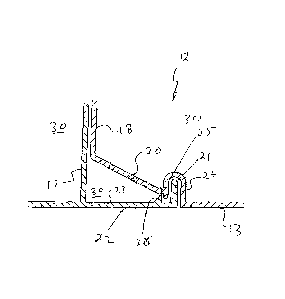
A building element (12) that is an elongated extrusion of plastics material. The element (12) can be used to form straight or curved walls (11). Like elements (12) are secured together by transverse relative movement and snap engagement of flanges (22) in recesses (21). In one embodiment the element (12) has a longitudinally extending seal projection (26) that aids in sealingly connecting engaged elements (12).


French Abstract

L'invention porte sur un élément de construction (12), qui est une extrusion allongée de matière plastique. L'élément (12) peut être utilisé pour former des parois droites ou incurvées (11). Des éléments identiques (12) sont fixés les uns aux autres par un mouvement relatif transversal et une prise d'encliquetage de brides (22) dans des creux (21). Dans un mode de réalisation, l'élément (12) comporte une saillie d'étanchéité s'étendant longitudinalement (26) qui aide à relier de façon étanche des éléments en prise (12).

Claims

Note: Claims are shown in the official language in which they were submitted.


5
CLAIMS:
1. An extruded hollow longitudinally elongated building element into which
concrete is to be poured, the building element being extruded so as to be
integrally
formed and comprising:
a pair of longitudinally, extending spaced side walls which are longitudinally
coextensive and longitudinally parallel;
a plurality of longitudinally extending spaced transverse webs joining the
side
walls, the webs including a first and a second web;
a pair of longitudinally extending grooves, each of the grooves being formed
in a
respective one of the side walls;
a pair of longitudinally extending end flanges, each of the end flanges
extending
from a respective one of the side walls;
a pair of longitudinal surfaces that diverge from the first web toward the
grooves;
a sealing projection extending from each end flange and extending
longitudinally
thereof;
wherein the end flanges each include a first portion extending from a
respective
one of the side walls, and a second portion extending transversely from the
first portion,
with the second portion of each end flange being positioned and configured to
engage a
respective one of the grooves of a respective one of the end flanges of a like
element, and
the end flanges are resiliently deformed by engagement with the longitudinal
diverging
surfaces of the like element, so that when the end flanges are moved in a
transverse
direction relative to the longitudinal diverging surfaces of the like element,
snap
engagement of each end flange is allowed in the respective one of the grooves
to thereby
secure the building element and the like element together by snap engagement,
and with
the sealing projection of each end flange extending transversely from the
respective one
of the end flanges toward the other like element to aid in sealingly
connecting the
building element and like element;
wherein the sealing projection of each end flange extends from the second
portion of that end flange; and
wherein the sealing projection is a first sealing projection and each groove
is
provided by a groove providing portion extending longitudinally of the
building element,
each groove providing portion having a further sealing projection extending
longitudinally of the building element and extending into the respective
groove so as to be

6
operatively associated with the first sealing projection of the second portion
to aid in
sealingly connecting the building element and like element.
2. The building
element of claim 1, wherein said transverse webs include a further
web located between the first and second webs.

Description

Note: Descriptions are shown in the official language in which they were submitted.


CA 02831615 2013-09-27
WO 2012/139153
PCT/AU2012/000358
1
A BUILDING ELEMENT FOR A STRUCTURAL BUILDING PANEL
Technical Field
The present invention relates to elongated hollow building elements that are
combined to form a wall or panel and more particularly to such building
elements that are
extruded for plastics material and are secured together by snap engagement.
The building
elements can be used in the construction of basement walls, liquid and
granular storage
tanks and other like structures.
Background of the invention
The present invention relates to the building element described in USA Patent
7703248.
Where walls are exposed to moisture, such as walls of water storage tanks and
building walls below ground level, typically waterproofing is applied to the
walls that are
exposed to the moisture. In the construction of conventional concrete and
reinforced
masonry walls, the walls need to be protected from moisture as exposure to
moisture over
time will cause degradation of the concrete and corrosion of the steel. A
still further
problem is mould, mildew and fungus and bacterial development on the walls. To
address this issue typically a waterproof membrane is applied to inhibit water
reaching the
concrete or reinforced masonry wall. It is also not unusual to provide a gap
between an
earth surface and the wall to enable a water proofing membrane to be applied.
Typically
the gap can be a metre. This gap can be considered a safety issue for workers.
The above construction of walls that are to exist in a damp environment has a
number of disadvantages in that if the waterproofing fails then the wall will
degrade. A
further disadvantage is the loss of floor area should a gap be required
between the wall
and an earth surface.
Object of the Invention
It is the object of the present invention to overcome or substantially
ameliorate at
least one of the above disadvantages.
Summary of the Invention
There is disclosed herein an extruded hollow longitudinally elongated building
element into which concrete is to be poured, the element being extruded so as
to be
integrally formed and comprising:
a pair of longitudinally extending spaced walls which are generally
longitudinally coextensive and longitudinally parallel;

CA 02831615 2013-09-27
WO 2012/139153
PCT/AU2012/000358
2
a plurality of longitudinally extending spaced transverse webs joining the
side
walls, the webs including a first and a second web;
a pair of longitudinally extending grooves, each of the grooves being formed
in a
respective one of the side walls;
a pair of longitudinally extending end flanges, each of the end flanges
extending
from a respective one of the walls;
a pair of longitudinally surfaces that diverge from the first web toward the
grooves;
a sealing projection extending from each flange and extending longitudinally
thereof; and wherein
the end flanges and grooves are positioned and configured to engage a
respective
one of the grooves of a respective one of the flanges of a like element, and
the end flanges
are resilient deformed by engagement longitudinal surface of the like element
so as to be
resilient deformed such that, when the end flanges are moved in a transverse
direction
relative to the diverging surfaces of the like element, there is a resilient
deformation of the
end flanges to allow snap engagement of each end flange in a respective one of
the
grooves to thereby secure the elements together by snap engagement, and the
sealing
projections extend transversely from their associated flange toward the other
element to
aid in sealingly connecting the. elements.
Preferably, each end flange includes a first portion extending transversely
from
the first wall, and a second portion extending generally transverse relative
to the first
Portion so as to project into the associated groove of the like element.
In one preferred form, said sealing element projects from said portion.
In a further preferred form, said sealing projection extends from said second
portion.
Preferably, each groove is provided by a groove providing portion extending
longitudinally of the element, the groove providing portion having a sealing
projection
extending longitudinally of the element and extending into the groove so as to
be
operatively associated with the sealing element of the second portion to aid
in sealingly
connecting the elements.

CA 02831615 2013-09-27
WO 2012/139153
PCT/AU2012/000358
3
Brief Description of the Drawings
Preferred forms of the present invention will now be described by way of
example with reference to the accompanying drawings wherein:
Figure 1 is a schematic top plan view of the walls of a building basement;
Figure 2 is a schematic top plan view of portion of one of the walls of Figure
1;
Figure 3 is a schematic top plan view of a further portion of one of the walls
of
Figure 1;
Figure 4 is a schematic top plan view of a building element used to form the
walls of the basement of Figure 1;
Figure 5 is a schematic top plan view of a further building element used in
forming the walls of Figure 1;
Figure 6 is a schematic enlarged view of portion of the elements used to form
the
walls of Figure 1; and
Figure 7 is a schematic top plan view of an alternative portion of Figure 6.
Detailed Description of the Preferred Embodiments
In Figure 1 of the accompanying drawings there is schematically depicted the
basement 10 of a building. The basement 10 may be below ground level.
The basement 10 includes walls 11 that may be straight or curved. Each of the
walls 11 is formed by a plurality of elongated building elements 12. Each
building
element 12 is hollow and is extruded from plastics material. Each element 12
has a pair
of longitudinally extending side walls 13 that are longitudinally parallel. In
Figure 3 the
element 12 illustrated has the walls 13 also transversely parallel and
generally flat. The
element 12 of Figure 5 has longitudinally extending side walls 14 and 15 that
provide for
the construction of curved walls and corners, with the walls 11 inclined by a
desired angle
29. The inner wall 15 is of a shorter transverse width relative to the outer
wall 14.
Each of the elements 12 has a plurality of transverse webs 16 and end webs 17
and 18. The webs 16 of the element 12 of Figure 4 is joined to the side walls
13 by
connecting webs 19. The connecting webs 19 are inclined so as to converge from
their
connection with the side walls 13 to the associated web 16.
The end web 18 has extending from it longitudinally extending ramp surfaces 20
=
that diverge from the web 18 toward the side walls 13, 14 and 15. The surfaces
20 extend
to longitudinally extending grooves 21.

CA 02831615 2013-09-27
WO 2012/139153
PCT/AU2012/000358
4
Extending from the end web 17 are flanges 22 that in the embodiment of Figure
4 are generally parallel and coextensive.
Like elements 12 are connected by transverse relative movement between the
elements 12. In particular the flanges 22 of one of the elements 12 moves
transversely
across the surfaces 20 so as to be resiliently deflected apart, with the
flanges 22 then snap
engaging within the recesses 21 to thereby connect adjacent elements 12.
As best seen in Figures 6 and 7 each flange 22 includes a first flange portion
23
that extends from the web 17, and a second flange portion 24 that extends from
the first
flange portion 23. The second portion 24 is to be located in the recess 21.
The portions
23 of each element 12 are generally parallel and coextensive and extend
generally
transverse to the associated web 17. The second portion 26 projects from the
first portion
23 in a direction generally parallel to the web 17.
Each groove 21 is provided by a groove providing portion 25, the portions 25
of
each element 12 being generally parallel and coextensive. The portions 25 are
of a "U"
shaped transverse cross section so as to receive the portion 24.
In the embodiment of Figure 6, the first flange portion 23 is provided with a
longitudinally extending seal projection 26 that is shaped like a barb. The
projection 26
extends from the first portion 23 toward the other element 12. The projection
26 may
actually engage the other element 12 or be slightly spaced therefrom. In such
instances, ,
wet concrete delivered to the cavities 30 would sealingly connect each sealing
projection
26 to the adjacent element 12. The projection 26 aids in sealingly connecting
engaged
elements 12.
When elements 12, as shown in Figure 6, are connected, the second portion 24
would move along the surface 20 so as to cause resilient outward deflection of
the first
portions 22 until the second portions 24 were aligned with the groove 21 so as
to snap
engage therein.
In the embodiment of Figure 7, there is provided 4 pair of sealing projections
27
and 28. The projection 27 extends from the second portion 24 while the
projection 28
extends from the recess providing portion 25. The projections 27 and 28
engage, or are
located adjacent each other so that the gap therebetween is sealed by wet
concrete.
The projections 26, 27 and 28 extend the entire longitudinal length of each of
the
elements 12.

Representative Drawing
A single figure which represents the drawing illustrating the invention.
Administrative Status

2024-08-01:As part of the Next Generation Patents (NGP) transition, the Canadian Patents Database (CPD) now contains a more detailed Event History, which replicates the Event Log of our new back-office solution.

Please note that "Inactive:" events refers to events no longer in use in our new back-office solution.

For a clearer understanding of the status of the application/patent presented on this page, the site Disclaimer , as well as the definitions for Patent , Event History , Maintenance Fee  and Payment History  should be consulted.

Event History

Description Date
Common Representative Appointed 2019-10-30
Inactive: Late MF processed 2019-05-08
Letter Sent 2019-04-10
Grant by Issuance 2018-12-18
Inactive: Cover page published 2018-12-17
Inactive: Office letter 2018-11-06
Inactive: Final fee received 2018-11-05
Pre-grant 2018-11-05
Inactive: Correspondence - PCT 2018-10-31
Notice of Allowance is Issued 2018-10-12
Letter Sent 2018-10-12
Notice of Allowance is Issued 2018-10-12
Inactive: Approved for allowance (AFA) 2018-10-10
Inactive: Q2 passed 2018-10-10
Amendment Received - Voluntary Amendment 2018-06-15
Maintenance Request Received 2018-03-27
Inactive: S.30(2) Rules - Examiner requisition 2018-01-02
Inactive: Report - QC passed 2017-12-28
Maintenance Request Received 2017-03-14
Letter Sent 2017-01-11
Request for Examination Requirements Determined Compliant 2017-01-03
All Requirements for Examination Determined Compliant 2017-01-03
Request for Examination Received 2017-01-03
Maintenance Request Received 2016-04-06
Maintenance Request Received 2015-03-24
Maintenance Request Received 2014-03-26
Inactive: Cover page published 2013-11-15
Inactive: Notice - National entry - No RFE 2013-11-06
Inactive: First IPC assigned 2013-11-05
Inactive: IPC assigned 2013-11-05
Application Received - PCT 2013-11-05
National Entry Requirements Determined Compliant 2013-09-27
Application Published (Open to Public Inspection) 2012-10-18

Abandonment History

There is no abandonment history.

Maintenance Fee

The last payment was received on 2018-03-27

Note : If the full payment has not been received on or before the date indicated, a further fee may be required which may be one of the following

  • the reinstatement fee;
  • the late payment fee; or
  • additional fee to reverse deemed expiry.

Patent fees are adjusted on the 1st of January every year. The amounts above are the current amounts if received by December 31 of the current year.
Please refer to the CIPO Patent Fees web page to see all current fee amounts.

Owners on Record

Note: Records showing the ownership history in alphabetical order.

Current Owners on Record
BURAK DINCEL
Past Owners on Record
None
Past Owners that do not appear in the "Owners on Record" listing will appear in other documentation within the application.
Documents

To view selected files, please enter reCAPTCHA code :


To view images, click a link in the Document Description column (Temporarily unavailable). To download the documents, select one or more checkboxes in the first column and then click the "Download Selected in PDF format (Zip Archive)" or the "Download Selected as Single PDF" button.

List of published and non-published patent-specific documents on the CPD .

If you have any difficulty accessing content, you can call the Client Service Centre at 1-866-997-1936 or send them an e-mail at CIPO Client Service Centre.

({010=All Documents, 020=As Filed, 030=As Open to Public Inspection, 040=At Issuance, 050=Examination, 060=Incoming Correspondence, 070=Miscellaneous, 080=Outgoing Correspondence, 090=Payment})


Document
Description 
Date
(yyyy-mm-dd) 
Number of pages   Size of Image (KB) 
Description 2013-09-26 4 238
Drawings 2013-09-26 4 75
Claims 2013-09-26 2 74
Abstract 2013-09-26 1 57
Representative drawing 2013-11-06 1 8
Claims 2018-06-14 2 57
Representative drawing 2018-11-22 1 6
Maintenance fee payment 2024-03-26 1 26
Notice of National Entry 2013-11-05 1 193
Reminder of maintenance fee due 2013-12-10 1 111
Reminder - Request for Examination 2016-12-12 1 116
Acknowledgement of Request for Examination 2017-01-10 1 176
Commissioner's Notice - Application Found Allowable 2018-10-11 1 162
Maintenance Fee Notice 2019-05-07 1 180
Late Payment Acknowledgement 2019-05-07 1 166
PCT Correspondence 2018-10-30 1 35
Courtesy - Office Letter 2018-11-05 1 46
Final fee 2018-11-04 1 39
PCT 2013-09-26 3 106
Fees 2014-03-25 1 40
Fees 2015-03-23 1 39
Maintenance fee payment 2016-04-05 1 40
Request for examination 2017-01-02 1 41
Maintenance fee payment 2017-03-13 1 40
Examiner Requisition 2018-01-01 5 368
Maintenance fee payment 2018-03-26 1 41
Amendment / response to report 2018-06-14 7 310
Maintenance fee payment 2022-03-27 1 27
Maintenance fee payment 2023-04-04 1 27