Note: Descriptions are shown in the official language in which they were submitted.
CA 02831882 2013-09-30
WO 2012/139910
PCT/EP2012/055898
1
Creasing Accessory and Method of Providing a Crease in a Substrate
The present invention relates to a creasing accessory, in particular, a
creasing
accessory for providing a crease in a substrate to be cut in a guillotine
assembly
having a clamping arrangement. A method of providing a crease in a substrate
is
also provided.
When cutting substrates such as paper, card etc. commercial printers often use
a
guillotine arrangement which cuts across the substrate in a single, controlled
cutting action to provide a neat cut at the appropriate location on the
substrate.
The location of the cut is typically determined by a manual or electronically
controlled back gauge which automatically moves the substrate to precisely the
correct position under the guillotine prior to cutting.
By way of background reference, a typical prior art guillotine assembly will
now be
described, with reference to Figs. 1 to 4 attached.
The guillotine operator first places a substrate 10 onto a cutting bed 12 such
that it
rests squarely against a back gauge 14 of the assembly (Fig. 1). Using a
computerised control panel or manual adjustment mechanism (not shown), the
operator then progresses the back gauge 14 forward until the substrate 10 is
positioned beneath a guillotine assembly 16 at the appropriate position (Fig.
2). In
order to flatten and remove any air between the substrate (which may be
stacked
in several sheets) the operator can move clamp 18 down such that it clamps the
substrate onto the cutting bed 12. In this regard, the clamp 18 can be quickly
"shuffled" up and down several times in a "clamp without cut" mode in order to
ensure that the sheet(s) of substrate rests squarely and compactly on the
cutting
bed 12. If desired, the operator may choose to attach a clamp plate 20 to the
clamp 18 in order to provide a greater clamping surface over the substrate 10.
Once the substrate is positioned correctly, the clamp 18 is held in the
clamping
position ready for cutting (Fig. 3).
CA 02831882 2013-09-30
WO 2012/139910
PCT/EP2012/055898
2
With the substrate 10 clamped in place, a metal cutting blade 22 then presses
down onto the substrate cutting through it at the appropriate location (Fig.
4). A
plastic cutting stick 24 is provided in a recess of the cutting bed 12 to
provide a
resilient cutting surface to assist with the cutting action as the cutting
blade 22 cuts
through the substrate 10. The plastic cutting stick 24 also protects the metal
cutting blade 22 from damage during the cutting action.
Once the substrate 10 has been cut, the guillotine assembly 16 returns to its
original configuration (Fig. 1) ready for the next cut.
Such guillotine assemblies are widely used in the printing industry; however,
if the
operator wishes to simply provide a crease in the substrate (to provide folds
for
brochures, leaflets, booklets etc.) without cutting through it, he must remove
the
substrate from the guillotine assembly and run it through a separate creasing
machine.
According to a first aspect of the present invention there is provided a
creasing
accessory adapted to crease a substrate in a guillotine assembly having a
clamping arrangement, the creasing accessory comprising a removable male
portion having an elongate protrusion and a removable female portion adapted
to
receive the male portion therein, and attachment means for removably securing
the
male and female portions between the clamping arrangement and a cutting bed,
such that when the guillotine assembly is operated in a clamping movement, the
male and female portions of the creasing accessory will co-act to crease
substrate
therebetween along a crease line.
Preferably the male portion is provided on the clamping arrangement of the
guillotine assembly and the female portion is provided on the cutting bed of
the
guillotine assembly.
The male portion may comprise an elongate planar strip having a ridge
protruding
therefrom. Preferably, the ridge extends along the length of the planar strip
CA 02831882 2013-09-30
WO 2012/139910
PCT/EP2012/055898
3
substantially from one end to the other. The ridge may be provided on a
leading
edge of the strip.
The ridge may comprise an L-shaped protrusion. The L-shaped protrusion may be
provided with a triangular cross section having a relatively thick base
attached to
the planar strip of the male portion and a relatively thin tip to facilitate
creasing of
the substrate whilst increasing the structural rigidity of the male
protrusion.
The male portion may comprise a plastics material.
The female portion may comprise an elongate strip of material having a groove
therein to form the elongate channel for receiving the male portion and
substrate to
be creased therein.
The female portion may comprise a plastics material dimensioned to be received
within an existing cutting stick slot of the guillotine cutting bed.
The attachment means for removably securing the female portion to the cutting
bed may comprise a friction fit between the elongate strip of material and the
cutting stick slot.
The attachment means for removably securing the male portion to the clamping
arrangement may comprise magnetic strips, double sided adhesive tape,
retaining
clips, hook and loop, or other suitable means.
The male portion is preferably adapted to mate with a clamp plate of the
clamping
arrangement.
A kit comprising at least a male portion and a plurality of female portions
according
to the first aspect of the present invention, the elongate channels in the
plurality of
female portions having different dimensions in order to provide creases of
different
dimensions as required by the particular application and substrate properties.
CA 02831882 2013-09-30
WO 2012/139910
PCT/EP2012/055898
4
According to a second aspect of the present invention there is also provided a
method of providing a crease in a substrate using a guillotine assembly having
a
clamping arrangement, the method comprising providing a removable male portion
having an elongate protrusion, providing a removable female portion to receive
the
male portion therein between the clamping arrangement and a cutting bed, and
operating the guillotine assembly in a clamping movement, such that the male
and
female portions of the creasing accessory co-act to crease the substrate
therebetween along a crease line.
Preferably, the step of providing the removable male portion and the removable
female portion on the assembly includes the step of removably attaching the
male
portion to a clamping arrangement of the guillotine assembly using suitable
attachment means, and attaching the female portion to a cutting stick slot in
the
cutting bed by way of a friction fit.
The method may also comprise utilising a back gauge of the guillotine assembly
to
move the substrate through the guillotine assembly after each successive
crease in
order to provide a plurality of creases at appropriate locations on the
substrate.
The method may also comprise the step of removing the male portion and the
female portion once creasing of the substrate is complete in order to return
the
guillotine assembly to its original, cutting and clamping configuration.
Embodiments of the present invention will now be described, by way of example
only, with reference to the accompanying drawings, in which:-
Figs. 1 to 4 are cross sectional schematic views consecutively illustrating a
prior art guillotine assembly utilising a known clamping and cutting action;
Figs. 5 to 7 are cross sectional schematic views consecutively illustrating
the
accessory of the present invention installed on the guillotine assembly of
Figs. 1 to 4, in use during a creasing operation;
CA 02831882 2013-09-30
WO 2012/139910
PCT/EP2012/055898
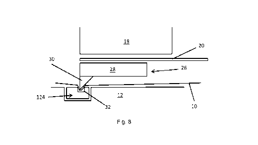
Fig. 8 is a close up view of the area A of Fig. 7 showing the creasing action
in greater detail;
Fig. 9 is a side view looking along the length of a male portion of the
accessory;
5 Fig. 10 is a perspective view of the male portion of Fig. 9;
Fig. 11 is a side view looking along the length of several female portions of
the accessory having differing widths of groove to provide a variety of
crease formations;
Fig. 12 is a perspective view of the female portion of Fig. 11.
With particular reference to Figs. 9 and 10 a male portion, generally
designated 26,
of the creasing accessory will now be described. The male portion 26 comprises
a
thin elongate attachment portion 28 having an elongate protrusion 30 running
along its leading edge.
Attachment means are provided on top of the attachment portion 28. The
attachment means in the presently described embodiment are provided by a strip
of magnetic material 34; however, it will be appreciated that many other forms
of
attachment means could be utilised; for example, double sided webbed adhesive
tape, retaining clips, hook and loop, or other suitable means. This provides a
temporary form of "quick-fit" attachment which is also easily removed when no-
longer required.
In the present embodiment, the elongate protrusion 30 takes the form of a
triangular cross sectioned ridge; however, the skilled reader will appreciate
that the
protrusion 30 could be any shape capable of providing the required creasing
effect;
for example, it could be a flat member extending at right angles from the
attachment portion 28 to form an L-shaped cross section, or alternatively it
could
comprise a raised, rounded edge etc.
CA 02831882 2013-09-30
WO 2012/139910
PCT/EP2012/055898
6
Furthermore, although the protrusion 30 is shown in the present embodiment as
a
continuous elongated ridge it could alternatively be non-continuous so as to
provide a partial crease along the substrate if required.
28 during or after manufacture of the male portion 26; however, it could
alternatively be integrally formed with the attachment portion 28.
A female portion 124 of the creasing accessory will now be described with
however, the skilled reader will appreciate that it could be any shape capable
of
providing the creasing effect; for example, it could be a V-shaped groove,
curved
groove etc. and may be chosen to correspond with the male portion 26 and or
the
substrate being creased.
The groove 32 may alternatively be provided by a notch removed from one edge
of
the female member 124 such that the groove 32 is provided by one edge of the
female member 124 and one edge of a corresponding recess wall in the cutting
bed 12.
Furthermore, although the groove 32 is shown in the present embodiment as a
continuous groove it could alternatively be non-continuous so as to provide a
partial crease along the substrate if required.
male portion 26 must be attached either directly to the clamping arrangement
18 or
onto the clamp plate 20, which is then attached to the clamping arrangement 18
in
CA 02831882 2013-09-30
WO 2012/139910
PCT/EP2012/055898
7
the normal fashion. In the presently described embodiment, the male portion 26
is
attached to the clamp plate 20 first. To achieve this, a strip of magnetic
material 34
is attached along the attachment portion 28. The male portion 26 is then
placed
onto the metal clamp plate 20 such that it is held magnetically thereto, as
best
illustrated in Fig. 8.
The cutting stick 24 which is normally in place for cutting actions, is then
removed
from its recess in the cutting bed 12 and replaced with the female portion 124
of
the creasing accessory. The outer dimensions of the female portion 124 are
geometrically similar to the cutting stick 24 in order to provide a tight fit
in the
cutting bed 12 recess, which ensures that the female portion 124 is held
secure in
the cutting bed 12 recess during creasing.
In use, and with particular reference to Figs. 7 and 8, the operator then
places the
substrate 10 against the back gauge 14 and selects the location at which a
crease
in the substrate 10 is desired. The operator then selects the guillotine's
built in
"clamp without cut" function which causes the clamp 18 to be brought down onto
the substrate 10. As it does so, the protrusion 30 on the male portion 26 is
forced
into the channel 32 of the female portion 124, trapping the substrate 10
therebetween. This causes the substrate 10 to crease along a neat, controlled
line
in a single clamp and crease action at the correct position on the substrate.
The above described creasing process is repeated along the substrate 10 until
the
required creases have been formed. This may involve turning the substrate 10
over in order to create opposite sense creases for e.g. concertina folds.
Once the creasing operation is complete, the clamp plate 20 (and hence the
male
portion 26) is removed from the clamp 18. The female portion 124 is then
removed
from the recess in the cutting bed 12 and the previously removed cutting stick
24
reinserted in order to allow normal cutting and clamping to be resumed.
CA 02831882 2013-09-30
WO 2012/139910
PCT/EP2012/055898
8
The male portion 26 can then also be removed from the clamp plate 20 with a
sliding action; the properties of the magnetic strip 34 are well suited for
this
because this ensures that the male portion 26 is held very securely onto the
face of
the clamp plate 20 during creasing whilst allowing the operator to easily
slide the
male portion 26 off the clamp plate 20 once creasing is complete.
Modifications and improvements may be made to the foregoing, without departing
from the scope of the invention, for example:-
The female portion 124 may be provided as part of a kit comprising several
female
portions having differently dimensioned grooves to allow creasing on different
substrates. These may also be colour coded to allow the operator to easily
identify
the correct strip for a particular application.
Although in the embodiment shown, the male portion is provided above, on the
clamp and the female portion is provided below, on the cutting bed, this could
be
reversed such that the male portion is provided below, on the cutting bed, and
the
female portion is provided above, on the clamp if desired.