Note: Descriptions are shown in the official language in which they were submitted.
CA 02832103 2015-01-28
22062-WO
TITLE OF THE INVENTION
IMPROVED TRIGGER SPRAYER VALVES
BACKGROUND OF THE INVENTION
[0002] Field of the Invention: Embodiments of the invention relate to trigger
sprayer
valves and more particularly to inlet and discharge valves used with trigger
sprayers, including
improved pre-compression discharge valves.
[0003] State of the Art: Trigger sprayers are well known and are commonly used
as
delivery devices to deliver a product, such as a liquid, from a container to a
surface or an area in
which the product is desired. For example, trigger sprayers may be used to
apply cleaning agents
to hard surfaces or to deliver air freshener to a volume of air. The use and
applications for such
devices are well known.
[0004] A conventional trigger sprayer typically includes a valve body having
an inlet
and an outlet. A pump chamber may be formed in the valve body and a piston may
be seated in
the pump chamber and moveable therein to alter the volume of the pump chamber.
A piston is
typically attached to a trigger and the trigger, piston, or both trigger and
piston may be biased by
a spring. An inlet valve in communication with the valve body inlet and the
pump chamber
regulates the flow of product into the pump chamber. Similarly, an outlet
valve seated between
the pump chamber and the valve body outlet regulates flow of a product out of
the pump
chamber and through the valve body outlet. The valve body may be attached to
or in
communication with a container holding a product. The connection may be made
with a closure
system such as a bayonet system integrated with the valve body or a screw
connection mated
with the valve body as known in the art.
[0005] Examples of trigger sprayers are illustrated and described in U.S.
Patent
5,467,900, U.S. Patent 7,175,056 and PCT Publication W02010124040.
1
CA 02832103 2013-10-02
WO 2012/161813
PCT/US2012/026695
2
[0006] While
there are numerous trigger sprayer designs available in the market,
improvements and new designs are continually being developed. For example, new
all-
plastic designs may be desirable so that the trigger sprayer may be easily
recycled. New
designs may also offer improved economics or reduced material weight and part
counts. In
other instances, it may be desirable for a trigger sprayer to include a pre-
compression feature
which allows for the build-up of pressure prior to the release of a product
through an outlet
valve such that the pressure build-up is such that a sufficient force is
applied to the product
being dispensed to create a desired spray pattern or to achieve finer particle
sizes upon
dispensing. Pre-compression systems may also be desirable for other reasons.
An example
of a pre-compression valve system for a trigger sprayer is described and
illustrated in U.S.
patent 5,467,900. Improvements in such pre-compression valves may enhance the
performance or user acceptance of a trigger sprayer.
[0007] In still other instances, it may be desirable to have a trigger sprayer
valve
body design which may be fitted with either a pre-compression valve system for
those
applications desiring pre-compression or a non-pre-compression valve system
for use when
pre-compression is not desired.
BRIEF SUMMARY OF THE INVENTION
[0008] According to certain embodiments of the invention, various pre-
compression systems are incorporated with a trigger sprayer to provide a pre-
compression
option for a trigger sprayer.
[0009] According to some embodiments of the invention, a trigger sprayer may
include a two piece discharge valve. A first valve component may be seated on
a valve seat
and held in position by a frame. The frame may interlock with, attach to, or
be otherwise
secured to the valve body of the trigger sprayer to secure the valve on the
valve seat.
[0010] According to other embodiments of the invention, a trigger sprayer
valve
body may be configured to accept a pre-compression valve or a non-pre-
compression valve
such that a trigger sprayer having a pre-compression option may be made from a
majority of
the same parts used for a non-pre-compression version of the same trigger
sprayer.
[0011] In some embodiments of the invention, a trigger sprayer may include an
option for a pre-compression discharge valve or a non-pre-compression
discharge valve. In
certain embodiments, a pre-compression discharge valve may include a bi-
injected, two
material discharge valve. In other embodiments, a bi-injected discharge valve
may be made
of the same material having different stifthess, rigidity, or other features
and characteristics.
2
CA 02832103 2013-10-02
WO 2012/161813 PCT/US2012/026695
3
In still other embodiments, a pre-compression discharge valve may include a
valve member
and a frame member.
BRIEF DESCRIPTION OF THE DRAWINGS
[0012] While the specification concludes with claims particularly pointing out
and
distinctly claiming particular embodiments of the present invention, various
embodiments of
the invention can be more readily understood and appreciated by one of
ordinary skill in the
art from the following descriptions of various embodiments of the invention
when read in
conjunction with the accompanying drawings in which:
[0013] FIG. 1 illustrates a cross-sectional view of a trigger sprayer
according to
various embodiments of the invention;
[0014] FIG. 2 illustrates a cross-sectional view of a trigger sprayer
according to
various embodiments of the invention;
[0015] FIG. 3 illustrates a cross-sectional view of a trigger sprayer
according to
various embodiments of the invention;
[0016] FIG. 4 illustrates a blown apart view of a valve body and discharge
valve
according to embodiments of the invention;
[0017] FIG. 5 illustrates a rear view of a discharge valve assembled with a
valve
body according to various embodiments of the invention;
[0018] FIG. 6 illustrates a cross-sectional view of a discharge valve
according to
various embodiments of the invention;
[0019] FIG. 7 illustrates a cross-sectional view of a discharge valve
according to
various embodiments of the invention;
[0020] FIG. 8 illustrates a discharge valve according to various embodiments
of the
invention;
[0021] FIG. 9 illustrates a discharge valve according to various embodiments
of the
invention;
[0022] FIG. 10 illustrates a cross-sectional view of a discharge valve
assembled
with a valve body and inlet valve according to various embodiments of the
invention;
[0023] FIG. 11 illustrates a cross-sectional view of a discharge valve
assembled
with a valve body and shroud according to various embodiments of the
invention;
[0024] FIG. 12 illustrates a cross-sectional view of a trigger sprayer
according to
various embodiments of the invention;
3
CA 02832103 2013-10-02
WO 2012/161813 PCT/US2012/026695
4
[0025] FIG. 13 illustrates a valve and plug system according to various
embodiments of the invention;
[0026] FIG. 14 illustrates a plug according to various embodiments of the
invention;
[0027] FIG. 15 illustrates a plug according to various embodiments of the
invention;
[0028] FIG. 16 illustrates an exploded-view of a trigger sprayer according to
various embodiments of the invention;
[0029] FIG. 17 illustrates a cross-sectional view of a trigger sprayer
according to
various embodiments of the invention;
[0030] FIG. 18 illustrates a close-up view of a portion of the trigger sprayer
illustrated in FIG. 17;
[0031] FIG. 19 illustrates a cross-sectional view of a trigger sprayer
according to
various embodiments of the invention;
[0032] FIG. 20 illustrates a close-up view of a portion of the trigger sprayer
illustrated in FIG. 19;
[0033] FIG. 21 illustrates a cross-sectional view of a valve body according to
various embodiments of the invention;
[0034] FIG. 22 illustrates a close-up view of a portion of the valve body
illustrated
in FIG. 21;
[0035] FIG. 23 illustrates a front-view of a valve body according to various
embodiments of the invention;
[0036] FIG. 24 illustrates a valve according to various embodiments of the
invention;
[0037] FIG. 25 illustrates a side-view of a valve according to various
embodiments
of the invention;
[0038] FIG. 26 illustrates a cross-sectional view of a valve according to
various
embodiments of the invention;
[0039] FIG. 27 illustrates a valve according to various embodiments of the
invention;
[0040] FIG. 28 illustrates a side-view of a valve according to various
embodiments
of the invention;
[0041] FIG. 29 illustrates a cross-sectional view of a valve according to
various
embodiments of the invention;
4
CA 02832103 2013-10-02
WO 2012/161813
PCT/US2012/026695
[0042] FIG. 30 illustrates a discharge valve according to various embodiments
of
the invention;
[0043] FIG. 31 illustrates a cross-sectional view of a discharge valve
according to
various embodiments of the invention;
[0044] FIG. 32 illustrates a cross-sectional view of a discharge valve
according to
various embodiments of the invention;
[0045] FIG. 33 illustrates a discharge valve according to various embodiments
of
the invention;
[0046] FIG. 34 illustrates a discharge valve according to various embodiments
of
the invention;
[0047] FIG. 35 illustrates a cross-sectional view of a frame of a discharge
valve
according to various embodiments of the invention;
[0048] FIG. 36 illustrates a cross-sectional view of a frame of a discharge
valve
according to various embodiments of the invention;
[0049] FIG. 37 illustrates a cross-sectional view of a valve body according to
various embodiments of the invention;
[0050] FIG. 38 illustrates a front-view of a valve body according to various
embodiments of the invention;
[0051] FIG. 39 illustrates a close-up view of a portion of the valve body
illustrated
in FIG. 37;
[0052] FIG. 40 illustrates a front-view of an inlet valve according to various
embodiments of the invention;
[0053] FIG. 41 illustrates a side-view of an inlet valve according to various
embodiments of the invention;
[0054] FIG. 42 illustrates a rear-view of an inlet valve according to various
embodiments of the invention;
[0055] FIG. 43 illustrates an inlet valve according to various embodiments of
the
invnetion;
[0056] FIG. 44 illustrates an inlet valve according to various embodiments of
the
invention;
[0057] FIG. 45 illustrates an inlet valve according to various embodiments of
the
invention;
[0058] FIG. 46 illustrates a cross-sectional view of an inlet valve according
to
various embodiments of the invention;
5
CA 02832103 2013-10-02
WO 2012/161813 PCT/US2012/026695
6
[0059] FIG. 47 illustrates an inlet valve according to various embodiments of
the
invention; and
[0060] FIG. 48 illustrates a cross-sectional view of an inlet valve according
to
various embodiments of the invention.
DETAILED DESCRIPTION OF THE INVENTION
[0061] According to various embodiments of the invention, a trigger sprayer
may
include a discharge valve which allows a pressure build-up or pre-compression
prior to the
unseating of the discharge valve. In some embodiments of the invention, a
valve body may
be configured to accept either a discharge valve capable of providing pre-
compression to the
trigger sprayer or a valve and plug for use in those applications where pre-
compression is not
desired.
[0062] A trigger sprayer 100 according to some embodiments of the invention is
illustrated in FIG. 1. As illustrated, a trigger sprayer 100 may include a
valve body 110. The
valve body 110 may include an inlet 112 and an outlet 114. The inlet 112 and
outlet 114 may
be in communication with a pump chamber 113. A piston 120 may be seated in the
pump
chamber 113. An inlet valve 130 may be seated in a valve seat between the
inlet 112 and the
pump chamber 113. A discharge valve 140 may be seated in a valve seat between
the pump
chamber 113 and the outlet 114. In some embodiments, a tube retainer 118 may
integrally
formed with the valve body 110 as illustrated. In other embodiments, a tube
retainer may fit
into a portion of the valve body 110. A nozzle 160 may be fitted or mated with
the valve
body 110 as known. The trigger sprayer 100 may also include a shroud 190
attached to or
mated with the valve body 110 and an attachment system 192 for securing the
trigger sprayer
100 to a container. The attachment system 192 may include a bayonet attachment
system
molded with the valve body 110, a bayonet attachment system molded in a
separate part, a
screw-type attachment system molded as a separate part, or any other
conventional
attachment system. The trigger sprayer 100 may also include a dip tube 194
secured in a tube
retainer 118.
[0063] A trigger 152 and spring 154 may also be included as part of a trigger
sprayer 100. While an integrated trigger 152 and spring 154 combination is
illustrated in
various figures herein, it is understood that various embodiments of the
invention may
incorporate other trigger 152 and spring 154 combinations, including such
combinations
where the trigger 152 and spring 154 are not integrated as a single component.
For example,
6
CA 02832103 2013-10-02
WO 2012/161813 PCT/US2012/026695
7
a conventional trigger and metal coil spring or plastic spring may be used
with various
embodiments of the invention.
[0064] According to embodiments of the invention, the discharge valve 140 may
be
made of a flexible material having the ability to flex or deform upon the
exertion of a certain
amount of force on the discharge valve 140. For example, the material used for
a discharge
valve 140 may be selected based upon the desired discharge force. In some
embodiments the
discharge valve 140 may be made of an elastomeric material. In other
embodiments, the
discharge valve 140 may be made of a flexible material, a plastic material, a
urethane
material, a silicon material or any other desired material.
[0065] As illustrated in FIG. 1, a discharge valve 140 may be seated in a
valve seat
in the valve body 110. The valve seat may be located in a top portion of the
valve body 110
such that during assembly a discharge valve 140 may be seated in the valve
seat opening in
the valve body 110. A shroud 190 may then be assembled to the valve body 110
and a
portion of the shroud 190 may secure the discharge valve 140 in its seated
position. As
product is pumped out of the pump chamber 113 it may contact the discharge
valve 140 and
apply a pressure against the discharge valve 140. According to various
embodiments of the
invention, the discharge valve 140 will maintain a seal against the valve seat
until a pre-
determined pressure is reached at which time the discharge valve 140 will
unseat and allow
product to pass by the discharge valve 140 and towards the outlet 114.
[0066] A trigger sprayer 100 according to other embodiments of the invention
is
illustrated in FIG. 2. As illustrated, the trigger sprayer 100 includes a
valve body 110 having
an inlet 112 and an outlet 114. An inlet valve 130 may be seated in a valve
seat between the
inlet 112 and the pump chamber 113. A discharge valve 140 may be seated in a
valve seat
between the pump chamber 113 and the outlet 114. As illustrated in FIG. 2, the
valve seat for
the discharge valve 140 may be located in a rear portion of the valve body 110
rather than on
a top portion of the valve body 110 as illustrated in FIG. 1.
[0067] The discharge valve 140 of the trigger sprayer 100 illustrated in FIG.
2 may
be retained within the valve seat in part by a portion of the shroud 190. As
the trigger 152 is
actuated, the piston 120 is moved in the pump chamber 113, applying force to
the product in
the pump chamber 113 which in turn applies force to the discharge valve 140.
Once the force
on the discharge valve 140 reaches a force capable of unseating the discharge
valve 140, the
discharge valve unseats and allows product to pass the discharge valve 140 and
flow to the
outlet 114.
7
CA 02832103 2013-10-02
WO 2012/161813 PCT/US2012/026695
8
[0068] As with the discharge valve 140 illustrated in FIG. 1, the discharge
valve
140 illustrated in FIG. 2 may be made of a flexible or elastomeric material.
The material of
the discharge valve 140 may be selected to provide particular characteristics
to the discharge
valve 140, such as a sufficient rigidity or stiffness to prevent deformation
or movement of the
discharge valve 140 until a certain amount of force or pressure is applied to
the discharge
valve 140. In some embodiments, the discharge valve 140 may also be shaped or
engineered
to provide desired characteristics. For example, the thickness of material may
be altered or
varied or ribs or other supporting structures may be designed as part of the
discharge valve
140 to achieve the desired characteristics.
[0069] A trigger sprayer 100 according to other embodiments of the invention
is
illustrated in FIG. 3. While the configuration of the valve body 110 is
similar to other
embodiments of the invention, the discharge path from the pump chamber 113 to
the outlet
114 may be configured differently and the discharge valve 240 may include a bi-
injected
discharge valve 240 assembly or multi-component discharge valve 240 assembly.
[0070] For example, a cross-sectional view of a discharge valve 240 according
to
various embodiments of the invention is illustrated in FIGS. 6 and 7 and a
discharge valve
240 is illustrated in FIGS. 8 and 9. Assembly of a discharge valve 240 with a
valve body 110
according to various embodiments of the invention is illustrated in FIGS. 4
and 5.
[0071] According to various embodiments of the invention, a discharge valve
240
may include a frame 242 and a valve 244 as illustrated in FIGS. 4 through 9.
The frame 242
and valve 244 may be bi-injected or formed of multiple components. According
to some
embodiments of the invention, a frame 242 may be formed of polypropylene or
other plastic
material. According to some embodiments of the invention, a valve 244 may be
formed of an
olefin based polymer, silicon, other polymer material, or plastic material.
While various
materials for the frame 242 and valve 244 are described herein, other
materials may also be
used and the various embodiments of the invention are not limited by the
selection of
materials for the discharge valve 240.
[0072] A discharge valve 240 according to various embodiments of the invention
may have a valve 244 bi-injected or mated with a frame 242 such that the frame
242 may
support the valve 244. For example, as illustrated in FIGS. 8 and 9, a valve
244 may be
encompassed by and supported by the frame 242. As illustrated in FIGS. 6 and
7, a portion
of the valve 244 may sit within an opening in the frame 242 and a portion of
the valve 244
may wrap around a portion of the frame 242. When assembled to a valve body 110
as
illustrated in FIGS. 4 and 5, the frame 242 may secure the valve 244 in a
seated position on a
8
CA 02832103 2013-10-02
WO 2012/161813 PCT/US2012/026695
9
portion of the valve body 110. According to some embodiments of the invention,
a frame
242 may also include features to help secure the frame 242 to the valve body
110. For
example, a frame 242 may include snap beads, locking projections or other
configurations
which allow the frame 242 to be secured to the valve body 110. A valve body
110 may also
include features to help retain a frame 242 to the valve body 110 when
assembled.
[0073] A close-up, cross-sectional view of a discharge valve 240 assembled
with a
valve body 110 according to various embodiments of the invention is
illustrated FIG. 10. As
shown, a discharge valve 240 may be assembled to a valve body 110. The valve
244 portion
of the discharge valve 240 may be seated against an outlet portion 111 of the
valve body 110.
Upon the flow of a product through the outlet portion 111 of the valve body
110, the product
may apply a force against the valve 244 seated against the outlet portion 111.
Such pressure
may flex the valve 244 or cause the valve 244 to move such that a product may
pass by the
discharge valve 240 and the outlet 114 of the trigger sprayer 100.
[0074] As illustrated, the frame 242 of the discharge valve 240 may secure the
valve 244 in a seated position. Once sufficient pressure on the valve 244 is
removed, the
valve 244 may reseat on the outlet portion 111 of the valve body 110. The
frame 242 may
help retain the valve 244 in the proper position. For example, the positioning
of the frame
242 with respect to the valve body 110 may secure the valve 244 in a position
that prevents
blow-outs of the valve 244. The frame 242 may prevent such blow-outs because
the valve
244 is retained upstream of the outlet portion 111 by the frame 242. Thus,
when the valve
244 is opened it is stretched and may be pulled back to a seated position by
the elastic
characteristics or features of the valve 244 material. Such a configuration
may provide
improved seating for a pre-compression valve.
[0075] A discharge valve 240 may be secured to a valve body 110 in various
ways.
According to some embodiments of the invention, a discharge valve 240 may be
secured as
illustrated in FIG. 11. In some embodiments, the frame 242 of a discharge
valve 240 may
include projections which may mate with or contact projections or tabs on a
valve body 110.
The contact of the projections may hold a frame 242 in place during operation
of a trigger
sprayer 100. In other embodiments, a shroud 190 may also hold the discharge
valve 240 in
place or assist with the mating of a discharge valve 240 with a valve body
110. As illustrated
in FIG. 11, a shroud 190 may frictionally fit against a frame 242 of a
discharge valve 240 to
retain or help retain the frame 242 in communication with a valve body 110.
The positioning
of portions of the shroud 190 around the frame 242 or against the frame 242
may secure the
frame 242 in an assembled position. In addition, a frame 242 may include
projections which
9
CA 02832103 2013-10-02
WO 2012/161813 PCT/US2012/026695
mate with a shroud 190 or a shroud 190 may include projections that mate with
the frame 242
such that the frame 242 and shroud 190 may be locked or mated together.
[0076] Although a discharge valve 240 according to certain embodiments of the
invention may be bi-injected, a discharge valve 240 may also be assembled from
two or more
parts. For example, the frame 242 may be molded and assembled with a valve 244
which is
molded separately. The frame 242 and valve 244 may be snap-fit together,
welded together,
glued together, or otherwise assembled as a single discharge valve 240
assembly. In other
embodiments, a frame 242 and valve 244 may not be connected but instead press-
fit or
friction fit together or in a sealing configuration during assembly with a
valve body 110,
shroud 190, or other components of a trigger sprayer 100.
[0077] A trigger sprayer 100 according to other embodiments of the invention
is
illustrated in FIG. 12. As illustrated, a trigger sprayer 100 according to
embodiments of the
invention may include a valve 130 having both an inlet valve and an outlet
valve. For
example, a valve system such as that disclosed in U.S. Patent 7,175,056 may be
used with
various embodiments of the invention. Such a valve system may be used for a
trigger sprayer
100 which does not or may not include a pre-compression system. However, such
a valve
system may be used with a valve body 110 similar to or identical to the valve
body 110 used
with other embodiments of the invention.
[0078] According to embodiments of the invention, a trigger sprayer 100 may
include a plug 340 in place of a discharge valve 240. A plug 340 may seal an
opening in the
valve body 110 where a discharge valve 240 could be placed and may allow a
product
discharged from a pump chamber 113 to flow past the plug towards the outlet
114. Thus, a
valve body 110 according to various embodiments of the invention may be used
to assemble
either a pre-compression type trigger sprayer 100 as illustrated in FIG. 3 or
a non-pre-
compression type trigger sprayer 100 as illustrated in FIG. 12. For example,
if a pre-
compression type trigger sprayer 100 is desired, a valve body 110 may be
assembled with a
discharge valve 240 according to embodiments of the invention. If a non-pre-
compression
type trigger sprayer 100 is desired, a valve body 110 may be assembled with a
valve 130
having an inlet valve and an outlet valve and a plug 340 may be used in place
of the
discharge valve 240.
[0079] A cross-sectional, close-up view of a valve 130 and plug 340
combination
assembled with a valve body 110 is illustrated in FIG. 13.
[0080] A plug 340 according to embodiments of the invention may be made of any
desired material and in any desired shape. A plug 340 design according to
certain
CA 02832103 2013-10-02
WO 2012/161813 PCT/US2012/026695
11
embodiments of the invention is illustrated in FIGS. 14 and 15. As
illustrated, a plug 340
may include features similar to a discharge valve 240 in that it may include
projections or
other features which may be used to secure a plug 340 to a valve body 110. The
configuration or shape of the plug 340 may also be altered to fit the valve
body 110 as desired
and to provide a product flow path from the pump chamber 113 to the outlet
114.
[0081] An exploded view of a trigger sprayer 400 according to still other
embodiments of the invention is illustrated in FIG. 16. As shown, a trigger
sprayer 400 may
include an assembly of a valve body 410, an inlet valve 430, an actuator 450,
a piston 420, a
nozzle 460, a shroud 490, an attachment system 492, a dip tube 494, and a
discharge valve
440. As illustrated in FIG. 16, the discharge valve 440 may include a frame
442 and a valve
444 wherein the frame 442 may attach to or snap-fit with the valve body 410
and may secure
the valve 444 on, against, or in proximity to a valve seat of the valve body
410.
[0082] Conventional methods may be used to assemble a trigger sprayer 400 such
as that illustrated in FIG. 16 and components such as the nozzle 460, shroud
490, attachment
system 492, dip tube 494, piston 420, actuator 450 and valves may be assembled
as desired.
In addition, a trigger sprayer 400 according to embodiments of the invention
may be
assembled to a bottle or other container as desired and known in the art. For
example, a
screw-on attachment system 492 may be used to attach a trigger sprayer 400 to
a bottle
having a corresponding screw-type thread system. In other examples, a valve
body 410 may
include a bayonet-type attachment system 492 which may be mated with and
attached to a
bottle or container having corresponding bayonet connectors.
[0083] A cross-sectional view of an assembled trigger sprayer 400 according to
some embodiments of the invention is illustrated in FIG. 17. As illustrated,
the trigger
sprayer 400 is in a non-actuated position having a piston 420 seated in a
variable volume
pump chamber 422. A portion of an inlet valve 430 is seated against a pump
chamber inlet
423 and a portion of a discharge valve 440 is seated against a pump chamber
outlet 425.
[0084] A blown-up view of the inlet valve 430 and discharge valve 440
encompassed by the dotted lines in FIG. 17 is illustrated in FIG. 18. As
illustrated, an inlet
valve 430 may be seated in a pump chamber 422 with an inlet valve member 433
seated
against a pump chamber inlet 423. A valve 444 of a discharge valve 440 may be
seated
against a valve seat 470 surrounding the pump chamber outlet 425 as
illustrated. A frame
442 may secure the valve 444 against the valve seat 470 and in a position of
contact with the
valve body 410. One or more outer edges 449 of the valve 444 may contact the
valve body
410 and form a seal therewith.
11
CA 02832103 2013-10-02
WO 2012/161813 PCT/US2012/026695
12
[0085] A cross-sectional view of an assembled trigger sprayer 400 according to
embodiments of the invention is illustrated in FIG. 19. As illustrated, the
trigger sprayer 400
may be in an actuated or partially actuated position wherein a piston 420 has
moved within a
pump chamber 422, reducing the volume therein and forcing product through the
pump
chamber outlet 425 such that the valve 444 of the discharge valve 440 is
unseated from the
valve seat 470.
[0086] A blown-up view of the discharge valve 440 encompassed by the dotted
lines in FIG. 19 is illustrated in FIG. 20. As illustrated, when a piston 420
is moved in a
pump chamber 422 by actuation of the trigger sprayer 400, the piston forces
fluid or product
through the pump chamber outlet 425, past valve 444 and into the discharge
passageway or
outlet 414 as illustrated by the bold fluid flow path line in FIG. 20. As the
piston 420 moves
within the pump chamber 422, the chamber size is reduced and any fluid or
product within
the pump chamber 422 passes into the pump chamber outlet 425 to encounter the
valve 444.
Once a certain pressure on the valve 444 is reached ¨ the cracking pressure ¨
the valve 444
may unseat from the valve seat 470, allowing fluid or product to flow past the
valve 444 and
into the discharge passageway or outlet 414.
[0087] A cross-sectional view of a valve body 410 of a trigger sprayer 400
according to various embodiments of the invention is illustrated in FIG. 21. A
valve body
410 may be configured in a conventional manner and may include a pump chamber
422
which may be defined by an opening in the valve body 410 and a piston 420
inserted in the
opening. The pump chamber 422 may include a pump chamber inlet 423 and a pump
chamber outlet 425. Fluid or product may flow from an inlet 412 of the valve
body 410
through the pump chamber inlet 423 into the pump chamber 422 and out through
the pump
chamber outlet 425 into the discharge passageway or outlet 414 of the valve
body 410. In
some embodiments of the invention, a pump chamber outlet 425 may be in direct
communication with the outlet 414 or may be in indirect communication such as
illustrated in
FIG. 21 wherein the pump chamber outlet 425 opens to an opening in the valve
body 410
which is in communication with the outlet 414. In some embodiments of the
invention, the
pump chamber outlet 425 may be centered along an axis which is parallel to an
axis of the
outlet 414. In other embodiments of the invention, the pump chamber outlet 425
may be
centered along an axis which is perpendicular to an axis of the outlet 414. In
still other
embodiments of the invention, the pump chamber outlet 425 may be centered
along an axis
that is neither parallel to nor perpendicular to the axis of the outlet 414.
12
CA 02832103 2013-10-02
WO 2012/161813 PCT/US2012/026695
13
[0088] According to various embodiments of the invention, a discharge valve
seat
470 may be located at an exit of, or end of, the pump chamber outlet 425 as
illustrated in
FIGS. 18 and 21 through 23. In some embodiments, the valve seat 470 may
include a
circular shape as illustrated. In other embodiments, the shape of the valve
seat 470 may be
selected as desired.
[0089] A close-up of the valve seat 470 and pump chamber outlet 425 designated
by broken lines in FIG. 21 is illustrated in FIG. 22. In some embodiments of
the invention,
the valve seat 470 may include one or more features to facilitate sealing of
the valve seat 470
with a valve 444. For example, a valve seat 470 may include a sealing ring,
one or more lips,
one or more flashes, one or more nipples, or other features configured to mate
with or seal
with a valve 444. A valve seat 470 may also include a rim which contacts a
valve 444
making a seal therewith. In some embodiments of the invention, the valve seat
470 may
include a sloped interior surface such as that illustrated in FIGs. 21 and 22
which may
facilitate positioning of a portion of a valve 444 in or against the valve
seat 470. For
example, a close-up view of a discharge valve 440 in an assembled trigger
sprayer 410
according to various embodiments of the invention is illustrated in FIG. 18.
As illustrated, a
valve lip 447 seats or contacts an interior of the valve seat 470. As the
valve 444 is
assembled to the valve body 410, the valve lip 447 may make contact with the
sloped interior
surfaces of the valve seat 470 and the corresponding slope on the valve lip
447 may facilitate
sealing of the valve 444 with the valve seat 470 at an end of the pump chamber
outlet 425.
Upon actuation of a trigger sprayer 400, the valve 444 may unseat from the
valve seat 470 as
illustrated in FIG. 20.
[0090] A valve 444 for use with various embodiments of the invention is
illustrated
in FIGs. 24 through 26. As illustrated, a valve 444 according to various
embodiments of the
invention may be circular in shape and may include a number of different
surfaces. In some
embodiments of the invention, a valve 444 may include a circular body 446
terminating in an
outer circumference having one or more outer edges 449 or sealing surfaces.
The body 446
may have a thickness Tv as illustrated between the lines in FIG. 26. The
thickness Tv may
also vary along the surface of the body 446. For example, the thickness Tv may
vary where
other features occur along the surface of the body 446 such as at a location
of a valve lip 447
or an outer surface having one or more outer edges 449.
[0091] As illustrated in FIGs. 24 through 26, a valve 444 may include two
outer
edges 449. The circumference along the one or more outer edges may be
identical or
different. In addition, a portion of the body 446 between one or more outer
edges 449 may
13
CA 02832103 2013-10-02
WO 2012/161813 PCT/US2012/026695
14
have a smaller circumference than a circumference of the one or more outer
edges 449. For
example, as illustrated in FIGs. 24 through 26, a trough or depression exists
between a first
outer edge 449 and the second outer edge 449, wherein the circumference around
the bottom-
most point in the depression is less than the circumference around one or more
of the outer
edges 449.
[0092] As illustrated in FIGs. 24 through 26, a valve 444 may also include one
or
more valve lips 447. A valve lip 447, according to various embodiments of the
invention,
may include one or more surfaces configured to mate with one or more surfaces
of a valve
seat 470 on a pump chamber outlet 425. As illustrated in FIGs. 24 through 26,
a valve lip
447 may include a sloping surface configured to mate with a valve seat 470.
According to
various embodiments of the invention, a valve lip 447 may be shaped or
configured to seal
against a valve seat 470 to prevent the flow of a product past the valve lip
447 until a certain
force or pressure against the valve 444 is reached. The slope or shape of the
valve lip 447
may ensure a seal against a valve seat 470. For example, as illustrated in
FIG. 24, a valve lip
447 may be circular in shape and may include one or more sloping surfaces
which may mate
with, or seal with, a circular valve seat 470 on a valve body 410. A valve lip
447 may seat
within, or seal with, an interior portion of a valve seat 470 or a pump
chamber outlet 425.
[0093] In certain embodiments of the invention, a valve 444 may also include
one
or more valve stems 448. As illustrated in FIGs. 24 through 26, a single valve
stem 448 may
be included with certain embodiments. A valve stem 448 may extend outwards
from a body
446 on one or both sides of the body 446. As illustrated, a valve stem 448 may
be
perpendicular to the body 446. In other embodiments, a valve stem 448 may
extend away
from a body 446 at another angle. According to some embodiments of the
invention, a valve
stem 448 may configured or shaped to facilitate the assembly of a valve 444
with a trigger
sprayer 400. In some embodiments, a valve stem 448 may extend through a
portion of a
frame 442.
[0094] A valve 444 having a valve lip 447 seated against a valve seat 470 is
illustrated in FIG. 18. As illustrated, when a valve 444 is seated in an
assembled trigger
sprayer 400, the valve lip 447 may seat against or seal against the valve seat
470. The seating
of the valve lip 447 against the valve seat 470 and the positioning of the
valve 444 in the
trigger sprayer 400 may cause the body 446 to flex as illustrated in FIG. 18.
Flexion of the
body 446 may apply pressure on the valve lip 447 to assist with the sealing of
the valve 444.
In addition, pressure on the valve 444 due to placement within the trigger
sprayer 400 may
apply pressure to the one or more outer edges 449 of the valve 444, sealing
the one or more
14
CA 02832103 2013-10-02
WO 2012/161813 PCT/US2012/026695
outer edges 449 to the valve body 410 such that product in a discharge
passageway or outlet
414 may not leak past the valve 444 and into other portions of the trigger
sprayer 400.
[0095] Upon actuation, a valve 444 and body 446 may be deformed as illustrated
in
FIG. 20, allowing product to flow past the valve 444. Upon the application of
pressure or
force against the valve 444 caused by actuation of the trigger sprayer 400,
the one or more
valve lips 447 may unseat from the valve seat 470. Movement of the body 446
may be
stopped by the positioning of the frame 442 next to the valve 444. For
example, as illustrated
in FIG. 20, a back portion of the body 446 may contact the frame 442 such that
continued
flexion or movement of the body 446 is stopped and the fluid flow passage past
the valve 444
is fixed. Upon a decrease in the pressure applied to the valve 444, the valve
444 may return
to the non-actuated position illustrated in FIG. 18, stopping the flow of
fluid or product past
the valve 444.
[0096] A valve 444 for use with various embodiments of the invention is
illustrated
in FIGs. 27 through 29. The illustrated valve 444 is similar to the valve
illustrated in FIGs.
24 through 26, however, the valve 444 illustrated in FIGs. 27 through 29 has a
greater
thickness T.
[0097] A body 446 according to various embodiments of the invention may
include
a thickness Tv of about 0.50 millimeters (0.019 inches). In other embodiments,
a thickness Tv
may be about 0.80 millimeters (0.032 inches). While any thickness Tv may be
used with
embodiments of the invention, in some embodiments, a body 446 may have a
thickness Tv of
between about 0.40 millimeters (0.015 inches) and about 0.90 millimeters
(0.036 inches).
According to other embodiments of the invention, a body 446 may have a
thickness Tv of
between about 0.25 millimeters (0.009 inches) and about 1.25 millimeters (0.05
inches).
According to still other embodiments of the invention, a thickness Tv along
the body 446 may
vary, including thicker portions and thinner portions as desired. The
thickness Tv of the body
446 may be selected or designed to provide a desired resistance or minimum
cracking
pressure needed to unseat the one or more valve lips 447 from a valve seat
470.
[0098] A valve 444 according to various embodiments of the invention may be
made of any desired material. In some embodiments, a valve 444 may be formed
of an
elastic material or material capable of deforming and returning to a non-
deformed state. In
certain embodiments, a valve 444 may be formed of an olefin based polymer,
silicon, other
polymer material, or plastic material. While various materials are described,
other materials
may also be used and the various embodiments of the invention are not limited
by the
selection of materials for the valve 444.
CA 02832103 2013-10-02
WO 2012/161813 PCT/US2012/026695
16
[0099] A discharge valve 440 including a frame 442 and valve 444 combination
according to various embodiments of the invention is illustrated in FIGs. 30
through 32. As
illustrated, a valve 444 may be a part of, molded with, or connected to a
frame 442 as
illustrated. A valve 444 may include one or more valve lips 447 and one or
more outer edges
449. In some embodiments of the invention, the one or more valve lips 447 may
seat with a
valve seat 470 of a trigger sprayer to form a seal therewith. In addition, the
one or more outer
edges 449 may contact a portion of a valve body 410 to form a seal therewith.
[0100] Cross-sectional views of the discharge valve 440 illustrated in FIG. 30
are
illustrated in FIGs. 31 and 32 as represented by the cross-section lines in
FIG. 30.
[0101] A discharge valve including a frame 442 and valve 444 combination
according to other embodiments of the invention is illustrated in FIGs. 33 and
34. As
illustrated, a valve 444 may be connected to, bi-injected with, snapped to, or
otherwise
secured to a frame 442. A frame 442 may include one or more latches 443 which
may be
configured to snap to, latch with, or otherwise secure to a valve body 410.
The latching of a
frame 442 to a valve body 410 may help retain a valve 444 in position such
that a valve lip
447 may seat against a valve seat 470. One or more outer edges 449 may also be
positioned
against a valve body 410 and held in position by a frame 442 latched to a
valve body 410.
According to some embodiments of the invention, a frame 442 may include two
latches 443
such as the opposing latches illustrated in FIGs. 33 through 36.
[0102] A frame 442 according to some embodiments of the invention is
illustrated
in FIGs. 35 and 36. A frame 442 may be made of any desirable material; for
example, a
frame 442 according to certain embodiments of the invention may be molded of a
plastic or
resin material. A frame 442 may include one or more latches 443 extending
therefrom. A
latch 443 may be configured to secure to a valve body 410. Any type of latch
or securing
system may be used to secure a frame 442 to a valve body 410 as desired.
[0103] In some embodiments of the invention, a valve 444 may be secured to the
frame 442 as illustrated in FIGs. 30 through 34. According to other
embodiments of the
invention, a frame 442 may be assembled with a valve 444 such that a valve 444
is held
between a valve body 410 and the frame 442 as illustrated in FIGs. 18 and 20.
[0104] According to certain embodiments of the invention, a frame 442 may
include a frame rim 441 as illustrated. A frame rim 441 may include a
circular, or other
shaped, opening through which a portion of a valve 444, such as a valve stem
448, may
extend. According to various embodiments of the invention, a frame rim 441 may
stop a
valve 444, or portion of a valve 444, from moving along an axis of the valve
444 during
16
CA 02832103 2013-10-02
WO 2012/161813 PCT/US2012/026695
17
actuation of a trigger sprayer 400. For example, as illustrated in FIG. 20,
when actuated, a
valve 444 or body 446 portion may flex such that the one or more valve lips
447 unseat from
a valve seat 470. The frame rim 441 may stop the movement of the body 446 or
valve 444
such that a fixed opening size or flow path through the valve seat 470 and
past the valve 444
is available. In addition, a frame rim 441 may decrease the wear on a valve
444 as it limits
the extension or flexion of the valve 444 during actuation.
[0105] As illustrated in FIG. 20, a frame 442 may also assist with the seating
of the
one or more outer edges 449 against a valve body 410. The frame 442 may hold
the one or
more outer edges 449 of the valve 444 in position within the trigger sprayer
400 such that the
outer edges 449 seal against the valve body and help to retain the valve 444
in a position to
allow the valve 444 to stop the flow of product from a piston chamber when a
trigger sprayer
400 is not being actuated.
[0106] A valve body 410 according to other embodiments of the invention is
illustrated in FIGs. 37 and 39. As illustrated, the valve body 410 may include
an alternative
configuration for accepting an alternative inlet valve 430. A valve body 410
may include a
pump chamber inlet 423 and a pump chamber outlet 425 similar to other
embodiments of the
invention. A valve seat 470 may also be included on one end of the pump
chamber outlet
425. The valve body 410 may be configured to retain one or more of the inlet
valves 430
illustrated in FIGs. 40 through 50.
[0107] An inlet valve 430 according to some embodiments of the invention is
illustrated in FIGs. 40 through 43. As illustrated, an inlet valve 430 may
include an inlet
valve member 433 configured to sit in, or seat against, a pump chamber inlet
423 and act as a
valve into the pump chamber. An inlet valve 430 may also include a valve arm
435
supporting the inlet valve member 433. The valve arm 435 may be flexible such
that the inlet
valve member 433 may move in response to operation of a trigger sprayer 400.
The valve
arm 435 may also include one or more valve arm openings 434. The one or more
valve arm
openings 434 may allow the valve arm to flex or may be sized and shaped to
alter the amount
of force required to flex the valve arm 435 to move the inlet valve member
433. An inlet
valve 430 may also include one or more posts 436 which may secure within one
or more
openings of a valve body 410 to secure the inlet valve 430 within a pump
chamber.
[0108] An inlet valve 430 according to other embodiments of the invention is
illustrated in FIGs. 43, 45 and 46. As illustrated in FIG. 43, an inlet valve
430 may include a
circular support structure, three valve arms 435 and an inlet valve member 433
connected to
the three valve arms 435. Each of the three valve arms 435 may flex and may
allow
17
CA 02832103 2013-10-02
WO 2012/161813 PCT/US2012/026695
18
movement of the inlet valve member 433. The inlet valve member 433 may also
include a
valve seal 437 which may seal against a portion of a pump chamber inlet 423 to
form a seal
therewith.
[0109] Alternative views of the inlet valve 430 illustrated in FIG. 43 are
illustrated
in FIGs. 45 and 46.
[0110] An inlet valve 430 according to still other embodiments of the
invention is
illustrated in FIGs. 44, 47 and 48. As illustrated in FIG. 44, an inlet valve
430 may include a
circular support structure, two valve arms 435 and an inlet valve member 433
connected to
the two valve arms 435. Each of the two valve arms 435 may flex and may allow
movement
of the inlet valve member 433. The inlet valve member 433 may also include a
valve seal
437 which may seal against a portion of a pump chamber inlet 423 to form a
seal therewith.
[0111] Alternative views of the inlet valve 430 illustrated in FIG. 44 are
illustrated
in FIGs. 47 and 48.
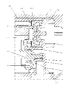
[0112] According to various embodiments of the invention, a circular support
structure of an inlet valve 430 may snap into, connect to, fit into, or
otherwise be connected
to a valve body 410 such that an inlet valve member 433 may sit or seal with a
pump
chamber inlet 423 to prevent the flow of fluid through the pump chamber inlet
423 during
actuation of a trigger sprayer 400 and to allow fluid flow through the pump
chamber inlet 423
upon return of the piston 420 from an actuated to a non-actuated position
within the pump
chamber.
[0113] While various embodiments of an inlet valve 430 are illustrated with
two
and three valve arms 435, it is understood that various embodiments of the
invention may
include more than two or three valve arms 435.
[0114] According to various embodiments of the invention, an inlet valve 430
may
be made of a flexible material. For example, an inlet valve 430 may be made of
silicon,
rubber, an olefin based polymer, a urethane based polymer, or other polymer
materials.
[0115] While various materials are disclosed herein for use in forming
discharge
valves and plugs, it is understood that embodiments of the invention are not
limited to the use
of such materials and that any desirable material may be selected for use with
the various
embodiments of the invention.
[0116] With the pre-compression systems of the various embodiments of the
invention, higher cracking pressures for the discharge valve 140, 240, 440 are
desired to
improve the pre-compression effects on a product being pumped. However, as the
cracking
pressure of a discharge valve 140, 240, 440 is increased, the ability of a
trigger sprayer 100 to
18
CA 02832103 2013-10-02
WO 2012/161813 PCT/US2012/026695
19
prime is reduced. In order to overcome such issues, the compression ratio
during priming
may need to be improved. In order to improve the compression ratio of the
trigger sprayers
100 according to various embodiments of the invention, a piston 120 may be
configured or
shaped to improve the compression ration. In some embodiments, for example, a
rear portion
of the piston 120, or the portion of the piston 120 in contact with a product
within a pump
chamber 113, in each of FIGS. 1, 2, 3, 9 and 10 is shaped or includes geometry
which
conforms to or approximates the shape and geometry of the valve body 110 and
inlet valve
130 on the interior of the pump chamber 113. By altering the geometry of the
piston 120
portion within the valve chamber 113 to match, or closely resemble, the
geometry of the
valve body 110 and inlet valve 130 within the pump chamber 113, the
compression ratio of
the trigger sprayer 100 may be improved or maximized. The improved compression
ratio
resulting from the conforming geometries of the piston 120 and geometries
within the pump
chamber 113 allows trigger sprayers 100 according to embodiments of the
invention to prime
even when the discharge valves 140, 240, 440 have higher cracking pressures.
[0117] Having thus described certain particular embodiments of the invention,
it is
understood that the invention defined by the appended claims is not to be
limited by
particular details set forth in the above description, as many apparent
variations thereof are
contemplated. Rather, the invention is limited only be the appended claims,
which include
within their scope all equivalent devices or methods which operate according
to the principles
of the invention as described.
19