Note: Descriptions are shown in the official language in which they were submitted.
CA 02832363 2013-10-04
WO 2012/136227 PCT/DK2012/050119
1
A guardrail
The invention relates to a guardrail for protecting persons
being present on open floors of buildings or scaffolds against
accidentally falling out of the opening of such floors. The
guardrail comprises a number of constructional elements and
connectors for assembling said constructional elements to a
coherent guardrail.
The invention also relates to a method for assembling said
guardrail.
The term constructional element is within the context of the
present invention a device which has a relatively large extent
in two dimensions and a relatively little thickness in the
third dimension and which is preferably without any opening or
at least without any openings large enough for allowing a
person to pass through.
During erecting of some multi-storey building are the outer
walls around a floor often not yet built. A similar situation
exists during erection of scaffolds.
Persons such as workers being present on such open floors need
to be safely protected against accidentally falling out of the
openings of the floors so that they do not risk to be seriously
injured when hitting e.g. the ground below.
Many attempts have during the years been made to solve this
important problem with the result that various kinds of
guardrails to be attached to or close to the edge of the
respective floors have been developed.
Such guardrails consist normally of a number of vertical posts,
which each is releasable attached to an open floor at an edge
CA 02832363 2013-10-04
WO 2012/136227 PCT/0K2012/050119
2
of this, and of a number of horizontal rails, which each is
releasable attached to the posts.
US Patent No. 4,787,475 discloses a guardrail of this kind. A
disadvantage of this known guardrail is however that a number
of openings are left between the posts and the rails. Said
openings are unfortunately large enough to allow a person
accidentally to falling out of the openings.
Also tools and other objects could accidentally fall out of
said openings and hit persons below whereby those persons could
be seriously injured since such tools and objects often are
relatively heavy.
Another disadvantage of said known guardrail consists in the
fact that the posts and rails of this are relatively long and
therefore troublesome and dangerous to handle within an often
narrow space close to the edge of the open floor.
Since such open floors often are relatively inaccessible and
placed at a relatively high level the long posts and rails are
moreover difficult to transport up to such floors and down
again to the ground.
The posts and rails of this known guardrail are furthermore
assembled by means of connections such as hinges, which make
the guardrail unstable and easy to destroy.
It is furthermore difficult to connect the cross-joints between
the posts and rails of the known guardrail because it during
the assembling of the guardrail is necessary to manually hold
the long rails in the required horizontal position.
Owing to the lots of such connections to be carried out for
assembling the post and rails to a finished guardrail extending
CA 02832363 2013-10-04
WO 2012/136227 PCT/0K2012/050119
3
along the edges of an open floor is the assembling of the
guardrail also very time consuming.
Such guardrails are normally used only within a limited period
of time after which the guardrails need to be dismantled again
and removed from the floor whereby the above-mentioned problems
appear again but in the inversed order.
The drawbacks and disadvantages of the above-mentioned
guardrail for protecting persons being present on open floors
of buildings or scaffolds against accidentally falling out of
the opening of such floors with the risk of seriously being
injured and/or injuring other people are according to the
invention remedied by,
in a first aspect, according to the invention, providing a
guardrail of the kind mentioned in the opening paragraph, which
is arranged for effectively being able to protect persons and
objects being present on an open floor of e.g. a building or a
scaffold to fall out of said opening,
in a second aspect, according to the invention, providing a
guardrail of the kind mentioned in the opening paragraph, which
has a stable structure,
in a third aspect, according to the invention, providing a
guardrail of the kind, mentioned in the opening paragraph,
which is assembled of guardrail elements in such a way that the
elements cannot accidentally be taken apart,
in a fourth aspect, according to the invention, providing a
guardrail of the kind mentioned in the opening paragraph, which
has a cheap and simple structure,
CA 02832363 2013-10-04
WO 2012/136227 PCT/0K2012/050119
4
in a fifth aspect, according to the invention, providing a
guardrail of the kind mentioned in the opening paragraph, which
quickly and easily can be assembled and disassembled again,
in a sixth aspect, according to the invention, providing a
guardrail of the kind mentioned in the opening paragraph, which
is composed of elements which are adapted to easily being
brought forwards and backwards between e.g. a stock of elements
and the open floor where the elements are intended to be
assembled and disassembled again, and
in a seventh aspect, according to the invention, providing a
guardrail of the kind mentioned in the opening paragraph, which
is composed of elements which can be assembled to a guardrail
fitting to the width and height required for a specific opening
of a given open floor.
The novel and unique features according to the invention
whereby this is achieved consists in the fact that the
connectors comprise at least one first connector, which has a
longitudinal shape and is formed with at least one longitudinal
extending slot and at least one second connector consisting of
a first connector part to be connected to the constructional
element and a second connector part to connect the first
connector part to the first connector while engaging the slot
of this.
This guardrail offer persons present upon an open floor a more
secure protection against falling out of the openings of such
open floors than hitherto known.
This important advantage is obtained by the fact that the flat
constructional elements of the guardrail effectively exclude
any presence of openings in the finished guardrail large enough
to allow a person to pass.
CA 02832363 2013-10-04
WO 2012/136227 PCT/0K2012/050119
The guardrail has moreover a simple and cheep construction,
which quickly and easily can be assembled to a coherent
structure and afterwards be dismantled again.
5 The particular construction of the guardrail implies, according
to the invention, that the first connectors each can be formed
with a relatively short length so that the first connectors
easily and without any risk can be transported up to an open
floor and down again.
Such relatively short length of the first connectors makes it,
according to the invention, moreover safe to assemble the
guardrail on an even narrow place close to the edge of an open
floor.
In an expedient embodiment of the invention the slots of the
first connectors each can be a T-slot and the first connector
part of the second connector be a fitting, which is adapted to
be connected to the constructional element while the second
connector part of the second connector can be a screw joint for
screwing the fitting to the first connector with the nut or
head of the screw of the screw joint placed in said T-slot
whereby a strong and durable connection between the first
connector and the constructional element quickly and easily can
be established.
The T-slot can be replaced with e.g. a dovetail slot or a slot
with any other kind of shape, where the opening of the slot is
more narrow than the bottom of the slot, thereby ensuring that
the second connector can be secured to the first connector
without piercing the first connector.
According to the invention the guardrail can quickly and easily
be assembled to a strong and stable structure, which fits to be
placed at the edge of an open floor, when the constructional
element is formed with a flange and the first connector part,
6
such as the fitting mentioned above, is formed with a hook
adapted for catching said flange.
The guardrail can likewise quickly and easily be disassembled
again in the opposite order after having served for effectively
protecting persons on the open floor against accidentally
falling out of the openings of the floor. Such accident is
especially very dangerous when the floor is placed at a high
level.
A simple structure of the assembled guardrail is obtained when
the constructional elements each has a quadratic or rectangular
shape with four edges.
That shape is imparting the guardrail also with a highly
conspicuous appearance, which clearly indicates the position of
the edges of an open floor. Persons present on such open floors
are thereby able to adapt themselves to this important
knowledge so that they can watch their steps.
Each of the constructional elements of the guardrail can,
according to the invention, simply be formed as a plate or
alternatively as a net extending between a peripheral frame.
In a preferred embodiment according to the invention can each
of the constructional elements moreover be formed as the
closure known from the inventor's patent publication no. WO
2005/031087 A.
Said known closure serves for temporary closing an opening in a
building being built, rebuilt or renovated and consists in the
main of a rectangular frame with a changeable size and a pane,
which can be mounted in the frame in any size of this.
CA 2832363 2018-06-27
CA 02832363 2013-10-04
WO 2012/136227 PCT/0K2012/050119
7
By means of this known constructional element is the guardrail
of the invention advantageously able to adapt its size to the
size of the opening of a given open floor.
The height of the frame can according to the invention moreover
be changed in such way that the guardrail extends all the way
between two succeeding open floors whereby is achieved that the
guardrail forms a wall enclosing the room behind the wall so
that the room during the cold periods of the year
advantageously can be heated to a temperature comfortable for
staying in the room.
In a preferred embodiment of the invention each of the first
connectors can be a tube section, which advantageously can be
used as posts in the finished guardrail.
When a relatively short tube section is not long enough for
serving as a post in a specific guardrail can a post that is
long enough, according to the invention, be made of two or more
tube sections placed in continuation of each other.
A guardrail placed on an open floor and thereby its posts,
which are that part of the guardrail, which is attached to the
open floor, can be influenced by transverse forces from e.g.
the wind and/or from persons accidentally hitting the guardrail
with their body whereby bending stresses would arise in the
posts.
For being able to resist such bending stresses two consecutive
placed first connectors, such as the tube sections mentioned
above, can according to the invention be connected to each
other by means of a third connector consisting of a bar, which
covers the mouth of the slot, such as the T-slot or dovetail
slot of the tube section, along a length of both first
connectors and is screwed onto the first connectors by means of
CA 02832363 2013-10-04
WO 2012/136227 PCT/0K2012/050119
8
screws having their head or nut placed in the slots of both
first connectors.
The above-mentioned third connector between two consecutive
placed tube sections is, according to the invention,
advantageously securing the relatively long post of two or more
relatively short tube sections against being bent too much in
the interface between the tube sections and especially
effectively if two opposite sides of the tube sections are
secured in that way.
By not aligning the horizontal edges of the constructional
elements with the interface between two consecutive placed tube
sections is furthermore obtained the advantage that the
strength against being bent in the interface between two
consecutive placed tube sections is increased by the strength
against being bent of the associated constructional element
itself.
A guardrail and thereby the posts of the guardrail can be
influenced by upwards directed forces too whereby tensile
stresses would arise in the posts.
For being able to resist such tensile stresses two consecutive
placed first connectors, e.g. the tube sections mentioned
above, can according to the invention be connected to each
other by means of a fourth connector, e.g. a rod, where the rod
is extending at least along a part of a guide formed in the
interior of both of the two consecutive placed first connectors
whereby the fourth connector can be anchored to both of two
consecutive placed first connectors by means of pins, e.g.
shanks of screws extending through flushing openings in the
fourth connector and the wall of the guide.
In an expedient embodiment of the fourth connector, such as the
rod, for connecting two consecutive placed first connectors,
CA 02832363 2013-10-04
WO 2012/136227 PCT/0K2012/050119
9
such as tube sections, the fourth connector can be a length of
a tube, which has the required moment of inertia without using
too much material.
According to the invention the guardrail can be assembled by
connecting consecutive placed first connectors, such as tube
sections, to each other and connecting the constructional
elements to said interconnected first connectors.
The invention will be explained in greater details below,
giving further advantageous features and technical effects and
describing exemplary embodiments with reference to the drawing,
in which
Fig. 1 is an exploded view, seen in cross section, of a segment
of the guardrail according to the invention,
Fig. 2 shows the same, but in assembled state,
Fig. 3 is a lateral view of a constructional element according
to the invention,
Fig. 4 is a cross section of the same,
Fig. 5 is a longitudinal section of an embodiment of a segment
of the guardrail according to the invention,
Fig. 6 shows the same, but seen from the front,
Fig. 7 is a longitudinal section of another embodiment of a
segment of the guardrail according to the invention,
Fig. 8 is a lateral view of a fragment of an assembled
guardrail according to the invention,
CA 02832363 2013-10-04
WO 2012/136227 PCT/0K2012/050119
Fig. 9 shows a part of a cross section of a second embodiment
of a segment of the guardrail according to the invention, and
Fig. 10 shows across section view of a third embodiment of the
5 first connector according to the invention.
The guardrail seen in the figures serves for preventing persons
being present on open floors of buildings or scaffolds against
getting hurt by falling out of the opening of such floors.
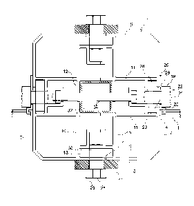
The constructional element 1 is in this case (shown in fig. 3
and 4) formed as a quadratic or rectangular plate 3 with a
flange 4 extending along the periphery of the plate, whereby
the flange is formed with a first flap 5, perpendicular to the
plate and a second flap 6, perpendicular to the first flap.
The element may e.g. be integrally made of e.g. metal or
plastic or be a plate of e.g. metal, plastic or wood with a
separate flange attached to the edge of the plate.
Within the scope of the invention the element can also be
formed as a net fastened to a peripheral frame, (not seen).
The tube section 2 shown in fig. 1 and 2 has in this case a
mainly quadratic cross section with pairs of opposite sides 7
and 8.
Within the scope of the invention may the cross section of the
tube section have other shapes, (not shown in fig. 1 and 2).
The tube section 2 has an outer wall 9 and two pairs of inner
walls 10 and 11, which are extending between each their pair of
opposite sides 7 and 8 and are intersecting each other so that
a central inner tube 12 is formed in the tube section.
CA 02832363 2013-10-04
WO 2012/136227 PCT/0K2012/050119
11
The outer wall 9 of the tube section 2 is at each side 7 and 8
formed with a longitudinally extending T-slot 13 with an
opening 14 in the outer wall of the tube section and a bottom
15 which extends between each pair of the inner walls 10 and 11
of the tube section 2 and is formed with a longitudinally
extending recess 16.
Flushing holes 17 and 18 are moreover formed in the bottom of
the longitudinally extending recess 16 of the T-slot 13 and in
the pair of inner walls of the central inner tube 12.
The tube sections 2 serve as posts 2 in the assembled guardrail
seen in fig. 8 whereby a constructional element 1, as seen in
fig. 2 and in fig. 7 in fragment, are connected with a post 2
by means of in this case a screw joint 19 and a fitting 20
whereby the screw joint 19 consists of a screw 21 with a head
22, a shank 23 and a nut 24 and the fitting 20 is formed with a
hook 25 and a through hole 26.
The connection between the constructional element 1 and the
post 2 takes quickly and easily place by placing either the nut
24 or head 22 of the screw 21 of the screw joint 19 in the T-
slot 13 of the tube section 2, connecting the flange 4 of the
constructional element 1 to the hook 25 of the fitting 20,
pushing the shank 23 of the screw 21 through the hole 26 in the
fitting 20 and tighten the screw joint 19.
The performed connection between the constructional element 1
and the tube section 2 complies effectively with the demands
required of a guardrail mounted upon an open floor.
The connection is moreover releasable so that a guardrail on an
open floor quickly and easily can be dismantled and removed
from the floor after having been used.
CA 02832363 2013-10-04
WO 2012/136227
PCT/0K2012/050119
12
As previously mentioned the tube sections 2 can each have a
relatively short length whereby is obtained the advantage that
said tube sections easily and without any risk can be
transported up to an open floor and down again.
Another advantage obtained by using such relatively short tube
sections consist in the fact that they are easy and safe to
handle at an even narrow place close to an edge of an open
floor, (not seen) of a building, (not seen) or a scaffolding,
(not seen).
When a relatively short tube section is not long enough for
serving as a post in a specific guardrail can a post that is
long enough be made of two or more tube sections placed in
continuation of each other as seen in figs. 5 to 8.
The posts 2 of the guardrail are as seen in fig. 8 attached to
an open floor 31 where the guardrail easily can be influenced
by crossway acting forces from wind and/or from persons
accidentally hitting the guardrail with their body. Said forces
are transmitted to the posts 2 whereby heavy bending stresses
can arise in the posts.
Each post of the guardrail consists in fig. 8 of two
consecutive placed tube sections, which however not themselves
are able to resist the above-mentioned heavy bending stresses
in the interface between the two tube sections.
That serious problem is remedied by means of the connection
between the two tube sections shown in 5 and 6, where fig. 5
shows a longitudinal section of the two tube sections 2 placed
in continuation of each other and fig. 6 shows the same, but
seen from the front. Said connection is shown also in cross
section in fig. 2.
CA 02832363 2013-10-04
WO 2012/136227 PCT/0K2012/050119
13
The two tube sections 2 are connected to each other at their
opposite sides 8-8 by means of lengths of a bars 27, which
cover the openings 14 of the T-slots 13 along a length of both
tube sections and is screwed onto the T-slots of both tube
sections by means of screws 28 having their head 29 or nut 30
placed in the T-slots of both tube sections as seen also in the
cross section shown in fig. 2.
This connection between the two tube sections of the post of
the guardrail is in a simple and effective way advantageously
imparting the two tube sections the necessary strength against
being bent in the interface between the two tube sections.
The guardrail shown in fig. 8 can be influenced also by upwards
acting forces when being in position on the open floor 31.
These forces are transmitted to the posts, since the posts are
those parts of the guardrail, which are attached to the floor.
In fig. 8 consist each post of two consecutive placed tube
sections 2.
In preparation for preventing that said upwards acting forces
are pulling the two tube sections of each post from each other
is a length of, in this case a tube 32 as seen in fig. 2 and 7,
placed in the inner tube 12 in the tube section 2 with a part
in each of the inner tubes of the two tube sections.
The inner tube 12 and the length of tube 32 are in this case
formed with quadratic cross sections, as seen in fig. 1 and 2.
Within the scope of the invention the cross section of e.g. the
inner tube 12 can have other shapes, for example an octagonal
shape as seen in fig.9.
The length of tube 32 is formed with holes 33 flushing with
both the holes 17 in the bottom of the longitudinally extending
recess 16 of the T-slot 13 of the tube sections 2 and the holes
18 in the inner walls 10-10 of the tube section 2 and is
CA 02832363 2013-10-04
WO 2012/136227 PCT/0K2012/050119
14
anchored in both sections 2 by means of screw bolts 34 pushed
through the holes 17, 18, 33 with their head 35 and nut 36
placed in the longitudinally extending recess 16 of two
opposite placed T-slots of the tube section 2.
Fig. 7 shows a length of a tube 37, which is formed with the
same cross section as the length of tube 32 but in this case
with a shorter length.
The length of tube 37 is mounted in the inner tube 12 in the
tube section 2 in the same way as the length of tube 32 but at
the bottom of the tube section 2 and it serves for connecting
the tube section 2 with a base plate 38 for attaching the tube
section 2 to the open floor 31.
Fig. 7 also shows a constructional element 1, seen in fragment,
which is attached to the tube section 2 in the same way as
discussed above with reference to fig. 2.
It is noted that the interface between the two tube sections 2
is not flushing with the interface between two consecutive
placed constructional elements 1 whereby the constructional
elements themselves advantageously are increasing the bending
moment of the interface between the two tube sections, which
form the posts of the guardrail of the invention.
Fig. 9 is a cross section of another embodiment of a tube
section 39 of the invention and of another embodiment of a
length of tube 40 for interconnecting two consecutive placed
tube sections, which in assembled state constitute a post of
the guardrail of the invention.
The lengths of tube 40 have in this case an octagonal shape,
seen in section but can for example also have a quadric shape,
(not shown).
CA 02832363 2013-10-04
WO 2012/136227 PCT/0K2012/050119
The tube section 39 is formed with four T-slots 41, which have
the same shape as the T-slots 13 shown in fig. 1 and 2. The
tube section 39 differs however from the tube section 2 in that
it is without pairs of inner walls.
5
The tube 40 is anchored in the length direction in the tube
section 39 by means of screw bolts 43, which have their head 44
and nut 45, placed in the recesses 42 of opposite T-slots 41.
10 In the previously mentioned fig. 8, which shows a fragment of a
guardrail, are the constructional elements of that kind, which
are known from the inventor's patent publication no. WO
2005/031087 A, but here only schematically shown.
15 Said known constructional elements comprises each a frame 46
adapted to change its height and width in accordance with the
desired height and length of a given guardrail of which the
element constitutes a part. A panel 47 is releasable mounted in
the frame 46 in such way that the frame is allowed to change
its height and length.
As seen in fig. 8 the size of the known elements is in this
case adjusted in such way that the guardrail extends all the
way between two succeeding open floors whereby the guardrail
form a wall enclosing the room behind the wall.
The guardrail of the invention does in this way not only serve
for protecting persons against accidentally falling down but
serves advantageously also for temporarily keeping out rain,
snow and wind and during the cold period of the year for
keeping the heat inside the building.
The guardrail in form of the wall serves moreover for
preventing unauthorized persons from gaining access to the room
behind the wail.
CA 02832363 2013-10-04
WO 2012/136227 PCT/0K2012/050119
16
The panel can be made of e.g. wood or glass. In fig. 8 are such
shown two rows of the known constructional elements of which
the panel of the uppermost row can be made of glass and the
lowermost of wood.
Thereby is obtained a guardrail which both is strong and
advantageously also allow the daylight to fall into the room
behind the wall.
It is noted that all the panels of the shown guardrail can be
made of glass, and that the guardrail also can comprise more
rows of constructional elements placed on top of each other.
In fig. 9 is also seen that the tube section In this case Is
connected with two constructional elements which form a right
angle with each other whereby is achieved the advantage that
the guardrail continuously can follow the edge of a quadratic
or rectangular open floor.
The above-mentioned embodiment of a post of the guardrail of
the invention is cost saving since it is made of lesser
material simultaneously with that the moment of inertia of the
length of tube 40 is large enough to impart two consecutive
placed tube section the necessary strength against being bent
in the interface between the two tube sections.
Fig. 10 shows a third embodiment of a tube section 48 of the
invention, which section at least in the main corresponds to
the first embodiment 2 of the invention. Same parts therefore
are denoted with same numerals. In this third embodiment of the
tube section 48 is the bottom 15 and the recess 16 of the
longitudinal extending T-slot 13 however left out whereby a
simpler and more inexpensive tube section advantageously is
achieved.