Note: Descriptions are shown in the official language in which they were submitted.
CA 02832495 2013-10-04
WO 2012/142571 PCT/US2012/033768
SAMPLE CAPTURE IN ONE STEP FOR TEST STRIPS
BACKGROUND OF THE INVENTION
Field of the Invention:
[0001] The present invention relates generally to the collection of body
fluid and
more specifically, the use of sample capture with a test strip to provide one
step to
obtain body fluid and analyte measurement.
Description of Related Art:
[0002] The treatment of diabetes requires frequent monitoring of levels
of blood
glucose. This is traditionally done in a series of steps involving the
preparation of a
lancing device, preparation of a glucose meter, lancing a finger, transporting
the
resulting blood drop to the meter, and finally obtaining a blood glucose
reading.
[0003] Lancing devices are known in the medical health-care products
industry for
piercing the skin to produce blood for analysis. Biochemical analysis of blood
samples is
a diagnostic tool for determining clinical information. Many point-of-care
tests are
performed using capillary whole blood, the most common being monitoring
diabetic
blood glucose level. Other uses for this method include the analysis of oxygen
and
coagulation based on Prothrombin time measurement. Typically, a drop of blood
for this
type of analysis is obtained by making a small incision in the fingertip,
creating a small
wound, which generates a small blood droplet on the surface of the skin.
[0004] Early methods of lancing included piercing or slicing the skin
with a needle or
razor. Current methods utilize lancing devices that contain a multitude of
spring, cam
and mass actuators to drive the penetrating member. These include cantilever
springs,
diaphragms, coil springs, as well as gravity plumbs used to drive the
penetrating
member. Typically, the device is pre- cocked or the user cocks the device. The
device is
held against the skin and mechanically triggers the ballistic launch of the
penetrating
member. The forward movement and depth of skin penetration of the penetrating
member is determined by a mechanical stop and/or dampening, as well as a
spring or
cam to retract the penetrating member. Spontaneous blood droplet generation is
dependent on reaching the blood capillaries and venuoles, which yield the
blood
sample.
[0005] As lancing devices have become more advanced, so they have become
more complex, using lower and lower volumes of blood or body fluid. There may
be
difficulty transferring low volumes of fluid from tissue to the device.
1
CA 02832495 2013-10-04
WO 2012/142571 PCT/US2012/033768
SUMMARY
[0006] An object of the present invention is to provide a fully
integrated, one step
glucose diagnostic system, and its method of manufacture, where the user can
place its
finger on the device, press a button and get an accurate glucose reading.
[0007] Another object of the present invention is to provide a fully
integrated, one
step glucose diagnostic system, and its method of manufacture, that has
seamless,
automatic series of steps to lance the user's finger, draw blood, capture and
transport
the blood to a sensor and report a result.
[0008] Yet another object of the present invention is to provide a fully
integrated,
one step glucose diagnostic system, and its method of manufacture, for one
step
glucose measurement using sample capture, sample transport and measurement
with
an electrochemical sensor.
[0009] A further object of the present invention is to provide a fully
integrated, one
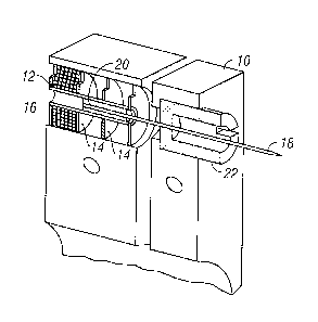
step glucose diagnostic system, and its method of manufacture, for one step
glucose
measurement that has structures for allowing a lancing event to be conducted,
collecting
a sample, transporting a sample and measuring the sample.
[0010] Another object of the present invention is to provide a fully
integrated, one
step glucose diagnostic system, and its method of manufacture, for one step
glucose
measurement that has structures for allowing a lancing event to be conducted,
collecting
a sample, transporting a sample and measuring the sample, where the structures
are
closely fluidicly coupled, such that a sample, expressed from a lancing event,
presents
itself at a prescribed location, and the structures enable the collection of
this sample and
it is subsequently transported to the measurement cell.
[0011] Yet another object of the present invention is to provide a
glucose diagnostic
system, and its method of manufacture, with a glucose sensor with structures
that
enables a lancing event, accomplish the sample capture and sample transport
functions
in a sensor design in one step testing.
[0012] Still another object of the present invention is to provide a
glucose diagnostic
system, and its method of manufacture, where a capillary flow is provided for
blood to
travel directly from a wound to the sensor port on a housing, and thus the
volume of
blood produced at the wound site, regardless of its droplet geometry, is
completely
transported to the analyte detecting member.
[0013] These and other objects of the present invention are achieved in a
test strip
device that has a first substrate with a first electrode and a second
substrate with a
second electrode. The second substrate includes a fluid passage way between
the first
and second substrates. A spacer layer includes an aperture coupled to the
fluid
2
CA 02832495 2013-10-04
WO 2012/142571 PCT/US2012/033768
passage way and positioned between the first and second electrodes. A reaction
zone/sensor is formed between the first and second electrodes. A hydrophilic
sample
collection structure is provided.
[0014] In another embodiment, a test strip device for testing a biologic
analyte
obtained by lancing a finger includes an aperture in the test strip providing
a path for a
penetrating member. A sample-capture feature and a sample-collection feature
are
provided. A transport pathway moves the analyte to a specified portion of the
test strip
for reaction with a reagent and measurement of the reaction products.
[0015] In another embodiment, a test strip device has an aperture in a
test strip that
provides a path for a penetrating member. A sample-capture feature and a
sample-
collection feature are included. A transport pathway is created by covering
the substrate
of the test strip with a cover layer which provides a two-dimensional
capillary area over
which the analyte spreads automatically by means of capillary forces and in
which
reagent exists within said capillary area which reacts with the analyte such
that the
optical properties of the two-dimensional capillary area are changed in
proportion to the
concentration of the analyte and measurement of said concentration is by
optical
reflectance, transmission, or fluorescence.
[0016] In anther embodiment, a test strip device includes an aperture in
the test strip
to provid a path for a penetrating member. Sample-capture and sample-
collection
features are included in which the sample-collection feature is at least one
of, a micro-
fluidic hydrophilic structure containing reagent which reacts with an analyte.
BRIEF DESCRIPTION OF THE DRAWINGS
[0017] Figure 1 illustrates an embodiment of a controllable force driver
in the form of
a cylindrical electric penetrating member driver using a coiled solenoid-type
configuration.
[0018] Figure 2A illustrates a displacement over time profile of a
penetrating
member driven by a harmonic spring/mass system.
[0019] Figure 2B illustrates the velocity over time profile of a
penetrating member
driver by a harmonic spring/mass system.
[0020] Figure 20 illustrates a displacement over time profile of an
embodiment of a
controllable force driver.
[0021] Figure 2D illustrates a velocity over time profile of an
embodiment of a
controllable force driver.
[0022] Figure 3 is a diagrammatic view illustrating a controlled feed-
back loop.
3
CA 02832495 2013-10-04
WO 2012/142571 PCT/US2012/033768
[0023] Figure 4 is a perspective view of a tissue penetration device
having features
of the invention.
[0024] Figure 5 is an elevation view in partial longitudinal section of
the tissue
penetration device of Figure 4.
[0025] Figure 6A shows one embodiment of a device which may use the
present
invention.
[0026] Figure 6B shows one embodiment of a cartridge according to the
present
invention.
[0027] Figure 7 is a perspective view of one embodiment with mesh on a
cartridge.
[0028] Figure 8 is a view showing a penetrating member diameter.
[0029] Figure 9 shows one embodiment of the invention with a mesh with an
opening for penetrating member exit.
[0030] Figures 10 A through 10C show various embodiments of sample
capture
devices.
[0031] Figure 11 is a side view of a sample capture device.
[0032] Figures 12A through 12D show various embodiments of sample capture
devices.
[0033] Figure 13 shows one method of manufacturing a sample capture
device.
[0034] Figures 14 through 16 show other configurations of a device
according to the
present invention.
[0035] Figure 17 shows one method of manufacturing a sample capture
device.
[0036] Figure 18 through 21 show configurations of sample capture
devices.
[0037] Figures 22(a) and 22(b), an analyte diagnostic system is provided
that uses
one or more test strips with sample capture
[0038] Figures 23 and 24 are exploded views of a test strip of Figures
22(a) and
22(b).
[0039] Figure 25 illustrates one embodiment of a test strip with sample
capture
positioned adjacent to a sensor/reaction zone, but does not impinge on the
sensor/reaction zone, to provide a close fluidic coupling.
[0040] Figure 26 illustrates an embodiment of a strip with a penetrating
member axis
that is perpendicular to a plane of the test strip.
[0041] Figures 26(a) through 26(j) illustrates various process flow steps
in creating
the Figure 26 embodiment.
[0042] Figure 27 illustrates another embodiment of a strip with sample
capture for a
one step bleed to read.
[0043] Figures 27(a) through 27(i) illustrates various process flow steps
in creating
the Figure 27 embodiment.
4
CA 02832495 2013-10-04
WO 2012/142571 PCT/US2012/033768
[0044] Figure 28 illustrates an embodiment of a strip with sample capture
provided
through a top of a sensor/reaction zone.
[0045] Figures 28(a) through 28(j) illustrates various process flow steps
in creating
the Figure 28 embodiment.
[0046] Figure 29 illustrates an embodiment of a strip with sample capture
that has a
lancing aperture in a substrate for a needle to pass through.
[0047] Figures 29(a) through 29(h) illustrates various process flow steps
in creating
the Figure 29 embodiment.
[0048] Figure 30 illustrates an embodiment of a strip with sample capture
placed on
the edge of the sensor/reaction zone channel, and impinges into the
sensor/reaction
zone.
[0049] Figures 30(a) through 30(h) illustrates various process flow steps
in creating
the Figure 30 embodiment.
[0050] Figure 31 illustrates an embodiment of a strip with a sample
capture structure
orthogonal to a plane of the strip.
[0051] Figures 31(a) through 31(l) illustrates various process flow steps
in creating
the Figure 31 embodiment.
[0052] Figure 32 illustrates an embodiment of the test strip that
integrates the
following structure and capabilities in an effective way to, (i) generate a
sample is
through using a controlled lancing event, where the profile of the lancing
event is
controlled; (ii) collect a blood sample and have the lancing event occur such
that a
lancing needle path is perpendicular to the plane of a circular sample
collection
structure; and (iii) transport the sample, once collected, through a
hydrophilic treated
capillary connecting the sample collection to the sensor.
[0053] Figure 33 illustrates different sensors of the Figure 32
embodiment.
[0054] Figures 33(a) through 33( f) illustrates an embodiment of process
flow steps
for manufacture of the Figure 32 and 33 strip.
[0055] Figures 34 through 36 are views of the strip 600.
DESCRIPTION OF THE SPECIFIC EMBODIMENTS
[0056] It is to be understood that both the foregoing general description
and the
following detailed description are exemplary and explanatory only and are not
restrictive
of the invention, as claimed. It may be noted that, as used in the
specification and the
appended claims, the singular forms "a", "an" and "the" include plural
referents unless
the context clearly dictates otherwise. Thus, for example, reference to "a
material" may
include mixture's of materials, reference to "a chamber" may include multiple
chambers,
and the like. References cited herein are hereby incorporated by reference in
their
CA 02832495 2013-10-04
WO 2012/142571 PCT/US2012/033768
entirety, except to the extent that they conflict with teachings explicitly
set forth in this
specification.
[0057] In this specification and in the claims which follow, reference
will be made to
a number of terms which shall be defined to have the following meanings:
"Optional" or"
optionally" means that the subsequently described circumstance may or may not
occur,
so that the description includes instances where the circumstance occurs and
instances
where it does not. For example, if a device optionally contains a feature for
analyzing a
blood sample, this means that the analysis feature may or may not be present,
and,
thus, the description includes structures wherein a device possesses the
analysis
feature and structures wherein the analysis feature is not present.
[0058] Figures 34 through 36 illustrate an embodiment of a strip of the
present
invention with, (i) a penetrating member path through the strip; (ii) sample
capture
feature with cover that has hole larger than the micro sponge with a
hydrophobic on the
upper surface; (iii) and a sample collection feature, where the hydrophilic
micro sponge
can surround the penetrating member and exposed to the skin on a finger when
in close
proximity; and spacer forms the walls of the sample transport feature.
[0059] The present invention may be used with a variety of different
penetrating
member drivers. It is contemplated that these penetrating member drivers may
be spring
based, solenoid based, magnetic driver based, nanornuscle based, or based on
any
other mechanism useful in moving a penetrating member along a path into
tissue. It
should be noted that the present invention is not limited by the type of
driver used with
the penetrating member feed mechanism. One suitable penetrating member driver
for
use with the present invention is shown in Figure 1.
[0060] This is an embodiment of a solenoid type electromagnetic driver
that is
capable of driving an iron core or slug mounted to the penetrating member
assembly
using a direct current (DC) power supply. The electromagnetic driver includes
a driver
coil pack that is divided into three separate coils along the path of the
penetrating
member, two end coils and a middle coil. Direct current is alternated to the
coils to
advance and retract the penetrating member. Although the driver coil pack is
shown with
three coils, any suitable number of coils may be used, for example, 4,5, 6,7
or more
coils may be used.
[0061] Referring to the embodiment of Figure 1, the stationary iron
housing 10 may
contain the driver coil pack with a first coil 12 flanked by iron spacers 14
which
concentrate the magnetic flux at the inner diameter creating magnetic poles.
The inner
insulating housing 16 isolates the penetrating member 18 and iron core 20 from
the coils
and provides a smooth, low friction guide surface. The penetrating member
guide 22
further centers the penetrating member 18 and iron core 20. The penetrating
member 18
6
CA 02832495 2013-10-04
WO 2012/142571 PCT/US2012/033768
is protracted and retracted by alternating the current between the first coil
12, the middle
coil, and the third coil to attract the iron core 20. Reversing the coil
sequence and
attracting the core and penetrating member back into the housing retracts the
penetrating member. The penetrating member guide 22 also serves as a stop for
the
iron core 20 mounted to the penetrating member 18.
[0062] As discussed above, tissue penetration devices which employ spring
or cam
driving methods have a symmetrical or nearly symmetrical actuation
displacement and
velocity profiles on the advancement and retraction of the penetrating member
as shown
in Figures 2 and 3. In most of the available penetrating member devices, once
the
launch is initiated, the stored energy determines the velocity profile until
the energy is
dissipated.
[0063] Controlling impact, retraction velocity, and dwell time of the
penetrating
member within the tissue can be useful in order to achieve a high success rate
while
accommodating variations in skin properties and minimize pain. Advantages can
be
achieved by taking into account of the fact that tissue dwell time is related
to the amount
of skin deformation as the penetrating member tries to puncture the surface of
the skin
and variance in skin deformation from patient to patient based on skin
hydration.
[0064] In this embodiment, the ability to control velocity and depth of
penetration
may be achieved by use of a controllable force driver where feedback is an
integral part
of driver control. Such drivers can control either metal or polymeric
penetrating members
or any other type of tissue penetration element. The dynamic control of such a
driver is
illustrated in Figure. 2C which illustrates an embodiment of a controlled
displacement
profile and Figure 2D which illustrates an embodiment of a the controlled
velocity profile.
These are compared to Figures 2A and 2B, which illustrate embodiments of
displacement and velocity profiles, respectively, of a harmonic spring/mass
powered
driver. Reduced pain can be achieved by using impact velocities of greater
than about 2
m/s entry of a tissue penetrating element, such as a penetrating member, into
tissue.
[0065] Other suitable embodiments of the penetrating member driver are
described
in commonly assigned, copending U. S. Patent Application Ser. No. 10/127,395,
(Attorney Docket No. 38187-2551) filed April 19,2002 and previously
incorporated
herein.
[0066] Figure 3 illustrates the operation of a feedback loop using a
processor 60.
The processor 60 stores profiles 62 in non-volatile memory. A user inputs
information 64
about the desired circumstances or parameters for a lancing event. The
processor 60
selects a driver profile 62 from a set of alternative driver profiles that
have been
preprogrammed in the processor 60 based on typical or desired tissue
penetration
device performance determined through testing at the factory or as programmed
in by
7
CA 02832495 2013-10-04
WO 2012/142571 PCT/US2012/033768
the operator. The processor 60 may customize by either scaling or modifying
the profile
based on additional user input information 64. Once the processor has chosen
and
customized the profile, the processor 60 is ready to modulate the power from
the power
supply 66 to the penetrating member driver 68 through an amplifier 70. The
processor
60 may measure the location of the penetrating member 72 using a position
sensing
mechanism 74 through an analog to digital converter 76 linear encoder or other
such
transducer. Examples of position sensing mechanisms have been described in the
embodiments above and may be found in the specification for commonly assigned,
copending U.S. Patent Application Ser. No. 10/127,395, (Attorney Docket No.
38187-
2551) filed April 19,2002 and previously incorporated herein. The processor 60
calculates the movement of the penetrating member by comparing the actual
profile of
the penetrating member to the predetermined profile. The processor 60
modulates the
power to the penetrating member driver 68 through a signal generator 78, which
may
control the amplifier 70 so that the actual velocity profile of the
penetrating member does
not exceed the predetermined profile by more than a preset error limit. The
error limit is
the accuracy in the control of the penetrating member.
[0067] After the lancing event, the processor 60 can allow the user to
rank the
results of the lancing event. The processor 60 stores these results and
constructs a
database 80 for the individual user. Using the database 79, the processor 60
calculates
the profile traits such as degree of painlessness, success rate, and blood
volume for
various profiles 62 depending on user input information 64 to optimize the
profile to the
individual user for subsequent lancing cycles. These profile traits depend on
the
characteristic phases of penetrating member advancement and retraction. The
processor 60 uses these calculations to optimize profiles 62 for each user. In
addition to
user input information 64, an internal clock allows storage in the database 79
of
information such as the time of day to generate a time stamp for the lancing
event and
the time between lancing events to anticipate the user's diurnal needs. The
database
stores information and statistics for each user and each profile that
particular user uses.
[0068] In addition to varying the profiles, the processor 60 can be used
to calculate
the appropriate penetrating member diameter and geometry suitable to realize
the blood
volume required by the user. For example, if the user requires about 1-5
microliter
volume of blood, the processor 60 may select a 200 micron diameter penetrating
member to achieve these results. For each class of penetrating member, both
diameter
and penetrating member tip geometry, is stored in the processor 60 to
correspond with
upper and lower limits of attainable blood volume based on the predetermined
displacement and velocity profiles.
8
CA 02832495 2013-10-04
WO 2012/142571 PCT/US2012/033768
[0069] The lancing device is capable of prompting the user for
information at the
beginning and the end of the lancing event to more adequately suit the user.
The goal is
to either change to a different profile or modify an existing profile. Once
the profile is set,
the force driving the penetrating member is varied during advancement and
retraction to
follow the profile. The method of lancing using the lancing device comprises
selecting a
profile, lancing according to the selected profile, determining lancing
profile traits for
each characteristic phase of the lancing cycle, and optimizing profile traits
for
subsequent lancing events.
[0070] Figure 4 illustrates an embodiment of a tissue penetration device,
more
specifically, a lancing device 80 that includes a controllable driver 179
coupled to a
tissue penetration element. The lancing device 80 has a proximal end 81 and a
distal
end 82. At the distal end 82 is the tissue penetration element in the form of
a penetrating
member 83, which is coupled to an elongate coupler shaft 84 by a drive coupler
85. The
elongate coupler shaft 84 has a proximal end 86 and a distal end 87. A driver
coil pack
88 is disposed about the elongate coupler shaft 84 proximal of the penetrating
member
83. A position sensor 91 is disposed about a proximal portion 92 of the
elongate coupler
shaft 84 and an electrical conductor 94 electrically couples a processor 93 to
the
position sensor 91. The elongate coupler shaft 84 driven by the driver coil
pack 88
controlled by the position sensor 91 and processor 93 form the controllable
driver,
specifically, a controllable electromagnetic driver.
[0071] Referring to Figure 5, the lancing device 80 can be seen in more
detail, in
partial longitudinal section. The penetrating member 83 has a proximal end 95
and a
distal end 96 with a sharpened point at the distal end 96 of the penetrating
member 83
and a drive head 98 disposed at the proximal end 95 of the penetrating member
83. A
penetrating member shaft 201 is disposed between the drive head 98 and the
sharpened point 97. The penetrating member shaft 201 may be comprised of
stainless
steel, or any other suitable material or alloy and have a transverse dimension
of about
0.1 to about 0.4 mm. The penetrating member shaft may have a length of about 3
mm to
about 50 mm, specifically, about 15 mm to about 20 mm. The drive head 98 of
the
penetrating member 83 is an enlarged portion having a transverse dimension
greater
than a transverse dimension of the penetrating member shaft 201 distal of the
drive
head 98. This configuration allows the drive head 98 to be mechanically
captured by the
drive coupler 85. The drive head 98 may have a transverse dimension of about
0.5 to
about 2 mm.
[0072] A magnetic member 102 is secured to the elongate coupler shaft 84
proximal
of the drive coupler 85 on a distal portion 203 of the elongate coupler shaft
84. The
magnetic member 102 is a substantially cylindrical piece of magnetic material
having an
9
CA 02832495 2013-10-04
WO 2012/142571 PCT/US2012/033768
axial lumen 204 extending the length of the magnetic member 102. The magnetic
member 102 has an outer transverse dimension that allows the magnetic member
102
to slide easily within an axial lumen 105 of a low friction, possibly
lubricious, polymer
guide tube 105'disposed within the driver coil pack 88. The magnetic member
102 may
have an outer transverse dimension of about 1.0 to about 5.0 mm, specifically,
about 2.3
to about 2.5 mm. The magnetic member 102 may have a length of about 3.0 to
about
5.0 mm, specifically, about 4.7 to about 4.9 mm. The magnetic member 102 can
be
made from a variety of magnetic materials including ferrous metals such as
ferrous
steel, iron, ferrite, or the like. The magnetic member 102 may be secured to
the distal
portion 203 of the elongate coupler shaft 84 by a variety of methods including
adhesive
or epoxy bonding, welding, crimping or any other suitable method.
[0073] Proximal of the magnetic member 102, an optical encoder flag 206
is
secured to the elongate coupler shaft 84. The optical encoder flag 206 is
configured to
move within a slot 107 in the position sensor 91. The slot 107 of the position
sensor 91
is formed between a first body portion 108 and a second body portion 109 of
the position
sensor 91.
[0074] The slot 107 may have separation width of about 1.5 to about 2.0
mm. The
optical encoder flag 206 can have a length of about 14 to about 18 mm, a width
of about
3 to about 5 mm and a thickness of about 0.04 to about 0.06 mm.
[0075] The optical encoder flag 206 interacts with various optical beams
generated
by LEDs disposed on or in the position sensor body portions 108 and 109 in a
predetermined manner. The interaction of the optical beams generated by the
LEDs of
the position sensor 91 generates a signal that indicates the longitudinal
position of the
optical flag 206 relative to the position sensor 91 with a substantially high
degree of
resolution. The resolution of the position sensor 91 may be about 200 to about
400
cycles per inch, specifically, about 350 to about 370 cycles per inch. The
position sensor
91 may have a speed response time (position/time resolution) of 0 to about
120,000 Hz,
where one dark and light stripe of the flag constitutes one Hertz, or cycle
per second.
The position of the optical encoder flag 206 relative to the magnetic member
102, driver
coil pack 88 and position sensor 91 is such that the optical encoder 91 can
provide
precise positional information about the penetrating member 83 over the entire
length of
the penetrating member's power stroke.
[0076] An optical encoder that is suitable for the position sensor 91 is
a linear optical
incremental encoder, model HEDS 9200, manufactured by Agilent Technologies.
The
model HEDS 9200 may have a length of about 20 to about 30 mm, a width of about
8 to
about 12 mm, and a height of about 9 to about 11 mm. Although the position
sensor 91
illustrated is a linear optical incremental encoder, other suitable position
sensor
CA 02832495 2013-10-04
WO 2012/142571 PCT/US2012/033768
embodiments could be used, provided they posses the requisite positional
resolution
and time response. The HEDS 9200 is a two channel device where the channels
are 90
degrees out of phase with each other. This results in a resolution of four
times the basic
cycle of the flag. These quadrature outputs make it possible for the processor
to
determine the direction of penetrating member travel. Other suitable position
sensors
include capacitive encoders, analog reflective sensors, such as the reflective
position
sensor discussed above, and the like.
[0077] A coupler shaft guide 111 is disposed towards the proximal end 81
of the
lancing device 80. The guide 111 has a guide lumen 112 disposed in the guide
111 to
slidingly accept the proximal portion 92 of the elongate coupler shaft 84. The
guide 111
keeps the elongate coupler shaft 84 centered horizontally and vertically in
the slot 102 of
the optical encoder 91.
[0078] The driver coil pack 88, position sensor 91 and coupler shaft
guide 111 are
all secured to a base 113. The base 113 is longitudinally coextensive with the
driver coil
pack 88, position sensor 91 and coupler shaft guide 111. The base 113 can take
the
form of a rectangular piece of metal or polymer, or may be a more elaborate
housing
with recesses, which are configured to accept the various components of the
lancing
device 80.
[0079] As discussed above, the magnetic member 102 is configured to slide
within
an axial lumen 105 of the driver coil pack 88. The driver coil pack 88
includes a most
distal first coil 114, a second coil 115, which is axially disposed between
the first coil 114
and a third coil 116, and a proximal-nnost fourth coil 117. Each of the first
coil 114,
second coil 115, third coil 116 and fourth coil 117 has an axial lumen. The
axial lumens
of the first through fourth coils are configured to be coaxial with the axial
lumens of the
other coils and together form the axial lumen 105 of the driver coil pack 88
as a whole.
Axially adjacent each of the coils 114-117 is a magnetic disc or washer 118
that
augments completion of the magnetic circuit of the coils 114-117 during a
lancing cycle
of the device 80. The magnetic washers 118 of the embodiment of Figure 5 are
made of
ferrous steel but could be made of any other suitable magnetic material, such
as iron or
ferrite.
[0080] The outer shell 89 of the driver coil pack 88 is also made of iron
or steel to
complete the magnetic path around the coils and between the washers 118. The
magnetic washers 118 have an outer diameter commensurate with an outer
diameter of
the driver coil pack 88 of about 4.0 to about 8. 0 mm. The magnetic washers
118 have
an axial thickness of about 0.05, to about 0.4 mm, specifically, about 0.15 to
about 0.25
mm.
11
CA 02832495 2013-10-04
WO 2012/142571 PCT/US2012/033768
[0081] Wrapping or winding an elongate electrical conductor 121 about an
axial
lumen until a sufficient number of windings have been achieved forms the coils
114-117.
The elongate electrical conductor 121 is generally an insulated solid copper
wire with a
small outer transverse dimension of about 0.06 mm to about 0.88 mm,
specifically,
about 0.3 mm to about 0.5 mm. In one embodiment, 32 gauge copper wire is used
for
the coils 114-117. The number of windings for each of the coils 114-117 of the
driver
pack 88 may vary with the size of the coil, but for some embodiments each coil
114-117
may have about 30 to about 80 turns, specifically, about 50 to about 60 turns.
Each coil
114-117 can have an axial length of about 1.0 to about 3.0 mm, specifically,
about 1.8 to
about 2.0 mm. Each coil 114-117 can have an outer transverse dimension or
diameter
of about 4.0, to about 2.0 mm, specifically, about 9.0 to about 12.0 mm. The
axial lumen
105 can have a transverse dimension of about 1.0 to about 3.0 mm.
[0082] It may be advantageous in some driver coil 88 embodiments to
replace one
or more of the coils with permanent magnets, which produce a magnetic field
similar to
that of the coils when the coils are activated. In particular, it may be
desirable in some
embodiments to replace the second coil 115, the third coil 116 or both with
permanent
magnets. In addition, it may be advantageous to position a permanent magnet at
or near
the proximal end of the coil driver pack in order to provide fixed magnet
zeroing function
for the magnetic member (Adams magnetic Products 23A0002 flexible magnet
material
(800) 747-7543).
[0083] Referring now to Figures 6A and 6B, yet another embodiment of the
present
invention will now be described. It should be understood that this embodiment
may be
adapted for use with devices described in commonly assigned copending U. S.
Patent
Applications Ser. No. 10/323,624 (Attorney Docket No. 38187-2608) filed
December 18,
2002. Figure 6A shows a device that may optionally use a cartridge as shown in
Figure
6B. Figure 6B shows a radial cartridge 220. The cartridge 220 may optionally
include a
sterility barrier 232 and a substrate 250 having a plurality of analyte
detecting members
226. In this embodiment, the cartridge 220 is designed so that blood will
enter the fluid
chamber 228 and be held there for analysis.
[0084] Figure 6B shows the radial cartridge 220 may optionally be used
with a
lancing device 230. The radial cartridge 220 may optionally be sealed with a
sterility
barrier 232 and be coupled to analyte detecting members mounted on a substrate
234.
A suitable device is described in commonly assigned, copending U. S. Patent
Application No. 10/429,196 (Attorney Docket No. 38187-2662) fully incorporated
herein
by reference for all purposes.
[0085] It should be understood that in some embodiments, the layer 234
may be
removed and the bottom layer of the cartridge 220 sealed. Instead, a ring 252
with a
12
CA 02832495 2013-10-04
WO 2012/142571 PCT/US2012/033768
plurality of analyte detecting members 254 (such as those shown in Figures 10A-
20)
may optionally be in a ring configuration around the penetrating member
cartridge 220.
This orients one analyte detecting member 254 for each penetrating member in
cartridge 220. Some embodiments may optionally have portions of the ring 254
fold
underneath the cartridge 220 as shown in Figures 14 and 15.
[0086] Referring now to Figure 7, as described above, when a penetrating
member
340 is actuated and extends outward from the cartridge 220, the mesh 320 may
optionally be pushed aside or pierced by the exiting member 340. The resulting
ring of
capillary fibers 342 around the wound channel would be available after the
penetrating
member was retracted to wick the blood sample into the sample channel.
[0087] The physical characteristics of the mesh 320 is one aspect for
successfully
transport of blood to the analyte detecting member 250. In one embodiment, the
mesh
320 may be pliable enough the allow relaxation, but maintain contact or near-
contact
with the skin surface. An active region could be striped on the mesh to allow
the blood to
only travel in the direction towards the analyte detecting member. A different
gauge
capillary fiber may optionally be used on the mains versus the cross. In
another
embodiment, the mains may optionally have a smaller gage and higher pitch to
promote
vertical movement. As an additional benefit, if the mesh assisted in
distributing the force
of penetrating member impact with the skin, the cutting efficiency of the
penetrating
member could be increased.
[0088] In another embodiment, the mesh 320 would reduce the amount of
micro
positioning used to assure that the droplet of body fluid gets to the analyte
detecting
member. The potential volume required by the analyte detecting member could be
reduced by reducing the amount of blood or body fluid that spontaneously rises
to the
surface of the skin that is either not removed from the skin once the surface
tension is
released in a traditional, nnicrofluidics methods. Traditional nnicrofluidics
could also have
a higher volume required to get the blood to the sample chamber.
[0089] Referring now to Figure 8, this embodiment of the present
invention pertains
to the 100 percent capture of a bodily fluid generated from a wound upon
lancing. There
are problems when the blood droplet formed immediately after lancing. The
droplet can
be positioned in any position 360 degrees along the circumference of the
lancing
location.
[0090] Due to the observed low jitter or lateral movement of the
penetrating member
during the lancing protocol, the fluidic sample capture aperture with mesh
will not
obstruct the path of the penetrating member. The model of the penetrating
member and
subsequent droplet formation has provided a geometric dimension that will
allow the
13
CA 02832495 2013-10-04
WO 2012/142571 PCT/US2012/033768
fluidic sample capture and transport structure to be constructed
circumnavigating the
entire penetrating member.
[0091] This penetrating member circumnavigating sample and capture mesh
structure will allow the capture of a produced droplet and transport it
directly to the
sensor measurement devices.
[0092] As seen in Figure 8, the drawing shows a calculation of the
aperture opening
based upon the penetrating member 340 diameter and both the observed and
specified
penetrating member lateral motion resolution. In addition, the aperture ring
contains a
collection of fluid channels, with respect to this particular disclosure, the
mesh is to
transport the captured bodily fluid to-the measurement sensors which also
circumnavigate the aperture opening.
[0093] This embodiment of the invention provides a sample, capture, and
transport
solution to that of an integrated physiological measurement device, which
allows the
capture of the fluidic sample by mesh immediately upon the penetrating member
operation. As seen in Figure 9, the structure contains an aperture ring
structure 360,
which surrounds or circumnavigates the penetrating member wound. Upon the
release
of the bodily fluid from the penetrating member wound, the bodily fluid
droplet grows
until comes in contact with a portion of the fluid transporting mesh 360. Upon
contact
with the fluid mesh, the bodily fluid through capillary action is wicked into
the capillary
mesh and brought forth to the sensors also contained in the aperture ring
structure. In
one embodiment, the mesh 360 takes the blood and distributes it over a uniform
surface.
[0094] There is insignificant amount of sucking, pumping, or capillary
force. In one
embodiment, the mesh 360 spread the blood until the fluid contacts a capillary
channel
and at that point, the pulling an sucking begins. This is step one spreading.
Step two is a
partial capillary or some pumping or sucking action (this is the pumping
action since
there are side walls that are now pulling). Step 3 is taking through a 90
degree bend to
bring the fluid to the analyte detecting member.
[0095] Figure 10A shows a close up of a portion of the mesh. Figure 10B
shows that
grooves or gratings 362 may also be used to serve the spreading function
described.
Such grooves may optionally be pressed and create striations on a plastic
surface. It is
creating a fine textured surface to distribute fluid. Figure 1 OC shows the
scoring or
grooves used to spread the materials.
[0096] The mesh 360 or the gratings serves as the initial capture up
front, which
direct blood to a capillary channel. It is also desirable in some embodiments
to transport
the blood quickly, hence it is desirable to engage the blood in whatever
orientation it
may be coming off of the penetrating member. Mesh also displaces volume and
thus it
14
CA 02832495 2013-10-04
WO 2012/142571 PCT/US2012/033768
will use a lower volume of blood during transport. Single and double meshes
can be
used. In the present invention, since this is an integrated device, the user
is blind as to
where the blood droplet is on the penetrating member. It can be in a variety
of
orientations and the present mesh 360 that surrounds the exit port will
capture the blood
and lead it to transport.
[0097] Regardless of where the blood droplet is, it will be transported.
In one
embodiment, it takes less than 10 seconds to transport blood to the analyte
detecting
member. In one embodiment, it takes less than 5 seconds to transport blood to
the
analyte detecting member.
[0098] Figure 11 shows that the blood coming out will contact a mesh 360,
regardless of the orientation of the blood on the penetrating member. This
surrounding
mesh helps to ensure capture. Referring now to Figures 12A-12C, the drawings
shown
describe several configurations, of which there are three, built and tested.
The structure
in Figure 12A is one embodiment with a cross section of a fluidic structure
380 with a
channel totally free of adhesives. The topside connecting sections comprise of
a PET
film hydrophobic on the outer most layer 382 and hydrophilic on the inner
layer 384
abutting against the hydrophobic double-sided adhesive layer 386. The bottom
side
would comprise of a PET film hydrophilic on the inner layer abutting against
the
hydrophobic adhesive and hydrophobic on the outside. The inner fluidic channel
region
would be a sandwich structure of top PET film/fluidic mesh structures/and
bottom PET
film. The PET surfaces abutting the mesh structures would be hydrophilic.
[0099] The structure in Figure 12B is a cross section of a fluidic
structure with a
channel free of adhesives. The structure 390 is very similar to the structure
previously
described.
[0100] However, the difference is in the surface energy of the top and
bottom PET
films. The hydrophobic surface 392 and hydrophilic surfaces 394 are reversed
such that
the outer surface is hydrophilic and the inner surface abutting either the
adhesive layer
or mesh is hydrophobic. The fluidic channel regions remain free of adhesive.
[0101] The structure in Figure 120 is a cross section of a fluidic
structure with a
channel totally free of adhesives. The structure is very similar to the first
structure
previously described. However, this structure also incorporates a fluid entry
port 396 of
which the surface directly facing the droplet of fluid has been slightly
oversized in order
to expose additional mesh material. There exist a smaller hole on one PET film
surface
which matches the hole size of the mesh and a larger dissimilar hole on the
opposite
sandwiching PET film surface.
[0102] Figure 12D shows a front view of the embodiment of Figure 120. The
blood
will be spread and then pulled in the direction indicating by arrows 400. Some
CA 02832495 2013-10-04
WO 2012/142571 PCT/US2012/033768
embodiments may optionally have a tapered configuration (shown by phantom line
402)
and facilitates flow around a 90 degree bend. The taper accounts for bulging
or bunch of
materials when the neck is bent, which narrows the effective channel available
for fluid
flow.
[0103] These embodiments of this invention entail a method of improving
fluidic flow
through fluidic mesh transport structures by moderating the selection of
hydrophobicity
or hydrophilicity through surface energy. This method of moderating or
modifying
surface energies can be done through a number of different means known to
those
practicing the arts.
[0104] There are a number of options that can be used to treat surfaces
to obtain a
particular surface preference for degree of hydrophilic or hydrophobic. The
concerns
relating to the selection of the preferred method of treating a surface
depends upon the
window of need for this respective treatment. If the window of preference were
for a
reliable long-term state, then the method may dictate that the bulk properties
of the
structured material or a physical coating that has good longevity be selected.
If the
window of preference were to be a short-term state, such as that used in the
application
of an adhesive, then the method of only treating the surface will be
preferred.
[0105] The metrology for determining the state of the surface is usually
the
measurement of the contact angle of a small liquid standard and the material
relative to
ambient air. The measurement and monitoring of this contact angle and surface
energy
of time is critical in determining the relative effectiveness of the surface
state treatment
or bulk fabrication.
[0106] The methods of treatment are but are not limited to: a). The
fabrication with a
natural bulk material used to determine the material's bulk surface properties
and the
entire process used to fabricate the material. An example of this would be the
treatment
of PET (Poly (ethylene terephthalate)) or raw polyester. b). The design of the
material's
surface texture pattern by fabrication processes in conjunction with the
material's natural
bulk properties. Physical molding or mechanical machining processes may
accomplish
this. An example of this would be the modification of Young's equation
presented later in
this discussion. c). The use of high energy sources such plasmas, ion guns,
and
sputtering techniques to either texture or modify the surface molecular
structure. This
would include vacuum ion milling, vacuum or argon plasmas, or atmospheric
plasmas or
corona processes. An example of this would be Argon plasma, Oxygen plasma, ion
milling, or Tantec corona treatments. d). The use of wet chemicals to etch and
texture
the surface molecular structure.
[0107] An example of this would be Tetra-Etch. e). The use of thin
polymer films
deposited by physical vacuum methodologies, spin on coatings, vapor deposited
16
CA 02832495 2013-10-04
WO 2012/142571 PCT/US2012/033768
methods, or wet deposited then activated via photonic treatments to actively
link
molecules of choice for the surface. An example of this would be films by
Surmodics. f).
The use by design and selection of membrane structures that require the insert
or
adhesion of films on to surfaces as to create the actual fluid conduction
path. An
example of this would be membrane films offered by Millipore or paper films
offered by
Scheicher & Schuell or Sefar America.
[0108] A Brief Discussion On Surface Energy of Polymers Wettability and
repellency
of polymers against water are basic surface properties of the polymers.
Hydrophillic and
hydrophobic sirfaces are results of interactions at an interface between
polymer and
water layers and closely related to the surface energy of the polymers.
Hydrophilic
surface means strong interactions with water, and polar groups have to exist
at the
surface of the polymer. As a result, the contact angle of the polymer against
water is
small. If the surface energy of the polymer is more than that of water (72.8
mJ/N), the
surface of the polymer will contact immediately with water, and the contact
angle will be
zero. A hydrophobic surface means weak interactions with water at an
interface, and the
surface consists mainly of non-polar groups. The contact angle of the polymer
against
water is as large as 90 degrees, in some cases more than 100 degrees.
[0109] The surface energy of a material is the excess energy per unit
area due to
the existence of the free surface. In liquids, the surface energy is
conventionally called
surface tension. When two different surfaces contact each other and the two
surfaces
are not mixed, the contact produces an interface and the excess energy is
generated at
the interface by the formation of the interface. The excess energy per unit
area is called
interfacial energy or interfacial tension. The contact angle of the polymer
against water
is a balance among the surface energy of the polymer (Ys) and of water (YI)
and the
interfacial energy (Ysl).
[0110] The balance of the equation is written YI COS theta = Ys-Ysl
Therefore, the
higher the surface energy of the polymer is and the lower the interfacial
energy is, the
lower the contact angle is. In the extreme case that Ys is equal to YI and Ysl
is zero, the
contact angle becomes zero, and complete wetting is accomplished.
[0111] The surface energy of the polymer defined by the excess energy per
unit
area due to the existence of the free surface is closely related to cohesive
energy
density of the polymer chains. Three methods are proposed for estimation of
the surface
energy of polymers: 1). The method from the contact angles of polymer against
different
liquids using Ys = YI (l+cos theta) ^2/ (4 phi"2) phi = (4 (VsVI) A (1/3))/ (
( (Vs" (1/3)) +
(VI" (1/3))) ^2 where Vs and VI are molar volumes of the polymer an dthe
liquid,
respectively.
17
CA 02832495 2013-10-04
WO 2012/142571 PCT/US2012/033768
[0112] 2). The method from the Zisman plat-theoretically, the estimated
value is not
the real surface energy value 3). The method from the surface tension of
melted
polymers.
[0113] The above discussions provide the basis and foundation of how
surface
energy on films and meshes can be both moderated and measured. The structures
in
this invention disclosure concern the creation of circular or rectangular
tubular structures
and how the fluidic flow might be moderated or enhanced by the use of surfaces
modified or moderated by the fore mentioned techniques. The three structures
were
fabricated and tested. However, the last structure or bottom structure
provided the best
wicking and attraction of fluid to the structure surface and transport into
the fluid
channel. The combination of the hydrophilic surfaces abutting the hydrophilic
mesh for
both sides of the fluidic channel and the dissimilar hole sizes exposing the
hydrophilic
mesh against a hydrophilic surface demonstrated excellent fluidic action.
Wicking action
upon the exposed hydrophilic mesh and combined hydrophilic surface and support
structure promoted immediate surface action. The combined hydrophilic channel
top and
bottom walls along with the capillary action of the hydrophilic mesh supported
immediate
fluid transport from source to destination.
[0114] Referring now to Figure 13, the drawings show a step by step
description of
the fabrication of one embodiment of an integrated mesh and adhesive
structure. The
layer by layer assembly is described in the drawings. Another figure at the
bottom shows
the final assembly of the structure. This invention pertains to the design and
fabrication
of mesh structures as a method of sample, capture, and transport of bodily
fluids. The
traditional methods of pattern definition in mesh membrane structures has been
to either
but and fit the mesh within a predefined physical capillary structure or the
impregnating
the mesh membrane pores by the process of screen printing.
[0115] The process of screen printing involves the use of many different
chemicals,
light energies, or vapors that might alter the chemistry of the mesh membrane
surface
chemistry or physics. Thus the use of a prefabricated, preformed, and
preprocessed
pressure sensitive adhesive to be pressed into the mesh might be the most
optimal
application for mesh membrane surfaces that are used in medical diagnostics.
[0116] Figure 13 shows one embodiment with a liners 420, an adhesive 422,
and
another liner 424. Mesh 426 is compressed into adhesive 428. A combination of
mesh
and adhesive is shown on top of liner. This embodiment of the invention
adheres to the
principal of using hydrophilic/hydrophobic surface tension. In some
embodiment, the
adhesives are used to define the channels. Both adhesives are hydrophobic to
minimize
delamination of the films. The adhesives may optionally be die cut to shape.
This
facilitates integration of manufacturing. The devices may optionally be hybrid
structures
18
CA 02832495 2013-10-04
WO 2012/142571 PCT/US2012/033768
using wicking material for capture and then a capillary structure for
transport. The mesh
leads a little into the capillary and then the fluid just flows. Figure 14
shows such a mesh
360 leading partially into a capillary structure 408. Figure 15 shows a side
view with the
electrodes 226 located over capillary structure 408. This an L-shaped
configuration.
[0117] Some embodiments may not have a L-bend and may be linear
configuration
that is vertical as indicated by phantom lines 440. Figure 15 also shows that
the wicking
member is oriented to be perpendicular to the path of the penetrating member
indicated
by arrow 361. The wicking member is oriented to intersect the path of the
penetrating
member indicated by arrow 361.
[0118] Referring now to Figure 16, the drawing shows a schematic top and
side
view depicting the integrated mesh membrane and capillary structure. This
embodiment
of the invention relates to the integration of a mesh membrane sample and
capture
structure with a capillary transport to insure stable glucometric measurement.
The
structure is useful to an integrated sample capture, transport, and
measurement device
for reliable and accurate performance with very small sample volumes.
[0119] This embodiment of the invention pertains to the design and
development of
a blood droplet sample capture, blood fluid transport, and delivery onto a
glucose
measurement device. The sample and capture mesh membrane mechanism guarantees
consistent capture of a droplet after a penetrating member procedure. The
resulting
blood droplet from the digit tip is captured by the mesh membrane structure
360 and
transported via the mesh membrane mechanism into a small capillary structure
408
consisting of the prior membrane structure less the mesh membrane onto the
surface of
the glucose measurement device. The height of this cavity for the measurement
structure is established by the electrochemistry limitations of the glucose
measurement
chemistry.
[0120] The height specified is known to those practicing the arts. This
structure will
allow certain sample capture, rapid transport, and reliable measurement. In an
electrochemical setup, the electrodes (either a 2 electrode setup or a 3
electrode setup)
will be positioned to sample body fluid in the capillary structure area 408.
[0121] Referring now to Figure 17, the drawing shows a step by step
description of
one embodiment for the fabrication of an integrated mesh and adhesive
structure. It
should be noted that the additional layer of a hydrophilic adhesive layer at
the bottom of
the mesh membrane provides an excellent sample capture surface within the
fluid
channel and at the same time augmenting the channel sealing and definition at
non
fluidic flow regions by design. Figure 17 shows a hydrophobic adhesive layer
450
between two liners. The device may also have a mesh layer 454. There may
optionally
19
CA 02832495 2013-10-04
WO 2012/142571 PCT/US2012/033768
be a hydrophilic adhesive layer 456. After assembly, the device will have
fluid channels
460 and non-channel regions 462.
[0122] This embodiment of the present invention relates to the
integration of
hydrophobic and hydrophilic adhesives onto and within a mesh membrane for the
enhancement of fluidic capture and transport flow. The developed surface
energy
properties of specific adhesive formulations has allowed the availability of
extreme
hydrophobic and hydrophilic properties and various viscosities as to promote
absorption
into the pores of the mesh membranes. Through proper mixing by design, the
masking
of mesh membranes has been obtainable with pressure sensitive adhesives along
with
fluid attractive properties to direct optimal fluid capture, transport, and
flow.
[0123] This embodiment of the present invention may also pertain to the
design and
fabrication of mesh structures as a method of sample, capture, and transport
of bodily
fluids. The traditional methods of pattern definition in mesh membrane
structures has
been to either but and fit the mesh within a predefined physical capillary
structure or the
impregnating the mesh membrane pores by the process of screen printing.
[0124] The process of screen printing involves the use of many different
chemicals,
light energies, or vapors that might alter the chemistry of the mesh membrane
surface
chemistry or physics. Thus the use of a prefabricated, preformed, and
preprocessed
pressure sensitive adhesive to be pressed into the mesh might be the most
optimal
application for mesh membrane surfaces that are used in medical diagnostics.
[0125] The uniqueness of this embodiment of the invention is the further
integration
of a selective layer of hydrophilic adhesive onto the mesh membrane fluid
channel
structure to serve a dual purpose of sealing the fluid channel structure from
lateral flow
leaks and at the same time serve as an enhancement surface for the fluid and
transport
channel structure.
[0126] Referring now to Figure 18 a still further embodiment of the
present invention
shows that the wicking material may optionally be designed to have flaps which
only
substantially surround the penetrating member exit but will still engage blood
or other
body fluid flowing from the wound. Other geometries are shown in Figures 19-
21.
[0127] Figure 19 shows one embodiment with four rectangular tabs 502.
Figure 20
shows an embodiment with four triangular tabs 504. Figure 21 shows an
embodiment
with three rectangular tabs 506. These tabs are positioned to contact body
fluid that may
be expressed from a wound on the patient. It should be understood that a
variety of
other shapes, combinations of shapes, combination of shapes described above,
and/or
other configurations may be used so long as the substantially ensure the blood
coming
from any orientation from the penetrating member wound will be captured. Some
embodiments may simply have a round opening without the tabs. Other shaped
CA 02832495 2013-10-04
WO 2012/142571 PCT/US2012/033768
openings such as square, rectangular, oval, triangular, octagonal, polygonal,
or
combinations of any of the above are possible.
[0128] While the invention has been described and illustrated with
reference to
certain particular embodiments thereof, those skilled in the art will
appreciate that
various adaptations, changes, modifications, substitutions, deletions, or
additions of
procedures and protocols may be made without departing from the spirit and
scope of
the invention.
[0129] For example, with any of the above embodiments, the location of
the
penetrating member drive device may be varied, relative to the penetrating
members or
the cartridge. With any of the above embodiments, the penetrating member tips
may be
uncovered during actuation (i. e. penetrating members do not pierce the
penetrating
member enclosure or protective foil during launch). With any of the above
embodiments,
the penetrating members may be a bare penetrating member during launch. With
any of
the above embodiments, the penetrating members may be bare penetrating members
prior to launch as this may allow for significantly tighter densities of
penetrating
members. In some embodiments, the penetrating members may be bent, curved,
textured, shaped, or otherwise treated at a proximal end or area to facilitate
handling by
an actuator. The penetrating member may be configured to have a notch or
groove to
facilitate coupling to a gripper. The notch or groove may be formed along an
elongate
portion of the penetrating member. With any of the above embodiments, the
cavity may
be on the bottom or the top of the cartridge, with the gripper on the other
side. In some
embodiments, analyte detecting members may be printed on the top, bottom, or
side of
the cavities. The front end of the cartridge maybe in contact with a user
during lancing.
The same driver may be used for advancing and retraction of the penetrating
member.
[0130] The penetrating member may have a diameters and length suitable
for
obtaining the blood volumes described herein. The penetrating member driver
may also
be in substantially the same plane as the cartridge. In some embodiments, one
pin may
be configured to contact more than one electrode (such as a U-shaped pin that
contacts
both the counter and reference electrodes). The driver may use a through hole
or other
opening to engage a proximal end of a penetrating member to actuate the
penetrating
member along a path into and out of the tissue. With any of the above
embodiments, the
strips may have rectangular configurations instead of the lollipop
configuration such as
that shown in Figure 12D. It should understood that any of the inventions
herein may be
used in conjunction or adapted for use with devices disclosed in U. S. Patent
Applications Attorney Docket No. 38187-2551, 38187-2608, and 38187-2662. This
includes but is not limited to integration of various wicking materials,
capillary structures,
combinations of the above, or the like with a radial cartridge as described in
38187-
21
CA 02832495 2013-10-04
WO 2012/142571 PCT/US2012/033768
2662. The present application is related to US Provisional Application Ser.
No.
60/533,981 (Attorney Docket no. 38187-2723).
[0131] In one embodiment of the present invention, illustrated in Figures
22(a) and
22(b), an analyte diagnostic system is provided that uses one or more test
strips 600.
Figures 23 and 24 are exploded views of a test strip 600. The analyte sensor
of the test
strip may have an electrochemical configuration, or a colorimetric or
photometric that is
an electrochemical test strip. In any embodiment, the test strip devices and
analyte
sensors are useful in the determination of a wide variety of different analyte
concentrations, where representative analytes include, but are not limited to,
glucose,
cholesterol, lactate, alcohol, and the like. In many embodiments, the subject
test strips
are used to determine the glucose concentration in a physiological sample,
e.g.,
interstitial fluid, blood, blood fractions, constituents thereof, and the
like.
[0132] The test strip 600 can be included in an analyte sensor defined by
an
electrochemical cell generally having two spaced-apart and opposing electrodes
694
and 696, respectively referred to herein as bottom electrode 694 and top
electrode 696,
though in use they may oriented in any direction. At least the surfaces of
electrodes 694
and 696 facing each other are comprised of a conductive layer 698 and 6100,
respectively, such as a metal, deposited on an inert substrate 6102 and 6104,
respectively. The spacing between the two electrodes is a result of the
presence of a
spacer layer 6106 positioned or sandwiched between electrodes 694 and 696. In
one
embodiment, a micro-sponge coating and a mask coating can be including
[0133] In various embodiments, the analyte sensor of the present
invention includes
a test strip 600 configured to provide, (i) the user with an ability to place
its can place its
finger on a housing that houses at least a portion of the test strip 600,
press a button
and obtain an accurate glucose reading; (ii) a one step glucose diagnostic
system is
provided that has a seamless, automatic series of steps to lance the user's
finger, draw
blood, capture and transport the blood to a sensor of the test strip 600 and
report a
result, (iii) one step glucose measurement using sample capture, sample
transport and
measurement with an electrochemical sensor; (iv) one step glucose measurement
that
has structures for allowing a lancing event to be conducted, collecting a
sample,
transporting a sample and measuring the sample; (v) a step glucose measurement
with
structures for allowing a lancing event to be conducted, collecting a sample,
transporting
a sample and measuring the sample, where the structures are closely fluidicly
coupled,
such that a sample, expressed from a lancing event, presents itself at a
prescribed
location, and the structures enable the collection of this sample and it is
subsequently
transported to the measurement cell; (vi) a glucose sensor with structures
that enables a
22
CA 02832495 2013-10-04
WO 2012/142571 PCT/US2012/033768
lancing event, accomplish the sample capture and sample transport functions in
a
sensor design in one step testing.
[0134] In one embodiment of the present invention, a one step analyte
diagnostic
system is provide that allows a user to place its finger on a housing of the
analyte
diagnostic system, activate such as by pressing a button and obtain an
accurate glucose
reading in one single action. This is called bleed to read without additional
actions. A
seamless, automatic series of steps is used to lance the finger, draw blood,
capture and
transport the blood to the glucose sensor and then report a result. In one
embodiment,
sample capture, transport and measurement is done with an electrochemical
sensor
forming a portion of a reaction zone 6108 of the test strip 600.
[0135] In various embodiments, sample capture structures are provided
that allow
the lancing event to be conducted, along with collecting, transport and
measuring an
analyte sample in one step. These sample capture structures provide for close
fluid
coupling in order that an analyte sample obtained following a tissue
penetration by a
penetrating member through skin, expressed from a lancing event, presents
itself at a
prescribed location. These sample capture structures enable the collection of
the
analyte sample and its subsequent transport to the reaction zone 6108 where
the
analyte sensor resides.
[0136] With the present invention, structures and methods are provided
that enable
a lancing event, accomplish sample capture and sample transport in a sensor
design
that supports one step testing. In various embodiments, the present invention
provides
for one step testing by, (i) analyte sample capture layout; (ii) analyte
sample capture and
transport configurations; (iii) structures of sample capture; (iv) processes
for forming
sample transport, and the like.
[0137] In certain embodiments, the electrodes 694 and 696 are generally
configured
in the form of elongated rectangular strips but may be of any appropriate
shape or
configuration. Typically, the length of the electrodes ranges from about 0.5
to 4.5 cm
and usually from about 1.0 to 2.8 cm. The width of the electrodes ranges from
about
0.07 to 0.8 cm, usually from about 0.20 to 0.60 cm, and more usually from
about 0.1 to
0.3 cm. The conductive layers and their associated substrate typically have a
combined
thickness ranging from about 100 to 500 micrometer and usually from about 125
to 250
micrometer.
[0138] Spacer layer 6106 can have a double-sided adhesive to hold the
electrodes.
The spacer layer is can be cut to provide a reaction zone or area 6108,
creating a
channel cutout 6111. A redox reagent system or composition can be on the
bottom
electrode 696 to form an end of a reaction zone 6108, where the reagent system
is
selected to interact with targeted components in the fluid sample, typically
whole blood,
23
CA 02832495 2013-10-04
WO 2012/142571 PCT/US2012/033768
during an assay of the sample. Redox reagent system 6110 can be deposited on
the
conductive layer 6100 of top electrode 696 wherein, when in a completely
assembled
form, redox reagent system 6110 resides within reaction zone 6108. With such a
configuration, bottom electrode 694 serves as a counter/reference electrode
and top
electrode 696 serves as the working electrode of the electrochemical cell.
However, in
other embodiments, depending on the voltage sequence applied to the cell, the
role of
the electrodes can be reversed such that the bottom electrode serves as a
working
electrode and top electrode serves as a counter/reference electrode.
[0139] As mentioned above, electrodes 694 and 696 generally face each
other and
are separated by only a short distance, such that the spacing between the
electrodes is
extremely narrow. This minimal spacing is a result of the presence of a spacer
layer
6106 positioned or sandwiched between electrodes 694 and 696. The thickness of
spacer layer 6106 may range from 10 to 750 micrometer and is often less than
or equal
to 500 micrometer and usually ranges from about 25 to 175 micrometer. Spacer
layer
6106 can have double-sided adhesive to hold electrodes 694 and 696 together. A
top
substrate 6108 sandwiches in the spacer layer 6106, as more fully described
hereafter.
[0140] The spacer layer 6106, substrates 6104 and 6109 may be made of a
Mylar
plastic film. The thickness of an inert backing material can be about 25 to
500
micrometers and usually from about 50 to 400 micrometer. The thickness of the
metal
layer can be about 10 to 100 nanometer and more particularly from about 10 to
50
nanometer.
[0141] In certain embodiments, spacer layer 6106 is configured or cut so
as to
provide a reaction zone or area 6108, where in many embodiments the volume of
the
reaction area or zone 6108 can have a volume in the range from about 0.01 to
10
microliters, usually from about 0.1 to 1.0 microliters and more usually from
about 0.05 to
1.0 microliters. However, the reaction area may include other areas of the
test strip or be
elsewhere all together, such as in a fluid pathway, described below in more
detail, or the
like. Spacer layer 6106 may define any appropriately shaped reaction area,
e.g.,
circular, square, triangular, rectangular or irregular shaped reaction areas,
and may
further include side inlet and outlet vents or ports.
[0142] The present invention provides for body fluid sample capture
elements and
designs to be included with test strip 600. In certain embodiment, sample
capture
provides a path that allows that a penetrating member to be intimately in with
sample
capture fluidics.
[0143] The following definitions are used with sample capture of the
present
invention:
24
CA 02832495 2013-10-04
WO 2012/142571 PCT/US2012/033768
[0144] Sample capture layout: The physical layout of the sample capture
feature(s),
interconnecting transport feature(s) and sensor/reaction zone 6108.
[0145] Lancing aperture: The presence of an aperture for a penetrating
member to
breach for the purposes of enabling a lancing event.
[0146] Sample capture aperture: An aperture for the collection of a blood
sample
expressed from the lancing wound.
[0147] Sample transport structure: A structure for the transport of a
sample (blood)
from the sample capture feature to the sensor/reaction zone 6108, that is the
glucose
measurement cell.
[0148] The sample capture can be a structure that creates a body fluid
flow in a
surrounding relationship to the penetrating member. In this regard, the sample
capture
element can be an aperture that provides for body fluid flow around the
penetrating
member, e.g., a penetrating member aperture. The sample capture mechanism
provides for surround a penetrating member lancing wound. In various
embodiments,
sample capture can be an aperture, include a micro sponge, a hydrophilic
coating, a
continuous coating, a capillary opening that is located in a way that it meets
the
requirement, an annular capillary, and the like. For those surfaces where it
is desired to
not have want, those surfaces can be hydrophobic, or coated with a hydrophobic
coating. As a non-limiting example, a top cover can be hydrophobic. Optionally
a
sample capture can include a transport structure to provide that the blood
moves from
the sample capture to the within reaction zone 6108/ sensor. The sensor is the
active
electrochemical region, between electrodes 694 and 696. As a non-limiting
example,
sample capture is in close proximity to the skin. In one specific embodiment,
it is about
300 microns.
[0149] In one embodiment, sample capture has a horizontal topology. The
surface
or other topology serves to collect blood from a wound in the body such as the
finger.
The horizontal structure is typically a planar structure. Because a lancing
event creates
uncontrolled spontaneity of blood, it is important to have a sample capture
geometry/structure that can collect blood, independent of the uncontrolled
characteristics of expression. With the present invention, sample capture can
be a
structure surrounding the lancing wound and in practice, surrounding the
penetrating
member path. In this embodiment, the characteristics of the sample capture
include but
are not limited to, to preserve a 360 degree surround of the penetrating
member point;
other shapes of sample capture structure such as oblong, start, slot and the
like; and
lancing and blood collection apertures can be made larger by varying
structure,
potentially easing alignment requirements in manufacturing, and use.
CA 02832495 2013-10-04
WO 2012/142571 PCT/US2012/033768
[0150] In another embodiment of the present invention, sample capture
has a
vertical topology with layers, laminations, channel heights and the like. A
vertical stack
up, or other structure, serves to build the manufactured structure of the
sample capture.
The vertical structure can be in the form of one or more, channels, layers,
laminations,
printed structures and the like. The characteristics of the vertical topology
are: the
sample transport channel can be 'taller' than the sensor to have it have
relatively less
capillary action than the sensor/reaction zone 6108, a barrier layer can be
used to
prevent blood from reaching, and reacting, with reagent, and is useful in
defining the
sensor/reaction zone 6108.
[0151] In one embodiment of a method for forming sampling transport a
vertical
stack up or other structure serves to build the manufactured structure of the
sample
capture. As previously mentioned, the vertical structure can be, the channel,
layers,
laminations, printed structures and the like. In one embodiment, the process
for building
a sensor/reaction zone 6108 is as closely tied to the design of the
sensor/reaction zone
6108 as are the topologies. Process methods represent the manufacturing
process, the
interactions of layers or topologies with each other and directly affect all
aspects of
sensor/reaction zone 6108 performance.
[0152] Some of the characteristics of the process include but are not
limited to,
printing processes such as screen printing, roller printing, pad printing, ink
jet (sprayed)
printing, and the like; lamination which can be conversion or non-conversion
processes,
spacer layers, adhesives, cover layers, and the like; different printing
processes such as
ink jet, roller, slot, mask, needle and the like; kiss cut processes with
linear or patterned
cuts, differential removal of cut areas to serve as masking for other
processes and the
like.
[0153] A variety of different sample capture materials can be utilized.
In one
embodiment, a material or surface is provided for collecting expressed blood
from a
lancing event. In some embodiments a material is used, such as a hydrophilic
material
with very high capillary action, to facilitate the collection of sample and to
make this
sample available for transport to the sensor/reaction zone 6108. Some of the
characteristics of the sample capture materials include but are not limited
to, micro-
sponge materials, a hydrophilic layer with a micro structure of small features
providing
very high capillary action for collecting blood and the like.
[0154] A microneedle can be coupled or integrated with the strip 600. As
a non-
limiting example, a microneedle 692 can be integrally formed with and extend
from
bottom electrode 694. The microneedle is shown with a space-defining
configuration in
the form of a concave recess 6112 within its top surface. The recess creates a
corresponding space within skin tissue upon penetration of microneedle 692
into the
26
CA 02832495 2013-10-04
WO 2012/142571 PCT/US2012/033768
skin. This space acts as a sample fluid collection reservoir wherein fluid
released upon
penetration is pooled within the space prior to transfer into the
electrochemical cell. An
opening 6114 to further expose the pooling area defined by recess 6112 to the
outside
environment may also be included, thereby increasing the volume and flow rate
of body
fluid into the pooling area.
[0155] The analyte sensor device 690 can include a sample fluid transfer
or
extraction pathway or channel 6116 which extends from recess 6112 to within
the
sensor/reaction zone 6108. At least a portion of a proximal end of the pathway
resides
within the sensor/reaction zone 6108 portion of device 690, specifically
within reaction
zone 6108, also known as the analyte sensor, and a portion of a distal end of
pathway
114 resides within microneedle 692. The electrodes 694 and 695, their
associated
chemistries in reaction zone 6108 are known as the analyte sensor. Pathway
6116 is
dimensioned so as to exert a capillary force on fluid within the pooling area
defined by
recess 6112, and draws or wicks physiological sample to within the reaction
zone.
Extending laterally from proximal portion 6114 of the pathway to within a
portion or the
entirety of the reaction zone are sub-channels 6118. The sub-channels
facilitate the
filling of reaction zone 6108 with the sampled fluid.
[0156] A redox reagent system or composition is present at electrode 694
or 696 to
form a portion of reaction zone 6108. The reagent system is selected to
interact with
targeted components in the fluid sample during an assay of the sample. The
redox
reagent is the chemistry of the sensor/reaction zone 6108. Redox reagent
system can
be deposited on the conductive layer 6100 of top electrode 696 wherein, when
in a
completely assembled form, the redox reagent system 14 resides within reaction
zone
6108. With such a configuration, bottom electrode 694 serves as a
counter/reference
electrode and top electrode 696 serves as the working electrode of the
electrochemical
cell. However, in other embodiments, depending on the voltage sequence applied
to the
cell, the role of the electrodes can be reversed such that bottom electrode
694 serves as
a working electrode and top electrode 696 serves as a counter/reference
electrode. In
case of a double pulse voltage waveform, each electrode acts as a
counter/reference
and working electrode once during the analyte concentration measurement.
[0157] As non-limiting examples, reagent systems of interest typically
include an
enzyme and a redox active component (mediator). The redox component of the
reagent
composition, when present, is made up of one or more redox agents. A variety
of
different redox agents, i.e., mediators, is known in the art and includes:
ferricyanide,
phenazine ethosulphate, phenazine methosulfate, pheylenediamine, 1-methoxy-
phenazine methosulfate, 2,6-dimethy1-1,4-benzoquinone, 2,5-dichloro-1,4-
benzoquinone, ferrocene derivatives, osmium bipyridyl complexes, ruthenium
27
CA 02832495 2013-10-04
WO 2012/142571 PCT/US2012/033768
complexes, and the like. In many embodiments, the redox active component of
particular interest is ferricyanide, and the like. The enzyme of choice may
vary
depending on the analyte concentration which is to be measured. For example,
suitable
enzymes for the assay of glucose in whole blood include glucose oxidase or
dehydrogenase (NAD or PQQ based). Suitable enzymes for the assay of
cholesterol in
whole blood include cholesterol oxidase and esterase.
[0158] Other reagents that may be present in the reaction area include
buffering
agents (e.g., citraconate, citrate, malic, maleic, phosphate, "Good" buffers
and the like);
divalent cations (e.g., calcium chloride, and magnesium chloride); surfactants
(e.g.,
Triton, Macol, Tetronic, Silwet, Zonyl, and Pluronic); and stabilizing agents
(e.g.,
albumin, sucrose, trehalose, mannitol and lactose).
[0159] Referring more specifically to Figures 23 and 24, three layers of
plastic,
including but not limited to Mylar, can be used for strip 600. The bottom
layer is
substrate 6104 with a covering. In one embodiment, a palladium covering is
sputtered
on the substrate 6104 . Also included are detergents, wetting agents, non-
foaming
agents and the like, as recited above. The spacer layer 6106 has a slot 6111
in it,
which creates capillary flow, and can have pressure sensitive adhesive on both
sides.
The top substrate 6108 can be made of a plastic and include a conductive
material,
including but not limited to a gold coating. In one embodiment of the present
invention,
sample capture structures are positioned in proximity to a flow channel or
aperture
where an analyte sample travels from a wound created by a penetrating member,
to the
analyte or reaction zone 6108 of the strip 600. Substrate 6104 includes a
conductor,
including but not limited to palladium, followed by in a traverse direction
electrode 694.
Spacer layer 6106 exposes the chemistry6111, including electrode 694 to an
analyte
sample.
[0160] The top substrate 6108 can include a conductor, including but not
limited to a
gold plating, which serves as electrode 696. The conductor or gold 6111
coupled to
substrate 6109 creates a cavity over the chemistry in the bottom substrate and
the
reaction zone. It is at this cavity where the analyte fluid is dosed, and it
is here where
sample capture structures can be coupled.
[0161] Referring to Figure 25, one embodiment of strip 600 has the sample
capture
positioned adjacent to the sensor/reaction zone 6108, but does not impinge on
the
sensor/reaction zone 6108. The sample capture has a close fluidic coupling.
This
embodiment is flexible, is suitable for process constraints for the
manufacturing of strip
600 and maintains separation of function for sample capture versus
measurement.
[0162] Figure 26 illustrates an embodiment of a strip 600 with a
penetrating member
axis that is perpendicular to a plane of the test strip. The Figure 25 and 26
28
CA 02832495 2013-10-04
WO 2012/142571 PCT/US2012/033768
embodiments can be made with the process steps illustrated in Figures 26(a)
through
26(j) with a palladium coated substrate 6104 with surface treatment on a roll.
[0163] A slot, or other method, is coated to add reagent chemistry,
including but not
limited to GDH-FAD w/ mediator. A spacer layer 6106, roll based, is laminated.
Substrate and adhesive spacer is punched to feature contact legs and
penetrating
member aperture. Optionally, a feature for registration of subsequent steps
can be
added. The spacer layer 6106 is kiss cut, both for sample capture and
sensor/reaction
zone 6108 area. The spacer area defines a sample capture structure removed and
registration to a penetrating member aperture is required. The reagent for the
sensor/reaction zone 6108 is still covered by the spacer layer 6106. The
objective is to
define the sample capture features and provide for the isolation of this
feature from the
sensor/reaction zone 6108 relative to glucose measurement, as well as to
provide the
intimate fluidic coupling. The sample capture structure is treated with a
blocking layer to
eliminate the sample capture structure from being part of active
sensor/reaction zone
6108. The blocking layer is in place to ensure that the sample capture and
transport
features are not part of the sensor/reaction zone 6108 volume or active area.
[0164] The sample capture structure is treated with a micro-sponge layer.
The
sensor/reaction zone 6108 is defined with the kiss cut spacer layer 6106
removed. This
exposes the reagent. A gold cover layer is applied which may require
registration. The
roll is cut to singulate the single strips 600 as a single, ribbon, block and
the like.
[0165] In another embodiment, illustrated in Figures 27 and 28, the
sample capture
is the end of the sensor/reaction zone 6108 channel. This embodiment maintains
a
separation of sample capture versus measurement.
[0166] Figure 27 illustrates another embodiment of a strip 600 with
sample capture.
In this embodiment, a sample collection structure, with an aperture in a test
strip
substrate 6104 for lancing, an optional aperture in the test strip cover for
blood
collection and a micro-sponge material for collecting and transporting the
blood within
the collection structure is provided. A lancing aperture is provided in the
substrate 6104
for a needle to pass through which may be about 1mm, A sample collection
aperture is
optionally provided in the cover layer as an aperture for blood to access the
sample
collection micro-sponge structure. A blocking layer is located above the
reagent layer,
preventing reaction at other than the intended electrochemical cell. A micro-
sponge
layer is located above the blocking layer and within the sample collection and
transport
structures to facilitate sample collection and transport.
[0167] In this embodiment the sample collection/transport structure is at
the end of
the sensor/reaction zone 6108 . Through a series of cutting, masking and
deposition
29
CA 02832495 2013-10-04
WO 2012/142571 PCT/US2012/033768
steps many different configurations of sensor/reaction zones 6108 can be
created using
the base structure.
[0168] In one method of making the Figure 27 strip 600, the manufacturing
process
is as integral a part of the design of the test strip as the horizontal and
vertical topology.
The process flow for a strip 600 with sample capture is illustrated in Figures
27(a)
through 27(i). In one method of manufacture, a roll of metal coated, palladium
substrate
6104 material is the starting point for strip fabrication. The reactive
reagent(s) for the
analyte sensor, including but not limited to a glucose sensor, are deposited
onto the
metal coated substrate 6104 using, as a non-limiting example, slot, needle
dispense or
other methods. The substrate 6104 can be processed to have multiple reagent
stripes
for making multiple sensor/reaction zone 6108s in parallel.
[0169] The spacer layer 6106, with adhesives, is laminated onto the
substrate 6104
, covering the deposited reagent. The connector and penetrating member
aperture
features are punched onto the roll. The features locate the individual
sensor/reaction
zone 6108s on the roll. It is also possible to punch registration or alignment
features at
this step. The lancing aperture holes can also be punched, created, at a later
step, thus
preventing fouling of the hole by deposition steps. The sensor/reaction zone
6108 area
is kiss cut into the spacer layer 6106. The spacer defining the
sensor/reaction zone
6108 active area is removed at this time. A mask layer is aligned to the
substrate 6104.
The mask does not have significant critical alignment criteria, but roughly
aligns to the
lancing apertures. The masking is part of the printing of the blocking layer
and can be
applied separately or as part of the printing. The openings in the mask layer
are printed,
coated, with a blocking layer. The masking creates the structures for the
sample capture
area as well as defining the sensor/reaction zone 6108 channel length.
[0170] A micro-sponge layer is deposited in the sample capture/transport
structures,
on top of the blocking layer. The layer may be deposited via ink jet
deposition, pad
printing, roller printing or any other suitable method. The masking step may
be
conducted in conjunction with the printing step. The critical operation is to
define the
channel length with the masking layer. The mask is removed, exposing the
sensor/reaction zone 6108 channel which is defined by the spacer layer 6106,
width,
and the mask/micro sponge layers, length. A metalized cover layer is laminated
onto
the test strip structure. This is applied as a conversion step from rolled
materials. The
gold layer has pre-punched openings. The registration requirements are only to
roughly
align the openings to the micro sponge.
[0171] When the release liner is removed from the spacer to expose the
adhesive,
the micro-sponge and blocking layer is then left only in the channel.
Alternately, this
layer can be pre-punched with the sample capture aperture. In this case,
alignment will
CA 02832495 2013-10-04
WO 2012/142571 PCT/US2012/033768
be more critical. The assembled roll of test strips 600 are singulated into
individual,
ribbons or blocks of completed sensor/reaction zones 6108s for subsequent
processing.
If necessary, the step can use a die punching operation to precisely define
the glucose
sensor/reaction zone 6108 channel. The lancing aperture in this step can be
punched,
instead of earlier, to facilitate keeping the hole from being fouled by
chemistry such as
block and sponge.
[0172] In the embodiment illustrated in Figure 28, sample capture is
provided
through the top of sensor/reaction zone 6108. In this embodiment, sample
capture is
presented through a cover feature, directly on the sensor/reaction zone 6108.
This is a
simple approach with direct fluidic connection between sample capture and the
sensor/reaction zone 6108 but does not lend itself to separation of function.
[0173] The test strips of the Figure 28 embodiment can be made with the
process
steps of Figures 28(a) through 28(j). From a roll, a palladium coated
substrate 6104
has a surface treatment. A slot, or other method, is coated to add reagent
chemistry
including but not limited to GDH-FAD w/ mediator. A roll based spacer layer
6106 is
laminated. The substrate 6104 and adhesive spacer are punched to feature
contact
legs and a penetrating member aperture. Optionally, a feature for registration
of
subsequent steps can be included. The spacer layer 6106 is kiss cut, creating
a
sensor/reaction zone 6108 area, and spacer area and a defined sample capture
structure is removed. Registration of cut to penetrating member apertures
maybe
required. The spacer layer 6106 covering the sensor/reaction zone 6108 is
removed. A
mask layer is aligned to the substrate 6104. The mask does not have
significant critical
alignment criteria, but roughly aligns to the lancing apertures. The masking
is part of the
printing of the blocking layer and can be applied separately or as part of the
printing
Openings in the mask layer are printed, such as by coating, with a blocking
layer and
micro sponge. The masking creates the structures for the sample capture area
as well
as defining the sensor/reaction zone 6108 channel length The mask is then
removed,
exposing the sensor/reaction zone 6108 channel which is defined by the spacer
layer
6106 width and the mask/micro sponge layers, length. The gold layer is
laminated.
[0174] This is applied as a conversion step from rolled materials. The
gold layer has
pre-punched openings. The registration requirements are only to roughly align
the
openings to the micro sponge. When the release liner is removed from the
spacer to
expose the adhesive, the micro-sponge and blocking layer is then left only in
the
channel A covered sample capture structure can be achieved by pre-punching the
gold
layer appropriate and doing an aligned lamination. The strips are then punched
and cut.
Optionally, it is possible to punch the lancing aperture in this step, instead
of earlier to
facilitate keeping the hole from being fouled by chemistry, block and sponge.
31
CA 02832495 2013-10-04
WO 2012/142571 PCT/US2012/033768
[0175] In the embodiments illustrated in Figures 29 and 30, sample
capture is
placed on the edge of the sensor/reaction zone 6108 channel, and impinges into
the
sensor/reaction zone 6108. This provides direct fluidic connection between the
sample
capture and the sensor/reaction zone 6108.
[0176] In the Figure 29 embodiment, a lancing aperture is provided in
the substrate
6104 for a needle to pass through, which as a non-limiting example can be
about 1mm.
A sample collection aperture is optionally provided in the cover layer as an
aperture for
blood to access the sample collection micro-sponge structure. A micro-sponge
layer is
optionally provided. In the Figure 29 embodiment, the sample
collection/transport
structure is at the center of the sensor/reaction zone 6108, and as shown, is
within the
cell. Through a series of cutting, masking and deposition steps, different
configurations
of sensor/reaction zones 6108 using the base structure can be created.
Examples of
other configurations include but are not limited to: a sensor/reaction zones
6108 with off-
center through hole; a sensor/reaction zones 6108 with micro sponge in the
channel; a
sensor/reaction zones 6108 with sample capture structure in the channel and
the like.
[0177] The strips 600 illustrated in Figures 29 and 30 can be
manufactured with the
following steps illustrated in Figures 29(a) through 29(h). A palladium coated
substrate
6104 is provided with a surface treatment on a roll. A slot, or other suitable
method, is
coated to add reagent chemistry including but not limited to GDH-FAD w/
mediator. A
spacer layer 6106, on a roll, is laminated. The substrate 6104 and adhesive
spacer are
punched to feature contact legs and penetrating member aperture, located in
the
sensor/reaction zones 6108 area. If required, a feature for registration of
subsequent
steps can be added.
[0178] The spacer layer 6106 is kiss cut and a spacer area defining the
sensor/reaction zones 6108 structure are removed. A gold cover layer is
applied, which
requires registration required. A roll cut is performed to singulate the
sensor/reaction
zones 6108 as a single, ribbon, block and the like. Optionally, a micro sponge
is in the
channel on the gold cover film. The gold cover film is pre-punched for sample
capture
aperture and coated, on its underside, with micro sponge to enhance fluidic
flow.
[0179] Figure 31 illustrates an embodiment of a strip 600 with a sample
capture
structure orthogonal to a plane of the strip. A micro-sponge can surround the
penetrating member channel and connects to the reaction cell.
[0180] The Figure 31 embodiment can be made with a palladium coated
substrate
6104 on a roll that is slot coated to add reagent chemistry, including but not
limited to
GDH-FAD w/ mediator, and the like, as illustrated in Figures 31(a) through (I)
It is slot
coated to add a micro-sponge. In one embodiment, the micro-sponge can be the
cover
reagent. Adhesive layers are added on the edges to the spacer layer 6106. A
profiled
32
CA 02832495 2013-10-04
WO 2012/142571 PCT/US2012/033768
adhesive spacer layer 6106 is also added in the middle. The spacer layer 6106
has
grooves to connect a center channel to the chemistry. Three separate spacer
layers
6101 can be used. The spacer layers 6106 are kiss cut and the waste is then
removed.
This defines the reagent area and the lancing channel.
[0181] The lancing channel is filled with micro-sponge which is the
rabbet out to
form a U-shaped groove in the lancing channel. Contact legs are defined by
punching.
A cover is laminated for the lancing channel. Gold is then laminated on to
cover the
reagent. The cover has micro-sponge on an underside that is about the width of
lancing
channel. At this point, the lancing channel surrounds the penetrating member
with
micro-sponge. Roll punch can be used to singulate the strips 600.
[0182] In another embodiment, a wicking plug is used in the sample
capture feature,
which can be for a through cover configuration. A hydrophilic wicking plug can
be
employed that passes through the cover of the channel. This embodiment is a
variant of
the through the top but adds a fluidic member to collect sample and to move
fluid
through the opening.
[0183] In another embodiment of the present invention, illustrated in
Figure 32, the
analyte sensor of the present invention includes test strip 600 that
integrates the
following structure and capabilities in an effective way to, (i) to generate a
sample is
through using a controlled lancing event, where the profile of the lancing
event is
controlled; (ii) collect a blood sample and have the lancing event occur such
that a
lancing needle path is perpendicular to the plane of a circular sample
collection
structure; and (iii) transport the sample, once collected, through a
hydrophilic treated
capillary connecting the sample collection to the sensor.
[0184] In this embodiment, the sample capture structure includes an
aperture in a
test strip 600 substrate 6104 for lancing.
[0185] Optionally, an aperture in a test strip cover is provided for
blood collection
along with a micro-sponge material for collecting and transporting the blood
within the
collection structure. In this embodiment, a lancing aperture is provided in
the substrate
6104 for a penetrating member to pass through. In one embodiment, the lancing
aperture is about 1 mm. A sample capture aperture is optionally provided in
the cover
layer, as an aperture for blood to access the sample collection micro-sponge
structure.
A sample collection structure, in this case a micro-sponge layer, is
optionally located
within the sensor structure to facilitate sample collection and transport
[0186] In the Figure 32 embodiment, an integrated sensor, the sample
collection/transport structure, is at the end of the sensor cell, and, as
shown, is located
at the end of the test strip 600. Through a series of cutting, masking and
deposition
33
CA 02832495 2013-10-04
WO 2012/142571 PCT/US2012/033768
steps, a variety of different configurations can be provided using the base
structure, as
illustrated in Figure 33.
[0187] In one embodiment of manufacturing the strip 600 of Figures 32
and 33, a
conductive layer is screen printed onto the strip substrate 6104, which can be
plastic as
described above. In this case, the conductive layer can be a carbon ink. The
registration
is made to the lancing aperture, loose which is pre-punched into the substrate
6104 as
illustrated in Figure 33(a).
[0188] As shown in Figure 33(b), an insulation layer is printed onto the
step 1
output. As a non-limiting example, Ercon E6110-116 Jet Black Insulator Ink can
be
used. The registration is made to the carbon pads, loose. The Insulation layer
forms the
width of the electrodes.
[0189] Referring now to Figure 33(c) reagent is printed onto the step 2
output. The
reagent can be, as a non-limiting example, glucose oxidase, a co-enzyme, a
mediator,
and a hydrophilic filler material is used. The reagent layer provides the
chemistry for the
assay as well as a hydrophilic layer to promote the filling of the sensor
cell. The
registration is made to the carbon pads, loose.
[0190] The micro sponge is printed onto the step 3 output. The
registration is made
to the lancing aperture, loose, as shown in Figure 33(d).\
[0191] As illustrated in Figure 33(e), the spacer is screen printed onto
the step 4
output. As a non-limiting example, the spacer can be an acrylic copolymer
pressure
sensitive adhesive (e.g., available from Tape Specialties, Ltd., Tring Herts,
United
Kingdom). The registration is made to the lancing aperture, loose. The spacer
forms the
sensor channel width and thickness, both of which are important for the
performance of
the sensor.
[0192] The cover slip is laminated onto the adhesive spacer layer, Figure
33(f). As
a non-limiting example, the cover slip can be a polyester sheet, treated to
have a
hydrophilic surface, facing the sensor cell, and optically transparent to
facilitate user
recognition of the cell filling. The registration is made to the lancing
aperture which is
fairly tight. The sample capture structure is formed and is fluidicly tightly
coupled to the
sensor cell.
[0193] In one embodiment, a protective cover, such as paper, is on the
cover layer
as a mask, an ink jet is sprayed as a hydrophilic layer (e.g., a membrane or
micro
sponge) onto the sample capture structure after cover lamination. The mask
results in a
closely fluidic integrated, hydrophilic sample capture structure.
[0194] In another embodiment of the present invention strip 600
incorporates a
lancing hole or indentation on the edge. This is a sample-capture feature
configured to
maximize the likelihood of capturing a sample of blood immediately following
lancing,
34
CA 02832495 2013-10-04
WO 2012/142571 PCT/US2012/033768
and a sample-collection feature which provides a favored path for the blood to
enter the
test strip. Further, the lancing, sample capture, sample collection and sample
transport
features can be monitored such that a proper and/or improper sample delivery
to a
biological sensor can be determined.
[0195] This embodiment includes the combination of lancing, sampling, and
measuring a blood analyte. This embodiment includes: an aperture for a
penetrating
member; sample capture feature; sample collection feature; sample transport
feature
and a sample detection feature. The sample transport pathway moves a
biological fluid
to a specified portion of the strip 600 for reaction with a reagent and
measure of the
reaction products.
[0196] The sample-capture feature can be shaped in a non-planar way to
maximize
the ratio of the area of the sample-capture feature to the area of the skin
surrounded by
the sample-capture feature.
[0197] The strip 600 can be fabricated such that the penetrating member
path is
provided by an indentation in one edge of the test strip and in which the
sample-
collection and sample-capture features substantially surround the indentation.
[0198] The sample-collection feature can include a micro-fluidic micro-
sponge that is
hydrophilic for the analyte and substantially surrounds the penetrating member
wound in
close proximity to the wound, Again, close proximity can be 5 300 pm from the
skin
which includes touching the skin, the micro-sponge forms an annular micro-
fluidic
capillary layer, and a hydrophobic area to prevent unwanted wetting by the
analyte.
[0199] As a non-limiting example, the sample-collection feature can
capture a
sample of analyte between 100 nano liter and 5,000 nano liter.
[0200] The transport pathway can be a micro-fluidic channel from the
sample-
collection and sample-capture features to a specified portion of the test
strip. A volume
of the transport pathway can be < 10% of the total volume of the test strip.
[0201] The body fluid sample of the analyte is obtained either by (i)
lancing through
the path for the penetrating member and filling the sample-capture structure
with analyte
while the sample-capture structure is in close proximity to the skin; or (ii)
lancing a skin
surface such as the finger and an expressed sample of analyte is manually
placed on to
the sample-capture structure.
[0202] In another embodiment, the transport pathway can created by
covering the
substrate 6104 of the test strip with a cover layer which provides a two-
dimensional
capillary area over which the analyte spreads automatically by means of
capillary forces
and in which reagent exists within the capillary area. The optical properties
of the two-
dimensional capillary area are changed in proportion to the concentration of
the analyte
CA 02832495 2013-10-04
WO 2012/142571 PCT/US2012/033768
and measurement of the concentration is by optical reflectance, transmission,
or
fluorescence.
[0203] In another embodiment, the sample-collection feature is a micro-
fluidic
hydrophilic structure, including but not limited to a micro-sponge, membrane,
film, and
the like, containing reagent which reacts with the analyte. The products of
the reaction
are measured optically or electrically by voltage, charge, current and the
like.
[0204] As a non-limiting example, the sample capture feature can be an
aperture
providing a penetrating member path, a structure which substantially surrounds
the
penetrating member wound in close proximity to the wound. Close proximity can
be 5
300 pm from the skin which includes touching the skin, and a hydrophobic area
to
prevent unwanted wetting by the analyte. In one embodiment, the detection
mechanism
is integrated into one or more of the sample collection, sample capture and
sample
transport features to detect the proper and/or improper supplying of sample to
the
sensor. The detection mechanism can be electrical including but not limited
to,
conductive, capacitive, resistive, inductive, and the like. The measured
reaction can be
an electrochemical measured as voltage, charge, or current.
[0205] In one embodiment, the detection mechanism is optical such as,
transmission, reflective, emitting from excitation, and the like, used in any
wavelength or
combination of wavelengths from infrared, 2000 nm through ultraviolet 400 nm.
The
reaction with the reagent is such that the optical properties of the specified
portion of the
strip 600 change during the reaction and the measurement of the reaction is by
optical
reflection, optical transmission, or optical fluorescence.
[0206] The specified portion of the strip 600 is a volume above a set of
planar
electrodes, or the volume between a set of opposed electrodes 624, 626, which
can be
2, 3, or 4 electrodes. The ratio of the area of the electrodes to the volume
of the analyte
is not affected by the volume of analyte in the sample-collection feature.
[0207] Figure 34 is a cross section of the strip 600 and illustrates the
, (i)
penetrating member path through the strip 600; (ii) sample capture feature
with cover
that has hole larger than the micro sponge with a hydrophobic on the upper
surface; (iii)
sample collection feature: the hydrophilic micro sponge surrounding the
penetrating
member and exposed to the skin on a finger when in close proximity; and spacer
forms
the walls of the sample transport feature.
[0208] Figure 35 is an exploded view of the Figure 34 embodiment.
[0209] Figure 36 another drawing of the strip 600.
[0210] The publications discussed or cited herein are provided solely
for their
disclosure prior to the filing date of the present application. Nothing herein
is to be
construed as an admission that the present invention is not entitled to
antedate such
36
CA 02832495 2013-10-04
WO 2012/142571 PCT/US2012/033768
publication by virtue of prior invention. Further, the dates of publication
provided may be
different from the actual publication dates which may need to be independently
confirmed. All publications, patents, and patent applications mentioned herein
are
incorporated herein by reference to disclose and describe the structures
and/or methods
in connection with which the publications are cited.
[0211] Where a range of values is provided, it is understood that each
intervening
value, to the tenth of the unit of the lower limit unless the context clearly
dictates
otherwise, between the upper and lower limit of that range and any other
stated or
intervening value in that stated range is encompassed within the invention.
The upper
and lower limits of these smaller ranges may independently be included in the
smaller
ranges is also encompassed within the invention, subject to any specifically
excluded
limit in the stated range. Where the stated range includes one or both of the
limits,
ranges excluding either both of those included limits are also included in the
invention.
[0212] Expected variations or differences in the results are contemplated
in
accordance with the objects and practices of the present invention. It is
intended,
therefore, that the invention be defined by the scope of the claims which
follow and that
such claims be interpreted as broadly as is reasonable.
[0213] What is claimed is:
37