Note: Descriptions are shown in the official language in which they were submitted.
CA 02832892 2013-10-09
WO 2011/138591
PCT/GB2011/000699
- 1 -
Waste Treatment
The present invention relates to a process for treating waste, particularly
hazardous waste.
Background
Municipal waste has traditionally been disposed of in landfill sites. However,
the
environmental hazards of doing so are becoming a major concern and therefore
an effort has been made in recent years to develop waste-treatment processes
that reduce the volume of the waste material and the amount of potentially
environmentally hazardous constituents in the treated material.
EP1896774 discloses the treatment of such municipal waste in a two step
process. Firstly, the waste is gasified in a gasification unit. Gasification,
while
being moderately successful in combusting the majority of waste, nevertheless
produces a gas that contains uncombusted particulates, low volatility tarry
species, airborne compounds and a solid non-airborne char.
The gas that results from the gasification of waste (termed an 'offgas') can
be
used in a gas turbine, but the airborne particulates and tarry hydrocarbon
molecules have a tendency to clog the turbine or engine. EP1896774 therefore
discloses a plasma treatment of the off-gas and the solid non-airborne char in
a
plasma treatment unit. This extracts any remaining organic species from the
char,
which it then vitrifies, and cracks any airborne organic species into carbon
monoxide and hydrogen for use in a gas engine.
Gas engines are sensitive to the homogeneity of the syngas feedstock.
Accordingly, the process disclosed in EP1896774 is preferably used to treat
homogenised organic waste of constant calorific value (CV). Indeed, the
process
disclosed in EP1896774 is optimised for the treatment of Refuse Derived Fuel
(RD F) and Solid Recovered Fuel (SRF), although treatment of any waste is
contemplated.
CA 02832892 2013-10-09
WO 2011/138591
PCT/GB2011/000699
- 2 -
Hazardous wastes come in many different forms, for example, tyres, paints and
soil. Hazardous wastes have different calorific content and volatilities and
therefore such wastes need to be recycled individually using specialist
treatment
methods.
Accordingly, there is a desire for a process that will overcome, or at least
mitigate, some or all of the problems associated with the methods of the prior
art
or at least a useful or optimised alternative.
Statement of Invention
In a first aspect, the present invention provides a process for the treatment
of
hazardous waste, the process comprising:
(i) providing a hazardous waste;
(ii) providing a waste stream;
(iii) gasifying the waste stream in a gasification unit to produce an offgas
and a char material; and
(iv) plasma treating the offgas, and optionally the char material, in a
plasma treatment unit to produce a syngas;
wherein the hazardous waste is blended with the waste stream at a point
in the process determined by the relative chemical and/or physical properties
of
the hazardous waste and the waste stream.
The term "hazardous" waste as used herein is intended to include waste
materials that are potentially harmful or detrimental to human health and/or
the
environment (whether organic or inorganic) and includes by way of example,
commercial and industrial waste, contaminated wood waste, tyre derived fuel,
auto shredder residue, contaminated food waste, solid resin, plastics,
polymerised organics, oil-water emulsion or mixture, waste oil, lab packs,
contaminated soil, dilute aqueous waste, filters (with solid adsorbents), ion
exchange resins, spent carbon, contaminated debris, ash from waste
incinerators, air-pollution control residues, sediment or lagoon dragout,
drilling
CA 02832892 2013-10-09
WO 2011/138591
PCT/GB2011/000699
- 3 -
wastes, paint, ink, varnish, lacquer, reactive/polymerisable organic liquids,
adhesives, paint thinner, petroleum distillates, still bottoms (in liquid or
sludge
form), concentrated solvent, paint sludges, ink sludge, oily sludge,
halogenated
solvent, compressed gases, pharmaceutical wastes, and clinical wastes.
Hazardous waste is commonly obtained in smaller quantities which need to be
stored until a sufficient amount has been obtained to warrant processing.
Depending on the properties of the waste this storage can present issues such
as
leakage or contamination. Alternatively, the small quantities can be treated
on a
case by case basis but this is often energy intensive and inefficient.
The present inventors have discovered that a process of gasification and
plasma
treatment of waste is sufficiently adaptable to be able to treat hazardous
wastes
as they are obtained. Furthermore, the process has the advantage that any
hazardous residues are reduced. The present invention therefore provides a
process for the treatment of hazardous wastes on a case by case basis that has
a low energy cost and is adaptable to the specific waste to be treated.
The method of the present invention has been found to be surprisingly energy
efficient. It has also been found that the combination of the gasification
treatment
and plasma treatment of a conventional waste stream with the treatment of
varied
hazardous wastes allows for the production of a useful, relatively clean
syngas
(containing very low concentrations of airborne particulates), very low
amounts of
hazardous tar and heavy metal species and smaller amounts of solid material in
the cleaned gas product. The plasma also has the advantage that various
environmentally harmful airborne particulates and gases are degraded to less
harmful species during the plasma process. Furthermore, any residual hazardous
material is trapped in the solid vitrified product.
Preferably the process further comprises a step of assessing the chemical
and/or
physical properties of the hazardous waste to determine at least one of:
(a) the most suitable blending ratio of the hazardous waste to the waste
stream; and
CA 02832892 2013-10-09
WO 2011/138591
PCT/GB2011/000699
- 4 -
(b) the most suitable point in the process at which to blend the hazardous
waste and the waste stream.
The inventors have found that classifying the waste based on its physical
and/or
chemical properties allows them to determine the most suitable point in the
process to introduce the waste. This assessment is a careful balance that
includes consideration of the calorific value of the waste and its phase.
The term "waste stream" as used herein includes the raw waste source before
gasification, the waste during gasification, the syngas and/or solid char
material
produced by the gasification and the syngas and/or solid char material during
plasma treatment. That is, at any point in the treatment process of the
present
invention there is considered to be a waste stream passing through the
apparatus. The syngas, although a commercially useful product, for example, is
still considered part of the "waste stream" for the purpose of this invention.
Thus,
mixing the hazardous waste with the syngas can be considered to be mixing the
hazardous waste with the waste stream post-gasification.
The waste can be mixed or blended with the waste stream at one of more of a
number of places in the process. These include (a) before the waste stream is
gasified, (b) after the waste stream is gasified and before it is plasma
treated and
(c) in the plasma treatment unit.
The inventors have found that solid organic hazardous waste benefits from
being
.. blended with the waste stream before the waste stream is gasified. This
allows
the hazardous waste to be gasified as well. The ratio of the hazardous waste
to
the waste stream is carefully controlled to ensure that the hazardous waste
does
not cause notable disturbance of the CV of the syngas produced by the process.
Disturbances include an increase or a decrease in the outputted syngas CV.
The inventors have found that when the hazardous waste is liquid or gaseous
waste it benefits from being predominantly blended with the waste stream after
the waste stream is gasified and before it is plasma treated. This is because
it is
CA 02832892 2013-10-09
WO 2011/138591
PCT/GB2011/000699
- 5 -
either already in gaseous form or can be quickly volatilised by the heat of
the pre-
treated waste stream. Once again, the blending ratio and rate is controlled to
prevent disturbance of the syngas produced.
The inventors have also found that for solid inorganic hazardous waste it is
beneficial to predominantly blend it with the waste stream in the plasma
treatment
unit. This means that the solid inorganic waste is directly plasma treated and
has
little direct impact on the off-gas. Rather, the solid inorganic waste
benefits from
the co-treatment with the waste stream so that it becomes integrated in the
vitrified waste that is produced.
When a large amount of a hazardous waste is to be treated, the inventors have
found that the waste can be fed into the process in multiple places. This can
allow for bulk material to be processed while maintaining fine control over
the
final syngas CV. Preferably the treatment of the waste stream is continuous
and
the introduction of hazardous waste is performed batchwise to allow this fine
control over the outputted product.
The amount and form of hazardous waste that can be mixed with the waste
stream as part of the process, and the optimum blending point, may be
determined by considering one or more of:
= the differing calorific value (CV) of the wastes compared to the waste
stream. This has economic considerations around substitution quantities in
respect of the charges which may be levied for treating the particular wastes;
= continual variation in CV of the waste which would produce a variation in
CV of the syngas. As noted above, the gas engines operate within certain
parameters needing consistency of gas CV;
= other impurities that require additional clean up;
= levels of volatile organic compounds (VOCs); and
= materials that are explosive or highly reactive in nature.
CA 02832892 2013-10-09
WO 2011/138591
PCT/GB2011/000699
- 6 -
The waste stream is preferably (at least initially in the process) municipal
waste,
SRF, RDF or a mixture of two or more thereof. Other similarly prepared waste
sources are also contemplated. If municipal waste is used then it is preferred
that
this has been pre-treated to ensure that it has a substantially constant CV.
.. Suitable pre-treatment methods include sorting, picking, homogenising and
microbial treatment. It is most preferred that the waste stream is
predominantly
Refuse Derived Fuel and/or Solid Recovered Fuel. These are commercially
available and well known in the art.
The term waste feedstock as used herein is intended to encompass both the
waste stream and combinations of the waste stream and one or more hazardous
wastes.
The waste feedstock in the waste stream may have been pre-treated to increase
its homogeneity prior to introduction to the gasification unit. "Homogenous"
indicates that the waste should have one or more properties which do not vary
to
a great extent throughout the bulk of the waste or from batch to batch, if the
waste feedstock is fed in batches to the gasifier; hence the value of the
property
in question does not vary to a great extent as the waste is fed to the
gasification
unit. Such properties that preferably do not vary to a great extent include
the
calorific value, the size of constituents, moisture content, ash content, and
density of the waste material. Preferably one or more of these properties
varies
by 20% or less, preferably 15% or less, more preferably 10% or less.
Preferably,
the calorific value and the moisture content of the waste being fed to the
gasifier
are relatively consistent during the process.
The consistency of the property/properties of interest may be measured by
taking
samples of the same weight from either (i) a given number of batches of the
feedstock fed to the gasifier over a period of time (if the feedstock is fed
batch-
wise to the gasifier) or (ii) at given intervals of time if the feedstock is
fed
substantially continuously to the gasifier. Sampling methods known to the
skilled
person may be used to measure the consistency of the waste feedstock.
Furthermore, the consistency of the processed material may be determined by
CA 02832892 2013-10-09
WO 2011/138591
PCT/GB2011/000699
- 7 -
taking samples from the gasifier, after the gasifier and/or before or after
plasma
treatment.
For example, over a period of 1 hour of running the process, the calorific
value of
s samples of the waste (of the same weight, e.g. 1 kg or 10 kg) being fed
to the
gasifier taken at regular (e.g. 5 to 10 minutes or 3 to 4 hours) intervals
preferably
varies by 20 % or less, more preferably 15% or less, most preferably 10% or
less. On an absolute scale, the waste feedstock typically has a mean calorific
value of around 15 MJ/kg, and preferably has a (+/-) variation from the mean
calorific value of less than 3 MJ/kg, preferably less than 1.5 MJ/Kg. The
moisture
content of the waste feedstock is preferably as low as possible, as discussed
in
more detail below. The average (mean) calorific value of the waste feedstock
(which may be calculated from a variety of samples taken at regular intervals,
as
described above) is preferably 11 MJ/Kg or above, more preferably 13 MJ/Kg or
is above, most preferably 15- 17 MJ/Kg.
The waste feedstock preferably has a moisture content of 30% or less by
weight,
preferably 20% or less by weight. The moisture content of the waste feedstock
preferably varies by 10% or less, more preferably by 5% or less. The moisture
content of the waste feedstock may be controlled using processes known to
those skilled in the art, such as drying, or by using the microbial digestion
processes described herein.
The waste feedstock preferably contains a high proportion (preferably 85% or
more of the number of particles, more preferably 95% or more of the number of
particles) of particles having a particle size of 50 mm or less. A particle's
size is
measured across the particle at its largest dimension. Preferably the
feedstock
contains 50% or more (by number) of particles having a particle size of 30 mm
or
less.
A typical analysis of the waste feedstock content would be as follows:
Gross calorific value: 13.2 MJ/Kg
Moisture: 25%
CA 02832892 2013-10-09
WO 2011/138591
PCT/GB2011/000699
- 8 -
Ash: 13.05%
Fixed carbon: 12.17%
Volatile matter: 49.78%
Particle size: 85% < 50mm
Various processes may be used to homogenise various properties of the waste
material, for example: microbial digestion, picking, shredding, drying,
screening,
mixing and blending. Of these, microbial digestion is preferred and this
process
is explained in more detail below.
According to a second aspect, the present invention provides an apparatus for
carrying out the process of the present invention, the apparatus comprising:
(i) a gasification unit;
(ii) a plasma treatment unit, separate from the gasification unit; and
(iii) a conduit for establishing fluid communication between the gasification
unit and the plasma treatment unit,
wherein the apparatus comprises air-lock means for:
(a) introducing hazardous waste into the gasification unit;
(b) introducing hazardous waste into the plasma treatment unit; and
(c) introducing hazardous waste into the conduit.
Preferably one or more of the air-lock means comprises a means for blending
the
hazardous waste with the waste stream.
The gasification unit allows the waste stream to be gasified. Gasification is
the
partial combustion of a material, where the oxygen in the gasification unit is
controlled such that it is present at a sub-stoichiometric amount, relative to
the
waste material. Gasification of waste containing carbonaceous components
results in a combustible fuel gas rich in carbon monoxide, hydrogen and some
saturated hydrocarbons, principally methane.
The steps of gasification and plasma treatment may each separately be
conducted in the presence of oxygen and steam. This means that both oxygen
CA 02832892 2013-19-09
WO 2011/138591
PCT/GB2011/000699
- 9 -
gas and steam may be present in the gasification unit and/or the plasma
treatment unit, which may or may not be in the presence of other gases.
Preferably the gasification unit has an inlet for oxygen and optionally an
inlet for
steam and the plasma treatment unit has an inlet for oxygen and optionally an
inlet for steam. "Steam" includes water in the gaseous form, vapour and water
suspended in a gas as droplets. Preferably, the steam is water having a
temperature of 100 C or more. Water, which will be converted to steam, may be
introduced into the gasification unit and/or plasma treatment unit in the form
of
liquid water, a spray of water, which may have a temperature of 100 C or less,
or
as vapour having a temperature of 100 C or more; in use, the heat in the
interior
of the gasification unit and/or plasma treatment unit ensures that any liquid
water,
which may be in the form of airborne droplets, is vaporised to steam.
The process according to the present invention comprises a gasification step.
The gasification step may, for example, be carried out in a vertical fixed bed
(shaft) gasifier, a horizontal fixed bed gasifier, a fluidised bed gasifier, a
multiple
hearth gasifier or a rotary kiln gasifier.
It should be noted that a horizontal fixed bed gasifier may otherwise be
referred
to in the prior art as a starved air combustor (incinerator), controlled air
combustor, pyrolytic combustor, or a modular combustion unit (MCU).
A horizontal fixed bed gasifier generally comprises two sections: a primary
combustion chamber and a secondary combustion chamber. In the primary
chamber, waste is gasified by partial combustion under sub-stoichiometric
conditions, producing low-calorific gas, which then flows into the secondary
combustion chamber, where it is combusted with excess air. The secondary
combustion produces high-temperature (650 to 870 C) gases of complete
combustion, which can be used to produce steam or hot water in an optionally
attached waste boiler. Lower velocity and turbulence in the primary combustion
chamber minimize the entrainment of particulates in the gas stream, leading to
lower particulate emissions than conventional excess-air combustors.
CA 02832892 2013-10-09
WO 2011/138591
PCT/GB2011/000699
- 10 -
Preferably, the gasification step is carried out in a fluid bed gasification
unit. Fluid
bed gasification has been found to process the waste feedstock more
efficiently
than the other gasification processes available. The fluid bed technique
permits
very efficient contacting of the oxidant and waste feed streams leading to
rapid
gasification rates and close temperature control within the unit.
A typical fluid bed gasification unit may comprise a vertical steel cylinder,
usually
refractory lined, with a sand bed, a supporting grid plate and air injection
nozzles
known as tuyeres. When air is forced up through the tuyeres, the bed fluidises
and expands up to twice its resting volume. Solid fuels such as coal or
refused
derived fuel, or in the case of the present invention, the waste feedstock,
can be
introduced, possibly by means of injection, into the reactor below or above
the
level of the fluidised bed. The "boiling" action of the fluidised bed promotes
turbulence and transfers heat to the waste feedstock. In operation, auxiliary
fuel
(natural gas or fuel oil) is used to bring the bed up to operating temperature
550 C to 950 C, preferably 650 C to 850 C. After start-up, auxiliary fuel is
usually not needed.
Preferably the gasification unit, most preferably the fluid bed gasification
unit, will
be a vertical, cylindrical vessel, which is preferably lined with an
appropriate
refractory material, preferably comprising alumina silicate.
In a fluid bed gasification unit, the distance between the effective surface
formed
by the particles of the fluid bed when fluid (i.e. when gas is being fed
through the
particles from below) and the top of the unit is called the "free board
height". In
the present invention, the free board height, in use, will preferably be 3.5-
5.0
times the internal diameter of the unit. This geometric configuration of the
vessel
is designed to permit adequate residence time of the waste within the fluid
bed to
drive the gasification reactions to completion and also to prevent excessive
carry
over of particulates into the plasma unit. The gasification unit will
preferably
employ a heated bed of ceramic particles suspended (fluidized) within a rising
column of gas. The particles may be sand-like.
CA 02832892 2013-10-09
WO 2011/138591
PCT/GB2011/000699
- 11 -
Preferably, the waste will be fed continuously to the gasification unit at a
controlled rate. If the gasification unit is a fluid bed gasification unit,
preferably the
waste is fed either directly into the bed or above the bed.
Preferably, the waste feed will be transferred to the gasifier unit using a
screw
conveyor system, which enables continuous addition of waste. The waste feed
system may incorporate an air lock device, such that the waste can be fed into
the gasification unit through the air lock device to prevent air ingress or
gas
egress to/from the interior of the gasifier unit. The waste is preferably fed
through
the airlock device with additional inert gas purging. Air lock devices are
known to
the skilled person.
During the gasification process, the gasification unit should be sealed from
the
surrounding environment to prevent ingress or egress of gases to/from the
gasification unit, with the amount of oxygen and/or steam being introduced to
the
gasification unit as required in a controlled manner.
If the gasification unit is a fluid bed gasification unit, preferably oxidants
comprising oxygen and steam are fed below the bed, which may be through a
series of upward facing distribution nozzles.
The gasification may be carried out in the presence of steam and oxygen. As
mentioned above, water, which will be converted to steam, may be introduced
into the gasification unit in the form of liquid water, a spray of water,
which may
have a temperature of 100 C or less, or as vapour having a temperature of 100
C
or more. In use, the heat in the interior of the gasification unit ensures
that any
liquid water, which may be in the form of airborne droplets, is vaporised to
steam.
Preferably the steam and oxygen will be closely metered to the unit and the
rate
of waste feed adjusted to ensure that the gasifier operates within an
acceptable
regime. The amount of oxygen and steam introduced to the gasification unit
relative to the amount of waste will depend on a number of factors including
the
composition of the waste feed, its moisture content and calorific value.
CA 02832892 2013-10-09
WO 2011/138591 PCT/GB2011/000699
- 12 -
Preferably, the amount of oxygen introduced to the gasification unit during
the
gasification step is from 300 to 350 kg per 1000 kg of waste fed to the
gasification
unit. Preferably, the amount of steam introduced to the gasification unit is
from 0
to 350 kg per 1000 kg of waste introduced to the gasification unit, more
preferably from 300 to 350 kg per 1000 kg of waste if the waste contains less
than 18% by weight moisture. If the waste contains 18 % or more by weight
moisture, preferably the amount of steam introduced to the gasification unit
is
from 0 to 150 kg per 1000 kg of waste. Typical addition amounts of oxygen and
steam oxidants for the waste given above in Table 1 are given below in Table
3.
The gasification unit will preferably comprise a fossil fuelled underbed
preheat
system, which will preferably be used to raise the temperature of the bed
prior to
commencement of feeding to the unit.
Preferably the gasification unit will comprise multiple pressure and
temperature
sensors to closely monitor the gasification operation.
For the waste material having the composition given in Table 1 (containing
either
12 % or 25 % water), the addition rate of oxygen and steam will preferably be
in
.. the range as indicated in Table 2 below.
Table 2: Typical relative addition amounts of oxygen and steam oxidants
RDF 12% moisture* RDF 25% moisture*
Relative oxygen addition 300-350 300-350
amount (kg per 1000 kg
waste)
Relative steam addition 120-300 0-150
amount (kg per 1000 kg
waste)
* Based on composition of waste feed (the refuse derived fuel) given in table
1
Preferably the waste will be gasified in the gasification unit at a
temperature
greater than 650 C, more preferably at a temperature greater than 650 C up to
a
temperature of 1000 C, most preferably at a temperature of from 800 C to 950
C.
CA 02832892 2013-10-09
WO 2011/138591 PCT/GB2011/000699
- 13 -
Fluid bed gasification systems are quite versatile and can be operated on a
wide
variety of fuels, including municipal waste and hazardous waste, such as
sludge,
biomass materials, coal and numerous chemical wastes. The gasification step of
the process of the present invention may comprise using a suitable bed media
such as limestone (CaCO3), or, preferably, sand. During operation, the
original
bed material may be consumed, and may be replaced by recycled graded ash
(Char) material from the gasification stage.
Preferably, the whole process is an integrated process, in that all the steps
are
carried out on one site and means are provided to transport the products from
each step to the next. Each step is carried out in a separate unit. In
particular,
the gasification and the plasma treatment are carried out in separate units,
to
allow the conditions in each unit to be varied independently.
In an alternative embodiment, the plasma treatment may be conducted in two
units to separately treat the solid char and the gasifier off-gas streams.
= The process according to the present invention comprises a plasma
treatment
step. The plasma treatment is carried out in the presence of oxygen and steam,
which together act as an oxidant. Preferably, the amount of oxidant is
controlled.
More preferably, the amount of oxidant is controlled such that that the
gaseous
hydrocarbons (including low volatility, tar products), the airborne carbon
particulates, carbon contained in the char and part of the carbon monoxide is
converted to carbon monoxide and carbon dioxide, preferably such that the
ratio
of the CO/CO2 after the plasma treatment stage is equal or greater than the
gas
exiting the gasifier unit. Preferably, the plasma treatment is carried out on
the
char until substantially all of the carbon content in the char has been
converted to
gas or airborne species.
As mentioned above, water, which will be converted to steam, may be introduced
into plasma treatment unit in the form of liquid water, a spray of water,
which may
have a temperature of 100 C or less, or as vapour having a temperature of 100
C
or more. In use, the heat in the interior of the gasification unit and/or
plasma
CA 02832892 2013-10-09
WO 2011/138591
PCT/GB2011/000699
- 14 -
treatment unit ensures that any liquid water, which may be in the form of
airborne
droplets, is vaporised to steam.
Preferably, the ratio of oxygen to steam is from 10:1 to 2:5, by weight.
Preferably, the plasma treatment of the waste is carried out at a temperature
of
from 1100 to 1700 C, preferably from 1300 to 1600 C.
Preferably, the plasma treatment of the waste is carried out in the presence
of a
lo plasma stabilizing gas. Preferably, the plasma stabilizing gas is
selected from
nitrogen, argon, hydrogen, and carbon monoxide.
Preferably, water, which will be converted into steam, is introduced into the
plasma treatment unit in the form of a spray of water having a temperature
below
100 C. There are two main advantages of doing so: firstly, the water in the
spray
has the effect of cooling the syngas produced in the plasma unit due to
promotion
of the endothermic reaction of water with carbon (to produce hydrogen and
carbon monoxide). Secondly, the overall chemical enthalpy of the produced
syngas is increased, allowing a greater export of electrical power if the gas
is
used to generate electricity. (i.e. giving an improvement in the overall net
electrical conversion efficiency).
The plasma treatment step will provide a secure disposal route for residues
produced by the process such a Flue gas cleaning residues.
The waste may contain constituents which contain hazardous compounds and
elements, such as heavy metals, which are environmentally detrimental if
airborne. These constituents, e.g. following gasification, may be termed APC
(Air
Pollution Control) residues and may be present in the offgas or syngas to an
amount of about 0.2% by weight using the process of the present invention. As
these residues may be contaminated with heavy metals such as lead, zinc and
cadmium, they will be classified as hazardous. Preferably, the process of the
present invention further comprises inclusion of hazardous inorganic
materials,
CA 02832892 2013-10-09
WO 2011/138591
PCT/GB2011/000699
- 15 -
such as heavy metals and compounds containing heavy metals, into the slag
phase of the plasma. This will trap the hazardous materials in an inert non-
leachable slag as an inert waste, thus providing a long-term solution for the
disposal problem for these materials. In one embodiment, these APCs may be
recycled back into the plasma treatment unit to be vitrified for disposal.
The process may further comprise addition of one or more fluxing agents such
as
lime, alumina or silica sand to the plasma unit before or during plasma
treatment
of the offgas and char. The advantage of adding a fluxing agent is that in
certain
situations, it would ensure that a low melting point, low viscosity slag was
produced from the inorganic, non-combustible materials. A fluxing agent such
as
silica sand, alumina or lime may also be used to immobilize heavy metal
species.
These fluxing agents are preferably added to the char prior to introduction of
the
char to the plasma unit, and if the process is a continuous process, the
additions
may be made to the char stream.
The throughput and chemistry of the gas and char reactants entering the plasma
unit are preferably maintained under steady state conditions. This should be
achievable by the close control of the feed preparation system and primary
gasifier upstream of the plasma unit.
The type, proportion and total addition rates of oxidant to the plasma unit
will be
closely controlled and will take account of a number of factors:
=the throughput and chemistry of both the char and gas reactants;
=the knowledge that the addition of steam as an oxidant is effective in
ensuring
rapid reaction rates with the pyrolysed solid char and soot products in the
gas
phase. It can help control the thermal stability of the plasma unit, avoiding
the
possibility of thermal "runaway";
=the addition of oxygen generates heat as a result of the exothermic (partial)
combustion reactions that occur;
esteam is used in combination with oxygen or oxygen enriched air for reasons
of
economy, efficacy of gasification of the char, destruction efficiency of the
CA 02832892 2013-10-09
WO 2011/138591
PCT/GB2011/000699
- 16 -
organics, quality and calorific value of the gas product and overall
controllability
of the process;
-air may be used either in combination or as an alternative to oxygen.
Although
air is inexpensive to use, it is thermally less efficient than oxygen,
produces a
much lower calorific gas product (due to the dilution effect of nitrogen) and
may
generate NOx as a by-product; and
-the overall process economics, (which will be sensitive to local factors).
If the chemical composition and mass throughput of the reactants are generally
o constant, then the ratio of oxidant to the reactant streams (containing
the waste)
will also preferably be maintained at a constant value. An increase in the
feed
rate of the reactants will preferably lead to a proportionate increase in the
oxidant
addition rate, which may be controlled by automatic oxidant addition means.
The
electrical power supplied to the plasma will also preferably be adjusted to
match
is the change in the feed rate of the waste to the plasma unit and will
take account
of the thermo-chemistry of the system and the thermal losses from the unit.
Preferably, the gas produced from the gas plasma treatment is used in a
turbine
or gas engine to generate electricity. The turbine may be a conventional
boiler
20 steam turbine or gas turbine. The syngas resulting from the plasma
treatment
process is preferably cooled or allowed to cool to a temperature of from 250
to
20 C prior to use in a turbine. This allows the partially combusted components
of
the gas, e.g. carbon monoxide, to be combusted completely and efficiently.
Additionally, if the syngas from the plasma treatment is cooled using a heat
25 exchange system which transfers the heat to another (heat transfer) gas,
preferably the heat transfer gas is used to heat a steam turbine for
additional
power generation.
The plasma unit preferably comprises a stainless or carbon steel welded shell
30 lined with high grade refractory lined bricks.
Preferably, the plasma unit comprises remote water cooled copper elements,
which will preferably be employed to effectively contain the molten inorganic
CA 02832892 2013-10-09
WO 2011/138591
PCT/GB2011/000699
- 17 -
phase(s). These elements preferably act to form a protective frozen melt layer
on
the hot face refractories to promote good refractory performance.
Preferably, the gasifier comprises an exhaust gas port in fluid connection
with the
plasma unit. Preferably, the exhaust gas port in the gasifier will be closely
coupled to the plasma unit to prevent condensation of tar or volatile salts in
the
channel connecting the two units.
Preferably, the plasma unit comprises either a single or twin graphite
electrode
system to generate the plasma arc Preferably, the graphite electrode(s) will
be
drilled, and a plasma stabilizing gas (eg those mentioned above) will be
injected
down the centre of the electrode(s).
Optionally, the electrodes are coated with a refractory material (eg alumina
coating) in order to reduce the wear of the electrode.
Optionally one or more water-cooled plasma torches may be used to generate
the plasma.
The plasma unit may comprise one or more feed ports for the introduction of
the
char residue from the gasification process. Preferably, the char residue is
introduced into the plasma unit via one or more feed ports in the roof of the
unit.
The feed ports will preferably be located remotely from the slag removal
spout.
The plasma unit may comprise one or more gas entry feed ports for the
introduction of the offgas into the plasma unit; the feed ports may be located
in a
sidewall or the roof of the plasma unit. The tar-laden gas (the offgas) from
the
gasifier will preferably enter the plasma unit either through a port in the
sidewall
or roof. Preferably, the plasma unit will be designed to prevent or minimise
short
circuiting of the dirty gas, for example:
-preferably, the point of exit for the reformed gas (the syngas) will be
diametrically
opposed and as remote as practical to the point of entry of the gases and/or
CA 02832892 2013-10-09
WO 2011/138591
PCT/GB2011/000699
- 18 -
=the offgas will preferably be forced downwards in the plasma unit (eg either
by
flow direction devices or else by locating the exhaust port at a lower level
than
the gas entry point thereby reducing the buoyancy effect of the gases.)
__ The plasma unit will be designed to ensure adequate residence time for both
the
char and gas reformation reactions to occur.
The oxidant may be injected into the plasma unit to enable the gasification of
the
carbon component of the char and reformation of the dirty, tar-laden gas
stream
(the offgas) from the gasifier unit.
The oxidant injection point will preferably be remote from the electrodes to
prevent high graphite wear rates.
The plasma unit may comprise separate and multiple points of injection for the
oxidant, ideally at least one for injection point for the offgas and at least
one
injection point for the char residue. Alternatively, the char and offgas may
be
introduced through a single point of injection.
An injection means may be provided in the plasma unit for the injection of the
oxidant and the injection means is preferably such that when injected a radial
flow of oxidant will result. This would improve the contacting between the
oxidant
and reacting "fuel" phases (i.e. the offgas and the char).
The char may contain an inorganic fraction, i.e. solid components containing
elements other than carbon. The inorganic fraction of the char will form a
molten
complex oxide "slag" phase that, preferably, will be continuously removed from
the plasma unit. The unit may therefore comprise a means for removing the slag
phase, which may be in the form of a slag overflow spout angled upward (toward
__ the exterior of the unit), so the molten slag exiting the plasma unit will
create an
airlock to prevent either air ingress or gas egress from the unit.
CA 02832892 2013-10-09
WO 2011/138591
PCT/GB2011/000699
- 19 -
During use, the plasma unit will preferably be tightly sealed. The unit will
preferably be maintained under positive pressure.
Preferably, a gas tight, bolted flange will be used to seal the roof to the
main
furnace body section. Preferably, the flanged bolts will be spring-loaded to
ensure that in the unlikely event of high overpressure in the plasma unit, (eg
as a
result of an explosion) the roof will be raised to allow rapid dissipation of
pressure. The escaping gases will be safely handled via a fugitive emissions
handling system.
lo
The presence of carbon soot or other conductive deposits in the unit may
encourage the generation of side-arcs (also referred to as parasitic arcs)
which
emanate from the electrode(s) and transfer to the roof or the sidewalls of the
unit
rather than to the melt. Side-arcs tend to be destructive, leading to
premature
failure of the reactor shell. A number of measures may be in place to prevent
side-arc development from occurring:
'preferably, the roof of the plasma unit will be constructed in sections which
will
be electrically isolated from each other.
'Close attention will be paid to the design of the electrode seal to avoid the
possibility of electrical tracking to the roof. All holding bolts, securing
the seal will
preferably be electrically isolated and, preferably, dust protected to avoid
build-up
of dust on electrically conductive surfaces.
.Gas purging will preferably be employed around the outside of the
electrode(s)
to prevent the build-up of deposits on surfaces that are in close proximity to
the
electrode.
.The unit is preferably adapted in a way that will minimize the production of
soot
or tarry products
'All seals will be designed to be easy to clean and/or replace if required.
The off-gas composition will preferably be continuously monitored and a feed
back control loop may be employed to adjust the power and oxidant feed rate to
the plasma unit.
CA 02832892 2013-10-09
WO 2011/138591
PCT/GB2011/000699
- 20 -
The reformed gas (syngas), which results from the plasma treatment, will
preferably be further cleaned to remove acid gases, particulates and heavy
metals from the gas stream to produce a fuel that can be use in the generation
of
electricity and heat for steam raising.
Optionally, the apparatus may further comprise a pyrolysing unit. This can be
used before the gasification unit to pre-treat the waste stream.
The apparatus may further comprise a unit for the aerobic microbial digestion
of
o waste which may be as described herein.
As mentioned above, the process preferably further comprises subjecting the
waste to microbial digestion, more preferably aerobic microbial digestion,
prior to
the gasification step. This has the added advantages of producing a more
homogenous feedstock with a higher calorific content and less moisture content
than unprocessed waste, which allows for a much more efficient combined
gasification and plasma process. The gasification process is far more
efficient
with a feedstock of relatively consistent calorific value. Likewise, it has
been
found that an efficient plasma treatment should ideally have a relatively
homogenous feed of offgas. By treating the waste initially with a microbial
treatment to homogenise the waste introduced to the gasifier, the resultant
offgas
from the gasifier is also more consistent in calorific value and hence the
process
as a whole is more efficient.
Preferably, the aerobic microbial digestion is carried out in a rotary aerobic
digestion unit.
Preferably, the waste is rotated in the rotary aerobic digestion unit at a
rate of
from one revolution every minute to one revolution every ten minutes.
The moisture content of the waste prior to aerobic digestion may be from 20 to
75
% by weight, preferably 25 to 50% by weight.
CA 02832892 2013-10-09
WO 2011/138591
PCT/GB2011/000699
- 21 -
Preferably, the waste has an average moisture level of 45 % or less,
preferably
30% or less, after the aerobic digestion treatment.
The microbial digestion step preferably comprises the steps of:
mixing a (first) supply of waste having a first average moisture level before
treatment with a supply of other waste, having a lower average moisture level
before treatment, wherein the relative quantities by weight of the first waste
and
the other waste are controlled, feeding the mixed waste into a microbial
treatment
vessel, treating the waste by microbial activity in the treatment vessel, the
mixed
waste being agitated during treatment, the oxygen content in the gas in
contact
with the mixed waste being controlled during the treatment process so that it
does not fall below 5% by volume, the mixed waste having an average moisture
level after treatment not exceeding 45% by weight, more preferably not
exceeding 35% of weight and most preferably not exceeding 25%.
Subsequent drying of the product to an average moisture content of below 20%
by weight can be carried out relatively easily. Preferably, the first supply
of waste
comprises organic waste, preferably solid organic waste. The other waste may
comprise solid waste.
.. The part of the apparatus of the present invention for carrying out the
microbial
digestion preferably comprises:
a supply for a first waste having a first average moisture level before
treatment
and a supply for other waste having a lower average moisture level before
treatment,
means for mixing the first waste and the other waste,
control means for controlling the relative quantities by weight of the first
waste
and other waste mixed together,
means for feeding the first waste and the other waste to a treatment vessel,
means for agitating the solid organic waste in the treatment vessel,
drying means following the treatment vessel and
means for controlling the air flow through the treatment vessel, and/or the
input of
first waste and other solid waste to the treatment vessel, so that the average
moisture level of waste after treatment does not exceed 45% by weight, more
CA 02832892 2013-10-09
WO 2011/138591
PCT/GB2011/000699
- 22 -
preferably not exceeding 35% by weight and most preferably not exceeding 35%
by weight, and so that the oxygen content of gas in contact with the mixed
waste
in the vessel does not fall below 5% by volume.
Variations in the physical composition (for example calorific content) and
moisture level of the first waste (typically domestic waste, but also possibly
agricultural waste) can be 'smoothed out', so that a product formed from
treated
waste from different areas or different time periods can be relatively
homogeneous.
The waste, either the first and/or the other waste, treated using the
microbial step
is preferably "organic waste", preferably solid organic waste, for example
domestic waste, industrial waste or agricultural waste. "Organic waste" is
waste
that has at least a proportion of organic material capable of being treated
is microbially. The other waste mixed with the first waste preferably also
contains
organic material.
By, "mixing" it is meant that at least two separate sources of waste are
collected
and fed into the microbial treatment vessel in controlled relative quantities
by
weight. The waste from the two different sources may be mixed in a mixing
device or in a shredder or they maybe mixed during agitation in the treatment
vessel.
The microbial digestion step will preferably produce heat. This breakdown is
accelerated by changes in the physical nature of the waste. Typically, the
microbial activity is bacterial activity. Preferably, the microbial activity
is aerobic.
The microbial digestion process is preferably carried out using bacteria in
the
thermophilic phase, which normally occurs in the temperature range 60 C ¨ 75
C,
most preferably around 63 C ¨ 70 C. In this phase, very rapid digestion occurs
with the production of heat. It is found that the reaction in the thermophilic
phase
is much quicker than the commonly used mesophilic phase which occurs in the
range 30 C ¨ 38 C.
CA 02832892 2013-10-09
WO 2011/138591
PCT/GB2011/000699
- 23 -
Accordingly, accelerated decomposition of the waste takes place. However, if
the temperature rises above 75 C, there is a danger that the bacteria will be
destroyed.
The microbial reaction in the thermophilic phase results in the natural
generation
of heat which breaks down the waste to produce a material which is suitable
for
processing to provide a fuel or compost. The microbial reaction will almost
always provide sufficient heat to maintain itself without provision of
supplementary heat. However, in practice, chemical mixing of the waste can
lead
to an increase in temperature which assists the commencement of the microbial
activity.
Other material may be added to the microbial treatment vessel, for example
quicklime, to control pH.
Preferably the oxygen level in the gas which is in contact with the waste
being
treated in the microbial digestion step does not fall below 5% by volume.
The treatment vessel for carrying out the microbial digestion is not normally
filled
completely, so there is a gas space above the waste being treated. The oxygen
content in this gas space is suitably measured and preferably controlled. The
skilled person will be aware of suitable techniques for measuring and
controlling
oxygen content. The moisture level may also be measured, as described below.
Preferably, the oxygen content (and, optionally moisture level) of gas removed
from the treatment vessel (as will be described further below) is measured.
This
is a particularly convenient arrangement.
The gas in the microbial treatment vessel will typically comprise atmospheric
nitrogen, oxygen, carbon dioxide and water vapour. This gas may contain no
methane, ammonia or hydrogen sulphide, as the microbial activity is carried
out
in the thermophilic phase.
CA 02832892 2013-10-09
WO 2011/138591
PCT/GB2011/000699
- 24 -
In order to maintain the oxygen level above 5% by volume, air or oxygen can be
supplied to the treatment vessel. Air or oxygen can be supplied continuously
throughout at least part of the process or in discrete inputs of air/oxygen.
In order to replace the oxygen which promotes aerobic digestion and to control
moisture level in the exit gas, (the gas exiting the microbial treatment
vessel) a
relatively high airflow rate is required.
The air can be supplied by some form of forced draught. For example, a fan may
be provided. The fan may blow air into the microbial treatment vessel.
However,
it is preferred that there is a fan to draw gas out of the microbial treatment
vessel.
Where extraction means are provided for withdrawing gas from the microbial
treatment vessel, it may be replaced by air supplied through at least one
duct.
Air can be supplied to the microbial treatment vessel intermittently, but it
is
preferably supplied substantially continuously. The microbial treatment vessel
may not be substantially sealed, so that as long as gas is removed, air will
naturally flow in through openings to replace the gas removed.
As fresh air is supplied to the microbial treatment vessel and as gas is
removed
from this vessel, water vapour will be removed from the waste. This helps to
control the drying effect, leading to a product having an average moisture
level
within the desired range.
Air supplied to the microbial treatment vessel may be previously dried by any
suitable apparatus, to maximise the drying effect.
According to a preferred aspect of the invention, the moisture level in the
gas in
contact with the waste in the microbial treatment vessel is maintained at a
level
below its dew point. This ensures that water is substantially continuously
removed from the waste being treated into the gas space by evaporation.
CA 02832892 2013-10-09
WO 2011/138591
PCT/GB2011/000699
- 25 -
Means may be provided in the microbial treatment vessel for monitoring the
moisture level in the gas space. Any suitable means may be employed for
measuring the moisture level.
The moisture level in the microbial treatment vessel may be maintained below
the
dew point by supplying air which has a moisture level below the dew point of
the
waste being treated at the temperature of treatment. As the temperature of the
microbial digestion will be typically higher than ambient temperature, normal
fresh
air may be used. Alternatively, dried air, having a moisture level below the
io moisture level of ambient air, may be used. The main process features
which
maintain the oxygen level within the required range can also be used to
maintain
the moisture level within the required range.
The flow of air and gas through the microbial treatment vessel also removes
heat
from this part of the apparatus. It is found that an adequate heat balance can
be
achieved. That is, heat generation by the microbial activity within the
concentrated mass of waste can be balanced with heat removal by the gas
flowing through the vessel so that the temperature is maintained at a
desirable
level.
Preferably, the waste should be agitated during the microbial digestion. This
provides further breakdown of the waste and mixing to ensure that microbes are
spread throughout the material. It also exposes different parts of the waste
to the
gas to ensure access of oxygen to the waste and drying of the waste by the
gas.
Agitation may take place by any suitable means, but it is particularly
preferred
that the digestion takes place in a rotary aerobic digestion unit, i.e. a unit
containing a rotating aerobic drum.
The drum may be rotated at any suitable rate, and suitably completes one
.. revolution in a time range of 1 minute to 10 minutes, preferably 2-5
minutes, most
preferably about 3 minutes. However, a higher rate of rotation may be used
during loading and unloading of waste into/out of the microbial digestion
unit, in
CA 02832892 2013-10-09
WO 2011/138591
PCT/GB2011/000699
- 26 -
order to assist these operations. Typically, the speed can be increased to one
revolution per minute during loading and unloading.
As will be described further below, the drum is suitably simultaneously loaded
s with waste at one end and unloaded with microbially treated waste at its
other
end. Loading and unloading typically take place at 4 hourly intervals and can
take 30 minutes.
The drum preferably comprises a substantially parallel sided circular section
cylinder. The axis of the cylinder may be inclined to the horizontal, for
example at
an angle in the range 3 ¨ 10 most preferably 50_ 8 , to provide
gravitational
flow through the drum.
Any suitable size of drum may be provided, depending upon the rate of
consumption of waste. It has been found that, for a processing rate of about
250-
500 tonnes per day, a drum of diameter in the range 3.5 ¨ 6m, preferably 4-6m
most preferably around 5.5m should be used. The length should be in the range
from 6 to 10 times the diameter, most preferably about 8 times the diameter,
suitably up to 40m.
The drum may be used of any suitable material, for example mild steel.
A rotary drum has the advantage that it is mechanically simple. There are
relatively few problems of blocking and very few moving parts, which reduces
the
risk of breakdown.
The agitation caused by the rotation leads to attrition of the waste, further
contributing to its breakdown. Preferably, the drum is filled to a high level
with
waste, being preferably initially 75% to 90% full by volume. This leads to
increased attrition, rapid heat generation and also to efficient use of
microbial
treatment vessel.
CA 02832892 2013-10-09
WO 2011/138591
PCT/GB2011/000699
- 27 -
Average residence time of the waste in the microbial treatment vessel is
suitably
in the range 18-60 hours, more preferably around 24 to 48 hours, most
preferably
around 36 hours.
The microbial treatment vessel preferably comprises a vessel through which the
waste is moved during treatment, for example a drum as described above. The
waste suitably moves from a loading point to an unloading point within the
drum.
As noted above, loading and unloading suitably occur substantially
simultaneously, with fresh (microbially untreated) waste being loaded at the
io loading end and mixed solid treated waste being removed at the unloading
end.
The loading and/or unloading operation can take 10-40 minutes, preferably
about
30 minutes.
One unloading operation or loading operation is preferably spaced from the
following unloading or loading operation respectively by a period in the range
2-8
hours, preferably 3-5 hours, most preferably around 4 hours. In this way, a
"semi
batch" process can be carried out.
During processing, it is found that the volume of the material may decrease by
as
much as 25%. The gas space over the material will accordingly increase.
The waste material should be discharged from the treatment vessel at a stage
at
which the treated waste material is sufficiently digested and sufficiently
dry. This
typically occurs after a period of about 48 hours. By restricting residence
time to
=
48 hours or less, additional loss of carbon can be reduced.
It has been found that microbial treatment is effective in reducing the size
of
some constituents of the waste. Nevertheless, further processes to assist size-
reduction of the waste constituents may be used. For instance, in order to
promote the microbial activity, some parameters of the waste fed to the
digestion
step are preferably controlled. For example, the waste is preferably treated
in a
first process before the digestion step (or the gasification step, if the
process
does not include a microbial treatment step) to remove particles of size in
excess
CA 02832892 2013-10-09
WO 2011/138591
PCT/GB2011/000699
- 28 -
of 100 mm, preferably 60mm, more preferably 50mm. This first process may
comprise a first step in which very large objects are removed, for example by
hand or by sieving and a second step in which the remaining material is
treated
to reduce its particle size, for example by shredding. The person skilled in
the art
will be able to obtain suitable shredding apparatus. Shredders can either have
one fixed rotor or two counter-rotating rotors.
Alternatively, (prior to the microbial or gasification step), the waste may be
subjected to an operation to reduce its particle size, for example by
shredding
without initially removing oversized particles. The shredding operation is
particularly beneficial for the microbial treatment process, as it mixes the
material
thoroughly, spreading the microbial culture throughout the material and
initiates a
thermophilic reaction very quickly. Shredding may be used to reduce the
spacing
between the particles to promote the microbial reaction.
The second parameter which may be controlled is the average moisture content
of at least some of the waste treated in the microbial treatment step. The
average
moisture level of this part of the waste is suitably in the range 20-75%, more
preferably 30 to 60%, most preferably 30 to 50%.
All moisture levels quoted herein are % by weight. They are average values,
being averaged for quantities of at least 100kg of waste.
Moisture levels of waste may be measured by measuring the moisture level of
air
or gas over the waste at a fixed temperature and in equilibrium with it.
If the waste after mixing is low in organic content or moisture level, process
water
maybe preferably added in controlled quantities. This process water is
preferably
waste water from water treatment, most preferably dewatered sewage sludge.
This material has a high nitrogen content and acts as a catalyst for the
microbial
reaction.
As mentioned above, a desirable moisture level of the waste treated in the
microbial treatment step may be obtained by blending a first waste with other
CA 02832892 2013-10-09
WO 2011/138591
PCT/GB2011/000699
- 29 -
waste of a lower average moisture level. It is found that mixed domestic waste
typically has a moisture level in excess of 30% by weight. Commercial waste
from offices and factories is typically drier, having a moisture level in the
range
10% ¨ 30% by weight.
The moisture level of waste fed to the digester may be manipulated by altering
the mixing ratios of different types of waste. Preferably at least part of the
waste
fed to the microbial digester has a moisture level in the range 20-75% by
weight,
preferably 25 to 65% by weight in order to promote the faster thermophilic
reaction. However, part of the waste fed to the digester may comprise a
relatively dry commercial waste. The heat generated by the digestion of the
moist waste is sufficient to treat the whole of the waste fed to the treatment
vessel. However, during the agitation process, the commercial and domestic
waste are slowly mixed together reducing the overall moisture content of the
mixture, so that at the end of the processing, the moisture level does not
exceed
45% by weight and preferably does not exceed 25% by weight.
The first waste with higher moisture level may be blended with other waste
with
lower moisture level in blending apparatus in a controlled manner. The
relative
quantities of different types of waste are controlled so that the desired
average
moisture level over the combined masses of mixed wastes is obtained as
explained above.
The blending step also allows absorbent material such as paper and paper based
material (which is particularly common in commercial waste) to be blended
intimately with the moist waste (such as domestic waste). The absorbent
material absorbs liquid rich in bacteria, providing a substrate for the
bacteria to
grow on and allowing the bacteria to be spread throughout the waste being
processed. This promotes reaction and mixing, leading to an improved
digestion. Further, the wetting of the paper helps it to be broken down.
In processing the waste in the microbial treatment step, it is desirable to
produce
a product which is substantially homogeneous, such that its constituents are
CA 02832892 2013-10-09
WO 2011/138591
PCT/GB2011/000699
- 30 -
particles have a relatively small size distribution; the particles have a
largest
measurement of 50 mm or below. The blending step helps to improve the
homogeneity of the product.
However, although blending takes place, it is found that the moisture level
remains concentrated in local areas of the waste, where it is sufficiently
high to
allow the thermophilic reaction to commence and proceed very rapidly.
The relative quantities of different types of waste feed can be controlled
using
io automatic weigh feeders.
By way of example, the moisture level of the waste during the microbial
treatment
may be as follows:
Domestic waste with a high organic content and moisture level above 50% can
be mixed with commercial waste having a moisture level of 20% or below in a
suitable ratio to provides a blend having an average moisture level in the
range
45 to 55% by weight.
During microbial digestion, a part of the moisture is absorbed by the gas and
air
flowing over the material being processed. The average moisture level may drop
to around 30-40% by weight, preferably 25 to 30% by weight.
During emptying of the microbial treatment vessel, the waste, which still has
a
high residual heat level, may be dried by a forced draught as described above,
so
that the moisture level drops to the range 30-40% by weight, preferably 25 to
30% by weight.
The waste treated in the microbial digestion step may then be further dried on
a
drying floor as described above, so that the moisture level drops to below 25%
by
weight.
CA 02832892 2013-10-09
WO 2011/138591
PCT/GB2011/000699
- 31 -
A further parameter which may be manipulated is the pH of the waste in the
microbial treatment process. This pH of the waste in the microbial treatment
process is preferably of from 6.0 to 8.5, preferably 6.3 to 7.3, most
preferably
around 6.8.
Nitrogen level has an impact on microbial activity, and adjustment of pH and
nitrogen content can be advantageous.
It has been further found that the density of the waste fed to the microbial
lo treatment vessel is suitably not too low. Preferably, the density is not
less than
450g per litre, preferably not less than 750g per litre. Again, the blending
step is
particularly useful here. Domestic waste can have a relatively high density.
The
average density can be controlled by admixing a suitable quantity of
commercial
waste, which has a comparatively low density.
Preliminary Treatment
As described above, the waste may be subjected to various types of treatment
before the gasification or microbial digestion step ('previous steps').
Preferably,
the previous steps include any or all of the following:
1. Picking
Initial treatment to remove objects which are not readily combustible, such as
stone, concrete, metal, old tyres etc. Objects having a size in excess of
100mm
or more may also be removed. The process can be carried out on a stationary
surface, such as a picking floor. Alternatively or additionally, the waste may
be
loaded onto a moving surface such as a conveyor and passed through a picking
station in which mechanical or manual picking of the material takes place.
2. Shredding
Shredding is a highly preferred step. It is carried out to reduce the average
particle size. It can also be used to increase blending of waste from
different
sources. It also makes the treatment process more effective. It is found that,
during the shredding process, microbial activity may commence and rapidly
raise
CA 02832892 2013-10-09
WO 2011/138591
PCT/GB2011/000699
- 32 -
the temperature passing very quickly through the mesophilic phase into the
thermophilic phase.
3. Screening
S The waste may be mechanically screened to select particles with size in a
given
range. The given range may be from 10mm to 50mm. Material less than 10mm
in size comprises dust, dirt and stones and is rejected. The waste may be
treated to at least two screening processes in succession, each removing
progressively smaller fractions of particles. Material removed in the
screening
process as being too large may be shredded to reduce its average size.
Material
which is classified by the screen as being of acceptable size and, where
applicable, shredded material can then be fed to the treatment vessel.
Subsequent Treatment
The waste may be subjected to a number of steps after the microbial digestion
treatment step and before the gasification step. These steps may include any
of
the following:
1. Grading
The material may be screened to remove particles in excess of a given size.
For
example, particles in excess of 50mm may be rejected. They may be
subsequently shredded to reduce their size, returned to the aerobic digester
or
simply rejected.
2. Metal Separation
Relatively small metal particles such as iron or aluminium may have passed
through the system_ They can be removed, for example by a magnetic or
electromagnetic remover in a subsequent step. Metal particles removed from the
system may then pass to a suitable recycling process.
3. Drying
Suitably, after treatment in the microbial treatment vessel, the waste is
subjected
to an additional drying step. If the moisture level does not exceed 45% by
CA 02832892 2013-10-09
WO 2011/138591
PCT/GB2011/000699
- 33 -
weight, more preferably does not exceed 35% by weight and most preferably
does not exceed 25% by weight, after the microbial treatment, the subsequent
drying can be carried out relatively simply. For example, in a first drying
stage, a
forced draught of air may be provided during or after the unloading phase from
the treatment vessel. During this stage, the waste treated by the microbial
digestion stage will still be at high temperature (for example in the range 50-
60 C)
and further moisture can be removed simply by forcing air over it. A further
drying step may comprise laying the material out on a drying floor. In this
step,
waste is laid out at a thickness of not more than 20cm over a relatively large
area
for a suitable period of time, during which the moisture level drops. The
waste
may be agitated, for example by turning using mechanical or manual apparatus
such as a power shovel. The waste may be turned at intervals of for example of
2-4 hours preferably around 3 hours. Preferably, during this stage, the
moisture
level drops to below 25% by weight after which no further biological
decomposition occurs. Suitably, the waste is left on a drying floor for a
period in
the range 18-48 hours, preferably 24-36 hours, more preferably around 24
hours.
It is also found that further drying may take place during subsequent
processing,
due to the mechanical input of energy. Waste heat from other process
equipment, for example from the gasification and/or the plasma treatment step,
may be used to dry the material. Air warmed by the heat generated in the
gasification and/or plasma treatment steps may be blown into the microbial
waste
treatment vessel and over or through the waste to increase the drying rate of
these processes.
Alternatively, the drying apparatus may comprise a rotary flash drier or other
drying device.
4. Pelletising
In order to convert the treated waste to fuel, the waste may be classified
according to size and subsequently densified to provide pellets of suitable
size for
use in the gasification step. During this pelletisation stage, further drying
of the
waste may occur, due to heat generation caused by friction and due to further
CA 02832892 2013-10-09
WO 2011/138591
PCT/GB2011/000699
- 34 -
exposure to air. Preferably, in order for pelletising to proceed well, the
moisture
level of the treated material is in the range 10-25% by weight.
It has been found that the microbial treatment step can be adapted to provide
a
fuel for use in the gasification step, referred to as Green Coal, which has a
calorific value in the order of 14.5 MJ/kg which is about half that of
industrial coal.
By blending different sources of waste material, fuel produced by the
microbial
treatment step at different times or with waste from different locations can
be
lo relatively homogeneous in terms of:
1. Calorific value - suitably in the range 13 to 16.5 MJ/kg, preferably 12-15
MJ/kg.
The calorific value may be higher if the contents have been significantly
dried.
2. Density ¨ suitably in the range 270-350 kg/m3 more preferably around 300
kg/m3.
3. Moisture level ¨ below 30% by weight and preferably around 20% by weight.
The process of the present invention may comprise a pyrolysis step prior to
the
gasification step, and after the microbial digestion step, if used. The waste
that
results from the microbial digestion step may be used to supply a feed to a
pyrolysis process, as described below.
The apparatus of the present invention may include means for feeding
microbially
treated waste from the
treatment vessel to a means for pyrolysing the treated waste (i.e. a pyrolysis
unit).
If the process involves a pyrolysis step prior to the gasification step,
preferably
the pyrolysed waste is fed to the gasification unit, where the gasification
takes
place. This will normally require the pyrolysed material to be at a high
temperature and the gasification process preferably occurs directly after the
pyrolysis process.
81644119
- 35 -
As the microbial digestion step is typically carried out in a semi batch-wise
fashion, whereas the pyrolysis and gasification processes typically require a
continuous feed of material, an interim storage means, for example in the form
of
a feed hopper may be provided. It is preferred that there is a first delivery
means
for receiving treated waste from the microbial treatment process and feeding
it
into the interim storage means and a second feed apparatus for feeding the
stored treated waste from the interim storage means to the pyrolysis apparatus
or
the gasification apparatus. The second feed means is preferably operated
substantially continuously. The first and second feed apparatus may comprise
io any suitable means, for example conveyor belts or screw feeders.
The apparatus may further comprise a gas engine or gas turbine for generating
electricity, the gas engine or turbine being in fluid connection with the
plasma
unit, so that the plasma-treated gas from the plasma unit can be fed to the
gas
engine or gas turbine.
The invention will now be discussed further with reference to the figures,
provided
purely by way of example, in which:
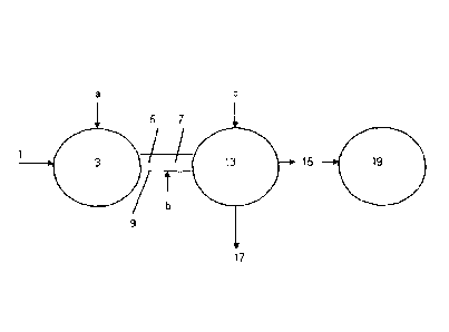
Figure 1 shows a layout of the apparatus which may be used in the present
invention.
Figure 2 shows a flowchart of the steps in the process of the present
invention.
As shown in figure 1, an RDF waste source 1 is subjected to an initial pre-
treatment step (optional) which involved homogenisation. The RDF was then
passed in a continuous process into a gasification unit 3 where it was
gasified at
a temperature of approximately 8000. The gasification process produced an
offgas 5 and a solid non-airborne char 7 which were passed from the
gasification
unit 3 within an airtight conduit 9 with a conveyor belt (not shown) toa
plasma
treatment unit 13.
CA 2832892 2017-09-15
CA 02832892 2013-10-09
WO 2011/138591
PCT/GB2011/000699
- 36 -
In the plasma treatment unit 13 the offgas 5 and a solid non-airborne char 7
were
plasma treated in the presence of oxygen and steam to form a syngas 15 and a
solid vitrified waste 17. The syngas 15 was passed to a gas turbine 19 for
energy
production.
A hazardous waste material 21 (not shown) was obtained in a batchwise manner.
It was assessed in parallel with the processing of the RDF waste source 1 to
determine where it should be blended in. Accordingly, the hazardous waste
material 21 was blended into the process by passing it through an airlock at
a, b,
or c depending on the hazardous waste material's 21 characteristics.
As shown in figure 2, the refuse derived fuel 1 is gasified to produce an
offgas 5
and a solid non-airborne char 7. These are plasma treated to produce a syngas
and a vitrified solid 17. The hazardous waste material 21 is assessed and
15 introduced into the process. Accordingly, the hazardous waste material
21, once
treated, will form part of at least one of the offgas 5, the solid non-
airborne char 7,
the syngas 15 and the vitrified solid 17.
The foregoing detailed description has been provided by way of explanation and
illustration, and is not intended to limit the scope of the appended claims.
Many
variations in the presently preferred embodiments illustrated herein will be
apparent to one of ordinary skill in the art, and remain within the scope of
the
appended claims and their equivalents.