Language selection

Search

Patent 2833014 Summary

Third-party information liability

Some of the information on this Web page has been provided by external sources. The Government of Canada is not responsible for the accuracy, reliability or currency of the information supplied by external sources. Users wishing to rely upon this information should consult directly with the source of the information. Content provided by external sources is not subject to official languages, privacy and accessibility requirements.

Claims and Abstract availability

Any discrepancies in the text and image of the Claims and Abstract are due to differing posting times. Text of the Claims and Abstract are posted:

  • At the time the application is open to public inspection;
  • At the time of issue of the patent (grant).
(12) Patent Application: (11) CA 2833014
(54) English Title: HYDRAULIC BUCKET APPARATUS
(54) French Title: APPAREIL A BENNE HYDRAULIQUE
Status: Deemed Abandoned and Beyond the Period of Reinstatement - Pending Response to Notice of Disregarded Communication
Bibliographic Data
(51) International Patent Classification (IPC):
  • E02F 03/413 (2006.01)
  • B66C 03/02 (2006.01)
(72) Inventors :
  • MIRE, MICHAEL (United States of America)
  • NAQUIN, JOEY (United States of America)
(73) Owners :
  • GULFSTREAM SERVICES, INC.
(71) Applicants :
  • GULFSTREAM SERVICES, INC. (United States of America)
(74) Agent: GOWLING WLG (CANADA) LLP
(74) Associate agent:
(45) Issued:
(86) PCT Filing Date: 2012-04-12
(87) Open to Public Inspection: 2012-10-18
Availability of licence: N/A
Dedicated to the Public: N/A
(25) Language of filing: English

Patent Cooperation Treaty (PCT): Yes
(86) PCT Filing Number: PCT/US2012/033266
(87) International Publication Number: US2012033266
(85) National Entry: 2013-10-10

(30) Application Priority Data:
Application No. Country/Territory Date
61/474,623 (United States of America) 2011-04-12

Abstracts

English Abstract

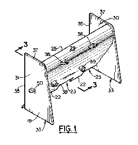
A hydraulic clamshell bucket apparatus employs a frame that includes an upper lifting member that enables the frame to be lifted with a crane or other lifting device. First and second hydraulically powered jaws are each attached to the frame. Jaw pivots are provided on the frame, each jaw pivotally attached to the frame at a jaw pivot. First and second hydraulic cylinders are each connected to the frame. Each cylinder pivots on the frame above the jaw pivots, each cylinder connected to the frame at an upper cylinder pivot. Lower cylinder pivots are provided on the jaws, each cylinder pivotally attached to a jaw at a lower cylinder pivot. Each jaw has a concave surface. First and second digging implements are attached to the jaws, the first digging implement attached to the first jaw, the second digging implement attached to the second jaw. Each digging implement has a concave portion. Each digging implement is wider than the jaw to which it is attached so that each implement extends laterally away from the jaw to which it is attached. A pair of side panels is attached to each digging implement at positions spaced away from the jaws.


French Abstract

La présente invention a trait à un appareil à benne preneuse hydraulique qui emploie un cadre qui inclut un élément de levage supérieur qui permet au cadre d'être levé au moyen d'une grue ou d'un autre dispositif de levage. Des première et seconde mâchoires à commande hydraulique sont chacune attachées au cadre. Des pivots de mâchoire sont prévus sur le cadre, chaque mâchoire étant attachée de façon pivotante au cadre au niveau d'un pivot de mâchoire. Des premier et second vérins hydrauliques sont chacun connectés au cadre. Chaque vérin pivote sur le cadre au-dessus des pivots de mâchoire, chaque vérin étant connecté au cadre au niveau d'un pivot de vérin supérieur. Des pivots de vérin inférieurs sont prévus sur les mâchoires, chaque vérin étant attaché de façon pivotante à une mâchoire au niveau d'un pivot de vérin inférieur. Chaque mâchoire est dotée d'une surface concave. Des premier et second accessoires d'excavation sont attachés aux mâchoires, le premier accessoire d'excavation étant attaché à la première mâchoire, le second accessoire d'excavation étant attaché à la seconde mâchoire. Chaque accessoire d'excavation est doté d'une partie concave. Chaque accessoire d'excavation est plus large que la mâchoire à laquelle il est attaché de sorte que chaque accessoire s'étend latéralement en s'éloignant de la mâchoire à laquelle il est attaché. Une paire de panneaux latéraux est attachée à chaque accessoire d'excavation à des positions éloignées des mâchoires.

Claims

Note: Claims are shown in the official language in which they were submitted.


CLAIMS
1. A hydraulic clamshell bucket apparatus,
comprising:
a) a frame that includes an upper lifting member
that enables the frame to be lifted with a crane or other
lifting device;
b) first and second hydraulically powered jaws, each
jaw pivotally attached to the frame at provided jaw pivots
and in a plane of jaw movement;
c) first and second hydraulic cylinders, each
cylinder connected to the frame;
d) upper cylinder pivots on the frame above the jaw
pivots, each cylinder connected to the frame at an upper
cylinder pivot;
e) lower cylinder pivots on the jaws, each cylinder
pivotally attached to a jaw at a lower cylinder pivot;
f) each jaw having a concave surface;
g) first and second digging implements attached to the
jaws, the first digging implement attached to the first
jaw, the second digging implement attached to the second
jaw;
h) each digging implement having concave portions,
each digging implement extending laterally away from the
jaws; and
i) side panels attached to the digging implement at
positions spaced away from the jaws, said side panels
generally parallel with the said plane of jaw movement.
2. The hydraulic clamshell bucket apparatus of claim
1 wherein the side panels of each implement are parallel.
3. The hydraulic clamshell bucket apparatus of claim
1 wherein the side panels have generally horizontal
surfaces.
4. The hydraulic clamshell bucket apparatus of claim
1 wherein each implement is removably attached to a said
jaw.
-9-

5. The hydraulic clamshell bucket apparatus of claim
4 wherein each implement is bolted to a said jaw.
6. The hydraulic clamshell bucket apparatus of claim
1 wherein there are connections that connect each implement
to a said jaw, said connections being in between said side
panels.
7. The hydraulic clamshell bucket apparatus of claim
1 wherein each implement has a flat surface portion.
8. The hydraulic clamshell bucket apparatus of claim
1 wherein each implement has a toothed portion.
9. The hydraulic clamshell bucket apparatus of claim
8 wherein each side panel has a lower surface that extends
horizontally to the rear of the toothed portion of a said
implement.
10. A hydraulic clamshell bucket apparatus,
comprising:
a) a frame;
b) first and second hydraulically powered jaws, each
jaw attached to the frame at provided jaw pivots;
c) first and second hydraulic cylinders, each
cylinder connected to the frame;
d) upper cylinder pivots on the frame above the jaw
pivots, each cylinder connected to the frame at an upper
cylinder pivot;
e) lower cylinder pivots on the jaws, each cylinder
pivotally attached to a jaw at a lower cylinder pivot;
f) first and second digging implements attached to the
jaws, the first digging implement attached to the first
jaw, the second digging implement attached to the second
jaw;
g) each digging implement having concave portions,
each digging implement extending laterally away from the
jaws in two directions; and
h) a plurality of four side panels attached to the
digging implement, one side panel attached to each digging
-10-

implement at positions spaced away from the jaws and on
opposing sides of each digging implement.
11. A hydraulic clamshell bucket apparatus,
comprising:
a) a frame that includes an upper lifting portion
that enables the frame to be lifted with a crane or other
lifting device;
b) first and second hydraulically powered jaws, each
jaw pivotally attached to the frame at provided jaw pivots;
c) each jaw having a concave surface;
d) first and second digging implements attached to the
jaws, the first digging implement attached to the first
jaw, the second digging implement attached to the second
jaw;
e) each digging implement having concave portions, a
pair of side edges, an upper edge, a lower edge, and each
digging implement extending laterally away from the jaws;
f) side panels attached to the digging implement at
positions spaced away from the jaws; and
g) wherein a said side edge is connected to a said
side panel.
12. The hydraulic clamshell bucket apparatus of claim
11 wherein the side panels of each implement are parallel.
13. The hydraulic clamshell bucket apparatus of claim
11 wherein the side panels have generally horizontal
surfaces.
14. The hydraulic clamshell bucket apparatus of claim
11 wherein each implement is removably attached to a said
jaw.
15. The hydraulic clamshell bucket apparatus of
claim 14 wherein each implement is bolted to a said jaw.
16. The hydraulic clamshell bucket apparatus of
claim 11 wherein there are connections that connect each
implement to a said jaw, said connections being in between
said side panels.
-11-

17. The hydraulic clamshell bucket apparatus of claim
11 wherein each implement has a flat surface portion.
18. The hydraulic clamshell bucket apparatus of claim
11 wherein each implement has a toothed portion.
19. The hydraulic clamshell bucket apparatus of
claim 18 wherein each side panel has a lower surface that
extends horizontally to the rear of the toothed portion of
a said implement.
20. A hydraulic clamshell bucket apparatus,
comprising:
a) a frame;
b) first and second hydraulically powered jaws, each
jaw movable between open and closed positions, said jaws
attached to the frame at provided jaw pivots;
c) first and second hydraulic cylinders, each
cylinder connected to the frame;
d) upper cylinder pivots on the frame above the jaw
pivots, each cylinder connected to the frame at an upper
cylinder pivot;
e) lower cylinder pivots on the jaws, each cylinder
pivotally attached to a jaw at a lower cylinder pivot;
f) first and second digging implements attached to
the jaws, the first digging implement attached to the first
jaw, the second digging implement attached to the second
jaw;
g) each digging implement having concave portions,
a pair of side edges, an upper edge, a lower edge, and each
digging implement extending laterally away from the jaws;
h) side panels attached to the digging implement at
positions spaced away from the jaws;
i) first and second digging implements attached to
the jaws, the first digging implement attached to the first
jaw, the second digging implement attached to the second
jaw; and
j) wherein the side panels of each pair of jaws have
-12-

correspondingly shaped abutting edges that abut when the
jaws move to the closed position.
-13-

Description

Note: Descriptions are shown in the official language in which they were submitted.


CA 02833014 2013-10-10
WO 2012/142247
PCT/US2012/033266
PATENT APPLICATION
US Attorney Docket No. A11009US (99233.15)
PCT Attorney Docket No. A11009W0 (99233.15W0)
TITLE OF THE INVENTION
HYDRAULIC BUCKET APPARATUS
INVENTORS: MIRE, Michael, a US citizen, of 34 Cycas,
Kenner, LA, 70065, US; and
NAQUIN, Joey, a US citizen, of 9499 East
Main St., Houma, LA 70363, US.
ASSIGNEE: GULFSTREAM SERVICES, INC., a Louisiana, US,
corporation, having an address of 103
Dickson Road, Houma, LA 70363, US.
CROSS-REFERENCE TO RELATED APPLICATIONS
This is a nonprovisional patent application of US
Provisional Patent Application Serial No. 61/474,623, filed
12 April 2011, which is hereby incorporated herein by
reference.
Priority of US Provisional Patent Application Serial
No. 61/474,623, filed 12 April 2011, incorporated herein by
reference, is hereby claimed.
STATEMENT REGARDING FEDERALLY SPONSORED RESEARCH OR
DEVELOPMENT
Not applicable
REFERENCE TO A "MICROFICHE APPENDIX"
Not applicable
BACKGROUND OF THE INVENTION
1. Field of the Invention
The present invention relates to a method and
apparatus for excavating dense clay material in a marine
environment.
2. General Background of the Invention
Plug and abandonment of an oil well typically utilizes
cold cutting of the sections of tubulars as they are
removed from the well. This cold cutting is done with a
-1-

CA 02833014 2013-10-10
WO 2012/142247
PCT/US2012/033266
saw. Another method of cutting tubulars that are being
removed from an oil well is to manually cut with a cutting
torch. However, such use of cutting torches can generate
injury or death if a pocket of natural gas is trapped in
between layers of casing or tubing. Such a pocket of gas
can be ignited by the open flame of a cutting torch,
generating an explosion. The
cutting and removal of
sections of tubular production pipe, production casing or
the like from an oil well also requires removal of part of
the marine sediment, which can be a very dense clay
material that is not easily removed. At times, the only
effective way to remove such bottom sediment is with an
underwater cutting device operated by a diver.
BRIEF SUMMARY OF THE INVENTION
The present invention provides a hydraulic clamshell
bucket apparatus having a frame that includes an upper
lifting member that enables the frame to be lifted with a
crane or other lifting device.
First and second hydraulically powered jaws are
supported below the frame, each jaw pivotally attached to
the frame.
Upper frame pivots are provided on the frame, each jaw
pivotally attached to the frame at a said frame pivot.
First and second hydraulic cylinders are provided,
each pivotally connected to the frame.
Cylinder pivots on the frame are provided above the
jaw pivots, each cylinder connected to the frame at a
cylinder pivot.
Lower cylinder pivots are provided on the jaws, each
cylinder pivotally attached to a jaw at a lower cylinder
pivot.
Each jaw can have a concave surface and a flat
surface.
First and second digging implements are attached to
the jaws. The first digging implement is attached to the
-2-

CA 02833014 2013-10-10
WO 2012/142247
PCT/US2012/033266
first jaw. The second digging implement is attached to the
second jaw.
Each digging implement has concave portions. Each
digging implement extends laterally away from the jaws.
Side panels are attached to the digging implement at
positions spaced away from the jaws.
BRIEF DESCRIPTION OF THE SEVERAL VIEWS OF THE DRAWINGS
For a further understanding of the nature, objects,
and advantages of the present invention, reference should
be had to the following detailed description, read in
conjunction with the following drawings, wherein like
reference numerals denote like elements and wherein:
Figure 1 is a partial perspective view of a preferred
embodiment of the apparatus of the present invention;
Figure 2 is a partial perspective view of a preferred
embodiment of the apparatus of the present invention;
Figure 3 is a sectional view taken along lines 3-3 of
Figure 1;
Figure 4 is a sectional view taken along lines 3-3 of
Figure 1;
Figure 5 is a perspective view of a preferred
embodiment of the apparatus of the present invention;
Figure 6 is a perspective view of a preferred
embodiment of the apparatus of the present invention;
Figure 7 is an elevation view of a preferred
embodiment of the apparatus of the present invention;
Figure 8 is an elevation view of a preferred
embodiment of the apparatus of the present invention
showing the apparatus as it engages a sea bed;
Figure 9 is an elevation view of a preferred
embodiment of the apparatus of the present invention
showing a removal of material from a sea bed;
Figure 10 is an elevation view of a preferred
embodiment of the apparatus of the present invention
showing a removal of material from a sea bed;
-3-

CA 02833014 2013-10-10
WO 2012/142247
PCT/US2012/033266
Figure 11 is a perspective view of a preferred
embodiment of the apparatus of the present invention;
Figure 12 is a perspective view of a preferred
embodiment of the apparatus of the present invention;
Figure 13 is a perspective view of a preferred
embodiment of the apparatus of the present invention;
Figure 14 is a side sectional view of a preferred
embodiment of the apparatus of the present invention with
jaws closed; and
Figure 15 is a side sectional view of a preferred
embodiment of the apparatus of the present invention with
jaws opened.
DETAILED DESCRIPTION OF THE INVENTION
Figures 5-15 show a preferred embodiment of the
apparatus of the present invention, designated generally by
the numeral 10. Hydraulic clamshell bucket 10 can be moved
into position for work using a lifting line or a sling 11.
The lifting line or sling 11 can form a connection with the
hydraulic clamshell bucket 10 body 12 at shackle 13.
As shown in Figure 5, the body or frame 12 supports a
pair of hydraulically powered jaws 14, 15. Each jaw 14, 15
has a pivot or pivotal attachment to body 12. Jaw 14 has
a pivotal attachment to body 12 at pivot 16. Jaw 15 has a
pivotal attachment to body 12 at pivot 17.
Figures 14 and 15 show a first extensible hydraulic
cylinder 55 that is attached to frame 12 and to jaw 14. A
second extensible hydraulic cylinder 56 is attached to
frame 12 and to jaw 15. The cylinder 55 has upper cylinder
pivot (or pivotal connection) 57 wherein jaw 14 attaches to
frame 12 and lower cylinder pivot 58 where cylinder 55
attaches to jaw 14.
Similarly, cylinder 56 has upper
cylinder pivot 59 where cylinder 56 attaches to frame 12
and lower cylinder pivot 60 where cylinder 56 attaches to
jaw 15.
When cylinders 55, 56 retract, the jaws 14, 15 open to
-4-

CA 02833014 2013-10-10
WO 2012/142247
PCT/US2012/033266
the position of figures 7, 8, and 15. When the cylinders
55, 56 extend, the jaws 14, 15 close to the position of
figures 9-14.
A digging implement or bucket half 18, 19 is provided
for attachment to each jaw 14, 15. Each bucket half has
teeth 20, 22 and recesses 21, 23 in between teeth as shown
in Figures 1 and 2. Each digging implement or bucket half
18, 19 has recesses in between the teeth. Recesses 21 are
provided in between teeth 20. Recesses 23 are provided in
between teeth 22.
Each implement 18, 19 has an upper edge. The
implement or bucket half 18 has upper edge 24. The
implement or bucket half 19 has upper edge 25.
Each digging implement or bucket half 18, 19 has a
blade. The implement 18 has blade 26 with side panels 27,
28. The implement 19 has blade 29 with side panels 30, 31.
Each of the side panels 27, 28 and 30, 31 has a bottom
edge. For the implement 18, each of the side panels 27, 28
provides bottom edges 32. For the implement 19, each of
the side panels 30, 31 have bottom edges 33. Each of the
side panels 27, 28 and 30, 31 provides inner edges. The
side panels 27, 28 have inner edges 34. The side panels
30, 31 each have an inner edge 35. During use, the edges
34, 35 engage and abut when the apparatus 10 is in a closed
position as shown in Figure 6.
Each of the side panels have upper edges. The side
panels 27, 28 have upper edges 36. The side panels 30, 31
each have upper edges 37. A plurality of padeyes or lugs
are provided on each of the implements 18, 19. These lugs
include upper lugs or padeyes 38 and lower lugs or padeyes
39 as shown in Figure 1. Each of the jaws 14, 15 of the
body or frame 12 has a plurality of lugs or padeyes 40, 41.
These include upper lugs or padeyes 40 and lower lugs or
padeyes 41 as shown in Figure 5. Bolted connections are
used to assemble the lugs or padeyes of the jaws 14, 15
-5-

CA 02833014 2013-10-10
WO 2012/142247
PCT/US2012/033266
with the lugs or padeyes of the implements 18, 19. Bolted
connections 42 can be used to connect a lug or padeye of a
jaw 14 or 15 to a lug or padeye of an implement 18 or 19
(see Figure 6).
The upper and lower lugs or padeyes 40, 41 on the jaws
14, 15 can be seen in Figures 4-6. Arrows 43 in Figure 4
illustrate the attachment of the lugs 40, 41 to the jaws
14, 15. This
attachment can be a welded attachment for
example. The lugs or padeyes 38, 39 on the implements 18,
19 can be seen in Figures 1-3, 5, and 6.
Each implement 18, 19 has blades 26, 29. Each blade
26, 29 has concave and flat surfaces. For the implement
18, the blade 26 has concave surface 44 and flat surface
46, as shown in Figure 5. For the implement 19, the blade
29 has concave surface 45 and flat surface 47, as shown in
Figure 3. For each of the implements 18, 19 the location
48 shows the joint between its concave surface and its flat
surface. For example, in Figure 3, the concave surface 45
meets the flat surface 47 at location 48.
Each implement 18, 19 has a lifting eye 49. The
lifting eye 49 is attached to the concave 44 surface of
blade 26 of implement 18 as shown in Figure 5 and at
concave surface 45 of blade 25 of implement 19 as shown in
Figure 3. The lifting eye 49 can be at a position next to
upper edge 25 as shown in Figure 3.
Each implement 18, 19 has a padeye or lug 50 on each
of its side panels 27, 28, 30, 31 as shown in Figures 1, 2,
3 and 12-13. When it is desired to handle the implements
18, 19 before or after they have been assembled to the body
or frame 12, the implements 18, 19 can be joined together
using slings 51 wherein the sling 51 is attached to the
padeyes 50 of the side panels 27, 28, 30, 31 as shown in
Figures 12 and 13. This assembly of implements 18, 19 can
be lifted using lift lines or slings 52 attached to a hook
53 of a crane lifting line 54.
-6-

CA 02833014 2013-10-10
WO 2012/142247
PCT/US2012/033266
The following is a list of parts and materials
suitable for use in the present invention:
PARTS LIST
Parts Number Description
hydraulic clamshell bucket
11 lifting line/sling
12 body/frame
13 shackle
14 jaw
jaw
16 pivot
17 pivot
18 bucket half/implement
19 bucket half/implement
tooth
21 recess
22 tooth
23 recess
24 upper edge
upper edge
26 blade
27 side panel
28 side panel
29 blade
side panel
31 side panel
32 bottom edge
33 bottom edge
34 inner edge
inner edge
36 upper edge
37 upper edge
38 upper lug/padeye
39 lower lug/padeye
-7-

CA 02833014 2013-10-10
WO 2012/142247
PCT/US2012/033266
40 upper lug/padeye
41 lower lug/padeye
42 bolted connection
43 arrow
44 concave surface
45 concave surface
46 flat surface
47 flat surface
48 location
49 lifting eye
50 padeye/lug
51 sling
52 lift line/sling
53 hook
54 lift line
55 first hydraulic cylinder
56 second hydraulic cylinder
57 upper cylinder pivot/pivotal
connection
58 lower cylinder pivot/pivotal
connection
59 upper cylinder pivot/pivotal
connection
60 lower cylinder pivot/pivotal
connection
All measurements disclosed herein are at standard
temperature and pressure, at sea level on Earth, unless
indicated otherwise.
The foregoing embodiments are presented by way of
example only; the scope of the present invention is to be
limited only by the following claims.
-8-

Representative Drawing
A single figure which represents the drawing illustrating the invention.
Administrative Status

2024-08-01:As part of the Next Generation Patents (NGP) transition, the Canadian Patents Database (CPD) now contains a more detailed Event History, which replicates the Event Log of our new back-office solution.

Please note that "Inactive:" events refers to events no longer in use in our new back-office solution.

For a clearer understanding of the status of the application/patent presented on this page, the site Disclaimer , as well as the definitions for Patent , Event History , Maintenance Fee  and Payment History  should be consulted.

Event History

Description Date
Time Limit for Reversal Expired 2016-04-13
Application Not Reinstated by Deadline 2016-04-13
Deemed Abandoned - Failure to Respond to Maintenance Fee Notice 2015-04-13
Inactive: Cover page published 2013-11-28
Inactive: Notice - National entry - No RFE 2013-11-20
Inactive: IPC assigned 2013-11-20
Application Received - PCT 2013-11-20
Inactive: First IPC assigned 2013-11-20
Inactive: IPC assigned 2013-11-20
National Entry Requirements Determined Compliant 2013-10-10
Application Published (Open to Public Inspection) 2012-10-18

Abandonment History

Abandonment Date Reason Reinstatement Date
2015-04-13

Maintenance Fee

The last payment was received on 2013-10-10

Note : If the full payment has not been received on or before the date indicated, a further fee may be required which may be one of the following

  • the reinstatement fee;
  • the late payment fee; or
  • additional fee to reverse deemed expiry.

Patent fees are adjusted on the 1st of January every year. The amounts above are the current amounts if received by December 31 of the current year.
Please refer to the CIPO Patent Fees web page to see all current fee amounts.

Fee History

Fee Type Anniversary Year Due Date Paid Date
Basic national fee - standard 2013-10-10
MF (application, 2nd anniv.) - standard 02 2014-04-14 2013-10-10
Owners on Record

Note: Records showing the ownership history in alphabetical order.

Current Owners on Record
GULFSTREAM SERVICES, INC.
Past Owners on Record
JOEY NAQUIN
MICHAEL MIRE
Past Owners that do not appear in the "Owners on Record" listing will appear in other documentation within the application.
Documents

To view selected files, please enter reCAPTCHA code :


To view images, click a link in the Document Description column. To download the documents, select one or more checkboxes in the first column and then click the "Download Selected in PDF format (Zip Archive)" or the "Download Selected as Single PDF" button.

List of published and non-published patent-specific documents on the CPD .

If you have any difficulty accessing content, you can call the Client Service Centre at 1-866-997-1936 or send them an e-mail at CIPO Client Service Centre.


Document
Description 
Date
(yyyy-mm-dd) 
Number of pages   Size of Image (KB) 
Description 2013-10-09 8 272
Abstract 2013-10-09 1 78
Drawings 2013-10-09 9 270
Claims 2013-10-09 5 154
Representative drawing 2013-11-20 1 12
Notice of National Entry 2013-11-19 1 193
Courtesy - Abandonment Letter (Maintenance Fee) 2015-06-07 1 173
PCT 2013-10-09 7 314