Note: Descriptions are shown in the official language in which they were submitted.
CA 2833088 2017-05-11
1
PROCESS FOR DETERMINING POSITION PARAMETERS OF A
MANUFACTURED SURFACE RELATIVE TO A REFERENCE SURFACE
FIELD OF THE INVENTION
The invention relates to a process implemented by computer
means for determining position parameters defining the relative
position of a manufactured derivable surface relative to a
reference surface, to a manufacturing process and to a process
for controlling such manufacturing process.
BACKGROUND OF THE INVENTION
Optical lenses, and in particular ophthalmic lenses, require
very high quality manufacturing process in order to obtain high
quality optical lenses.
Historically, optical lenses have been manufactured by
different processes such as cast molding.
However, the molding method presents limitation in terms of
cost.
Therefore, new manufacturing techniques such as digital
surfacing are used.
Whereas to control the quality of the lenses produced using
cast molding process, one can check the quality of the mold
being used, such quality control is not possible when using the
digital surfacing process. One could check each individual lens
however such quality control would be very time consuming and
present a limitation in terms of costs.
CA 2833088 2017-05-11
2
Therefore, quality control process has been developed that
allow controlling the quality of the lenses produced using a
digital surfacing process by controlling the quality of the
manufacturing process itself. An example of such a process that
allows checking efficiently the quality of the digital
surfacing process is disclosed in EP 08 853 275.
The inventors have observed that the results provided by such
process may not be entirely satisfactory. In particular, the
inventors have observed that after such analyzing process the
results may comprise certain artifacts.
SUMMARY OF THE INVENTION
Therefore, there is a need to improve such quality analyzing
process in order to strengthen the control of the manufacturing
process and the quality of manufactured lenses. Thus, a goal of
the present invention is to provide such a analyzing process.
The invention relates to a process implemented by computer
means for determining position parameters defining the relative
position of a manufactured derivable surface relative to a
reference surface, the process comprising:
- a nominal surface providing step during which a nominal
surface expressed in a nominal frame of reference and
corresponding to the theoretical derivable surface to be
manufactured with the nominal value of the position
parameters defining the relative position of the nominal
surface relative to the reference surface is provided,
- a measured surface providing step during which a measured
surface of the manufactured derivable surface expressed in
the nominal frame of reference is provided,
CA 2833088 2017-05-11
3
- a deformation surface providing step during which at least
one deformation surface defined by at least one
deformation adjustable parameter is provided,
- a composed surface determining step during which a
composed surface is determined by adding the measured
surface and the deformation surface,
- a parameters determining step during which the position
parameters and at least one deformation parameter are
determined by minimizing the difference between the
nominal surface and the composed surface.
Advantageously, the method according to the invention allows
determining the position parameters defining the relative
position of the manufactured derivable surface relative to the
reference surface.
Indeed, the inventors have observed that the positioning
parameters are first-order factors in the quality measurements
of any digital surfacing process.
The position parameters that are determined using the process
according to the invention comprise less artifact than when
obtained using the method of the prior art. Furthermore, the
process according to the invention allows determining at least
one deformation parameter.
According to further embodiments which can be considered alone
or in combination:
- the parameter determining step further comprises a zone
determining step in which a zone of interest is determined
in the nominal surface and the position and deformation
parameters are determined by minimizing the difference
CA2133308820171
4
between the nominal surface and the composed surface in
the zone of interest; and/or
- the parameter determining step is implemented by using a
damped least squares process; and/or
- the manufactured derivable surface is a surface of an
ophthalmic lens; and/or
- the measured surface is
determined by optical
measurements; and/or
- the manufactured derivable surface is a non-symmetric
derivable surface; and/or
- the position parameters comprise at least six parameters,
for example three translation coefficients and three
rotation coefficients; and/or
- the deformation surface corresponds to a sphero-torus
surface defined by a sphere parameter, a cylinder
parameter and an axis parameter; and/or
- the deformation surface corresponds to a right circular
cone defined by an axis parameter and an angle parameter.
According to another aspect, the invention relates to a process
for controlling a manufacturing process, comprising the steps
of the above-described process and further comprising:
- an error surface determining step during which the error
surface corresponding to the difference between the
measured surface positioned relative to the reference
surface by using the six position parameters and the
nominal surface is deteimined,
- a controlling step during which the error surface is
controlled.
CA2133820171
5 The invention also relates to a process for controlling a lens
manufacturing process comprising the steps of:
a) manufacturing a master lens according to a manufacturing
process using a manufacturing device,
b) determining by the process according to the invention at
least one deformation parameter of the master lens of step
a),
c) recording the value of the at least one deformation
parameter,
d) repeating regularly step a) to c) and checking the
evolution of the at least one deformation parameter over
time,
wherein the evolution of at least one parameter of the
manufacturing device used during the lens manufacturing process
is checked over time and the evolution over time of at least
one deformation parameter of the master lens is related with
the evolution over time of the at least one parameter of the
manufacturing device.
The invention further relates to a manufacturing process for
manufacturing a lens using a manufacturing device comprising
the steps of:
- providing a lens blank,
- blocking the lens blank,
- surfacing at least one surface of the lens blank,
said manufacturing process being checked by a process according
to the invention.
According to an embodiment, the process includes an ophthalmic
progressive lens surfacing process, for example a digital
surfacing process.
CA2133820171
6
The invention also relates to a computer program product for a
data processing device, the computer program product comprising
a set of instructions which, when loaded into the data
processing device, causes the data processing device to perform
at least one of the steps, for example all of the steps, of the
method according to the invention.
In addition, the present invention provides a computer-readable
medium carrying one or more set of instructions of a computer
program product of the invention.
Unless specifically stated otherwise, as apparent from the
following discussions, it is appreciated that throughout the
specification discussions utilizing terms such as "computing",
"calculating", "generating", or the like, refer to the action
and/or processes of a computer or computing system, or similar
electronic computing device, that manipulate and/or transform
data represented as physical, such as electronic, quantities
within the computing system's registers and/or memories into
other data similarly represented as physical quantities within
the computing system's memories, registers or other such
information storage, transmission or display devices.
Embodiments of the present invention may include apparatuses
for performing the operations herein. This apparatus may be
specially constructed for the desired purposes, or it may
comprise a general purpose computer or Digital Signal Processor
("DSP") selectively activated or reconfigured by a computer
program stored in the computer. Such a computer program may be
stored in a computer readable storage medium, such as, but is
not limited to, any type of disk including floppy disks,
optical disks, CD-ROMs, magnetic-optical disks, read-only
CA2133820171
7
memories (ROMs), random access memories (RAMs) electrically
programmable read-only memories (EPROMs), electrically erasable
and programmable read only memories (EEPROMs), magnetic or
optical cards, or any other type of media suitable for storing
electronic instructions, and capable of being coupled to a
computer system bus. The processes and displays presented
herein are not inherently related to any particular computer or
other apparatus. Various general purpose systems may be used
with programs in accordance with the teachings herein, or it
may prove convenient to construct a more specialized apparatus
to perform the desired method. The desired structure for a
variety of these systems will appear from the description
below. In addition, embodiments of the present invention are
not described with reference to any particular programming
language. It will be appreciated that a variety of programming
languages may be used to implement the teachings of the
inventions as described herein.
In the sense of the invention "the manufacturing parameters"
are the setting parameter of the different manufacturing
devices involved in the manufacturing process. In the sense of
the invention "the process parameter" includes any measurable
parameters on the manufacturing devices used for the
manufacturing of the lens.
BRIEF DESCRIPTION OF THE DRAWINGS
Non limiting embodiments of the invention will now be described
with reference to the accompanying drawing wherein:
CA2133308820171
8
FIGS. la to lc illustrate the influence of the positioning
parameters of a surface of an ophthalmic lens on the
distribution of astigmatism of said lens;
FIGS. 2a to 2d illustrate the results of a prior art process
for determining the difference between a nominal surface and a
measured surface;
FIGS. 3a to 3d illustrate the results of a prior art process
for determining the difference between a nominal surface and a
measured surface;
FIG. 4 is a flowchart of the steps comprised in a process for
determining the positioning parameters according to an
embodiment of the invention;
FIG. 5 is a flowchart of the steps comprised in a manufacturing
process according to an embodiment of the invention; and
FIG. 6 is a flowchart of the steps comprised in a controlling
process according to an embodiment of the invention.
DETAILED DESCRIPTION OF THE DRAWINGS
FIGS. la to lc illustrate the effect of an error on the
positioning parameters on the astigmatism of the resulting
ophthalmic lens.
FIGS. la to lc are two dimensional maps of a progressive
addition lens of the type Varilux0 PanamicTM with a front face
of 2.12 dioptres and a rear face with a sphere of -7.75 a
cylinder of 2.75 and addition of 2.75.
CA2133820171
9
The two dimensional maps represent the distribution of
astigmatism as perceived by the wearer.
FIG. la to lc the front and back surfaces of the lens are the
same the only differences lay in the position of the back
surface.
In FIG. la the back surface is correctly positioned.
In FIG. lb, the back surface is translated of 2 mm along the x-
axis and the y-axis.
In FIG. lc, the back surface is translated of 2 mm along the x-
axis and the y-axis and rotated of 5'degree. around the a-axis.
As it appears from FIGS. la to lc, the difference in position
of the back surface implies a great effect on the distribution
of astigmatism as perceived by the wearer.
Thus, it is of great importance to be able to determine
correctly the positioning parameters of the back surface.
Besides, it is important not to mix up these changes of
distribution of astigmatism (or power error) with changes
caused by surface deformation. It is of great importance to be
able to separate and distinguish the real causes of changes of
distribution of wearer astigmatism (or more generally wearer
power error), for both positioning errors and surface
deformation errors.
FIGS. 2 and 3 provide examples of the influence of the
deformation step of the process according to the invention.
In the example of FIGS. 2a to 2d a nominal progressive surface
is compared to deformed progressive surface. The deformed
CA 2833088 2017-05-11
5 progressive surface corresponds to the nominal progressive
surface to which a spherical deformation of 0.1 dioptre was
added.
When comparing the nominal and deformed surfaces, one should
obtain a third surface correspond to a part of a sphere of 0.1
10 diopter.
FIGS. 2a to 2d illustrate the features of a third surface
corresponding to the difference between the nominal surface and
the deformed surface obtained using a prior art process. Such
prior art process consist in determining the position parameter
that minimize the difference between the deformed surface and
the nominal surface.
The inventors have run the prior art process as if the deformed
surface was a measured surface corresponding to a manufactured
surface. The prior art process provides the position parameters
of the deformed surface. By using such position parameters one
can determine the features of corresponding ophthalmic lens.
The features of the determined ophthalmic lens are represented
on FIGS. 2a to 2d.
FIG. 2a represents the power profile of the sags difference
between the measured progressive lens and its nominal surface,
obtained using the prior art process.
FIG. 2b represents the sphere distribution of this difference
obtained using the prior art process.
FIG. 2c represents the cylinder distribution of this difference
obtained using the prior art process.
CA2133820171
11
FIG. 2d represents the gap in microns between the measured
progressive lens and its nominal surface, obtained using the
prior art process.
Since the difference between the nominal surface and the
progressive surface is a uniform deformation of 0.1 diopter,
the power profile represented in FIG. 2a should be a straight
line corresponding to 0.1 diopter and the sphere and cylinder
distributions should be blank since the sphere should always be
equal to 0.1 diopter and the cylinder should be equal to 0.
As illustrated by FIGS. 2a to 2d, the prior art process results
in generating differences between the nominal surface and the
deformed surface that actually do not exists.
In the example of FIGS. 3a to 3d a nominal progressive surface
is compared to deformed progressive surface. The deformed
progressive surface corresponds to the nominal progressive
surface to which a progressive surface of 0.1 diopter of
addition was added.
When comparing the nominal and deformed surfaces, one should
obtain a third surface correspond to a progressive surface of
0.1 diopter of addition
FIGS. 3a to 3d illustrate the features of a third surface
corresponding to the difference between the nominal surface and
the deformed surface obtained using a prior art process. Such
prior art process consist in determining the position parameter
that minimize the difference between the deformed surface and
the nominal surface.
CA 2833088 2017-05-11
12
The inventors have run the prior art process as if the deformed
surface was a measured surface corresponding to a manufactured
surface. The prior art process provides the position parameters
of the deformed surface. By using such position parameters one
can determine the features of corresponding ophthalmic lens.
The features of the determined ophthalmic lens are represented
on FIGS. 3a to 3d.
FIG. 3a represents the power profile of the sags difference
between of the measured surface of the progressive lens and its
nominal surface, obtained using the prior art process.
FIG. 3b represents the sphere distribution of this difference
obtained using the prior art process.
FIG. 3c represents the cylinder distribution of this difference
obtained using the prior art process.
FIG. 3d represents the gap in microns between the measured
progressive lens and its nominal surface, obtained using the
prior art process.
The difference between the nominal surface and the deformation
surface should be a progressive surface of 0.1 D of addition.
As illustrated by FIGS. 3a to 3d, the prior art process results
in generating differences between the nominal surface and the
deformed surface that actually do not exists.
From the above mentioned example that there is a need for a
process to correctly position the measured surface with respect
to the nominal surface and to determined deformation
coefficient.
CA2133308820171
13
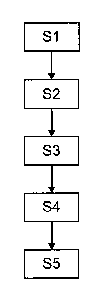
FIG. 4 illustrated the steps of a process according to the
invention.
As illustrated on FIG. 4, a process according to the invention
for determining position parameters defining the relative
position of a manufactured derivable surface relative to a
reference surface. Such process comprises:
¨ a nominal surface providing step S1,
¨ a measured surface providing step 52,
¨ a deformation surface providing step S3,
¨ a composed surface determining step S4, and
¨ a parameter determining step S5.
According to the embodiments describe hereafter, the
manufactured derivable surface is a surface of an optical lens.
However, the invention is not limited to such type of surface.
In particular, the manufactured surface may be a non-symmetric
derivable surface.
During the nominal surface providing step Sl, a nominal surface
expressed in a nominal frame of reference and corresponding to
the theoretical derivable surface to be manufactured with the
nominal value of the position parameters defining the relative
position of the nominal surface relative to the reference
surface is provided.
The positioning parameters may comprise at least six
parameters, for example three translation coefficients along
the axis of the nominal frame and three rotation coefficients
around the axis of the nominal frame.
CA 2833088 2017-05-11
14
In the measured surface providing step S2, a measured surface
of the manufactured derivable surface expressed in the nominal
frame of reference is provided.
For example, after the manufactured derivable surface is
manufactured, it is measured using optical measurements and
said measured surface is expressed in the same nominal frame of
reference as the nominal surface provided in the nominal
surface providing step Sl.
The process according to the invention comprise a deformation
surface providing step S3 during which at least one deformation
surface defined by at least one deformation parameter is
provided.
According to an embodiment of the invention, one of the
deformation surface may be a sphero-torus surface defined by a
sphere parameter, a cylinder parameter and an axis parameter.
According to an embodiment of the invention, one of the
deformation surface may correspond to a right circular cone
defined by an axis parameter and an angle parameter.
The deformation surface providing step of the process according
to the invention may comprise providing a plurality of
deformation surfaces.
Indeed, the inventors have observed that it is possible to link
the coefficient defining the deformation surface and some
manufacturing parameters of the manufacturing process.
Therefore, it may be interesting to provide as many deformation
surfaces as possible in order to be able to control as many
manufacturing parameters as possible.
CA2133308820171
5 According to the process of the invention, after having
provided the deformation surfaces, the process further
comprises a composed surface step S4 during which a composed
surface is determined by adding the measured surface and all
the different deformation surfaces.
10 During the parameters determining step S5, the position
parameters defining the position of the measured surface
relative to the reference surface in the nominal frame of
reference and the defoLmation parameters defining the different
deformation of the different deformation surfaces are
15 determined.
According to an embodiment of the invention, the parameters are
determined during the parameters determining step S5 by
minimizing the difference between the nominal surface and the
composed surface.
According to an embodiment of the invention, the parameters
determining step S5 further comprises a zone determining step
in which a zone of interest is determined in the nominal
surface and the position and deformation parameters are
determined by minimizing as much as possible the difference
between the nominal surface and the composed surface in the
zone of interest.
According to an embodiment of the invention, the parameters
determining step S5 is implemented by using a damped least
squares process.
The invention also relates to a method for controlling a
manufacturing process for example a lens manufacturing process.
CA2133820171
16
As illustrated in FIG. 5, a lens manufacturing process using a
manufacturing device comprises the steps of providing 10 a lens
blank, blocking 12 the lens blank using a blocking device,
machining 14 one surface of the lens blank using a machining
device, for example a generator or 3D coarse grinding machining
device and polishing 16 the machined surface of the lens using
a polisher.
The manufacturing steps 10 to 16 are repeated n times. After n
repetitions of the manufacturing steps a controlling process
according to the invention is processed.
The manufacturing process according the invention can be used
to manufacture any type of lens, for example ophthalmic lens
such as for example progressive additional lens.
The lens blank provided during the providing step 10 can be a
semi-finished lens blank.
The blocking step can be processed using any blocking devices
known from the man skilled in the art; such a device is
disclosed for example in patent documents U.S. Pat. No.
4,229,911 or 2006/031687.
The manufacturing step 14 consists in generating a desired
design on the unfinished surface of the lens. Generators are
common devices known from the man skilled in the art;
such a device is disclosed for example in patent documents EP 0
849 038 or US 2005/0188516.
The polishing step 16 consists in smoothing the manufactured
surface. Polishing devices are well known in the art.
CA2133820171
17
Once the manufacturing parameters have been properly calibrated
using for example a qualification process as disclosed in EP 08
853 275, lenses can be manufactured using the manufacturing
process according to the invention.
Such a manufacturing process can be controlled by a controlling
process according to the invention as illustrated on FIG. 6,
and comprising the steps of:
a) manufacturing a master lens 20
according to a
manufacturing process using a manufacturing device,
b) determining by the process according to the invention at
least one deformation parameter of the mater lens 22 of
step a),
c) recording the value of said deformation parameter 24,
d) repeating regularly step a) to c) and checking 28 the
evolution of said deformation parameter over time.
According to an embodiment of the invention, the master lenses
can be manufactured several times per day or be manufactured on
a regular basis not every day.
According to an embodiment of the invention the master lens has
a different geometrical and/or optical parameter and/or is made
of a different material than the lenses to be manufactured
during the manufacturing process.
The choice of the master lens can be done so as to amplify the
sensibility of certain parameter to the process parameters. For
example, the master lens is made of a material and has a design
such as its optical parameters are more sensitive to a
modification of the process parameter that the usual
manufactured lenses.
CA 2833088 2017-05-11
18
Examples of master lens design are given in EP 08 853 275.
The inventors have observed a correlation between the
deformation parameters that can be determined using the method
according to the invention and the manufacturing parameters.
For example, the inventors have observed a correlation between
the sphere, cylinder and axis parameters of the sphero-torus
deformation surface and the way the optical lens is blocked
during the manufacturing device.
Therefore, by determining the sphere, cylinder and axis
parameters using the process according to the invention on
master lens manufactured regularly, it is possible to detect a
defect in the blocking step.
The inventors have also observed that when the deformation
surface corresponds to a right circular cone defined by an axis
parameter and an angle parameter, said parameters can be
correlated to the positioning of the grinding tool during the
manufacturing process.
Therefore, the process according to the invention allows not
only to detect a defect in the manufacturing process but also
thanks to the determination of the deformation parameters to
identifies where in the manufacturing process a defect is
starting to appear.