Note: Descriptions are shown in the official language in which they were submitted.
CA 02833381 2013-10-16
WO 2012/145381 PCT/US2012/034048
Atty. Dkt. No. MLCZ 2 00171wOoi
Patent Application for
MOLD PUMP ASSEMBLY
BACKGROUND
[0001] The present exemplary embodiment relates to a pump assembly to pump
molten metal. It finds particular application in conjunction with a shaft and
impeller
assembly for variable pressure pumps for filling molds with molten metal, and
will be
described with particular reference thereto. However, it is to be appreciated
that the
present exemplary embodiment is also amenable to other like applications.
[0002] At times it is necessary to move metals in their liquid or molten
form. Molten
metal pumps are utilized to transfer or recirculate molten metal through a
system of
pipes or within a storage vessel. These pumps generally include a motor
supported by a
base member having a rotatable elongated shaft extending into a body of molten
metal
to rotate an impeller. The base member is submerged in the molten metal and
includes
a housing or pump chamber having the impeller located therein. The motor is
supported
by a platform that is rigidly attached to a plurality of structural posts or a
central support
tube that is attached to the base member. The plurality of structural posts
and the
rotatable elongated shaft extends from the motor and into the pump chamber
submerged in the molten metal within which the impeller is rotated. Rotation
of the
impeller therein causes a directed flow of molten metal.
[0003] The impeller is mounted within the chamber in the base member and is
supported by bearing rings to act as a wear resistant surface and allow smooth
rotation
therein. Additionally, a radial bearing surface can be provided on the
elongated shaft or
impeller to prevent excessive vibration of the pump assembly which could lead
to
inefficiency or even failure of pump components. These pumps have
traditionally been
referred to as centrifugal pumps.
[0004] Although centrifugal pumps operate satisfactorily to pump molten
metal, they
have never found acceptance as a means to fill molten metal molds. Rather,
this task
has been left to electromagnetic pumps, pressurized furnaces and ladeling.
Known
centrifugal pumps generally control a flow rate and pressure of molten metal
by
1
CA 02833381 2013-10-16
WO 2012/145381 PCT/US2012/034048
Atty. Dkt. No. MLCZ 2 00171USP1
modulating the rotational rate of the impeller. However, this control
mechanism
experiences erratic control of the flow rate and pressure of molten metal when
attempting to transfer molten metal into a mold such as a form mold. The
erratic control
of the flow of molten metal into the form mold is especially prevalent when
attempting to
fill a form mold for a complicated or intricately formed tool or part.
BRIEF DESCRIPTION
[0005] In one embodiment, the present disclosure relates to a molten metal
pump
assembly to fill molds with molten metal. The pump assembly comprises an
elongated
shaft connecting a motor to an impeller. The impeller is housed within a pump
chamber
of a base member such that rotation of the impeller draws molten metal into
the
chamber at an inlet and forces molten metal through an outlet of the chamber.
The
impeller includes a first radial edge spaced from a second radial edge such
that the first
radial edge is adjacent the elongated shaft. A bearing assembly surrounds the
impeller
within the chamber, the bearing assembly includes a first bearing adapted to
support
the rotation of the impeller at the first radial edge and a second bearing
adapted to
support the rotation of the impeller at the second radial edge. At least one
bypass gap is
interposed between one of the first and second bearings and the associated
first and
second radial edges. The bypass gap is operative to manipulate a flow rate and
a head
pressure of the molten metal. Molten metal leaks from the chamber through the
bypass
gap at a predetermined rate as the impeller is rotated such that a precise
control of the
flow rate is achieved.
[0006] In another embodiment of the present disclosure, a method of filling
a mold
with molten metal is provided. The method comprises rotating an impeller
within a
chamber. Molten metal is transferred through the impeller into the chamber. A
predetermined portion of molten metal leaks through at least one bypass gap
from the
chamber to the base exterior. The leakage rate allows for precise tuning of a
head
pressure relative to a rotational speed of the impeller. An associated mold is
filled with
the molten metal and is controlled by a programmable control profile.
[0007] According to yet another embodiment of the present disclosure, a molten
metal pump assembly to fill molds with molten metal is provided. The pump
assembly
2
comprises an elongated shaft connecting a motor to an impeller. The impeller
is
housed within a chamber of a base member such that rotation of the impeller
draws
molten metal into the chamber at an inlet and forces molten metal through an
outlet
of the chamber. The impeller includes a first radial edge adjacent to a first
peripheral
circumference spaced from a second radial edge adjacent to a second peripheral
circumference such that the elongated shaft is rigidly attached to the first
peripheral
circumference.
[0008] A bearing
assembly surrounds the impeller within the chamber and
includes a first bearing adapted to support the rotation of the impeller at
the first
radial edge and a second hearing adapted to support the rotation of the
impeller at
the second radial edge. At least one bypass gap is provided at the second
peripheral
circumference to provide fluid communication between the chamber and a
surrounding environment. The bypass gap is operative to allow a predetermined
amount of molten metal leak from the chamber such that precise control of the
flow
rate and head pressure of the molten metal is provided at the outlet.
[0008a] According
to yet another embodiment of the present disclosure, a
molten metal pump assembly to fill a mold with molten metal is disclosed, the
pump
assembly comprising an elongated shaft connecting a motor to an impeller, the
impeller being housed within a chamber of a base member such that rotation of
the
impeller draws molten metal into the chamber at an inlet and forces molten
metal
through an outlet of the chamber, the impeller including a first radial edge
spaced
from a second radial edge such that the first radial edge is proximate the
elongated
shaft; and a bearing assembly surrounding the impeller within the chamber, the
bearing assembly including: a first bearing opposing the first radial edge; a
second
bearing opposing the second radial edge; and at least one bypass gap
interposed
between a portion of one of the first and second bearings and the associated
first and
second radial edges, a lubrication gap interposed between the other of the
first and
second bearings and the associated first and second radial edges, the bypass
gap
having a width greater than a width of the lubrication gap, said lubrication
gap being
configured such that the bearing supports rotation of the impeller, the bypass
gap
communicating between the chamber and an environment external to the pump
assembly to leak molten metal from the pump assembly during operation and
modify
a flow rate and a head pressure of the molten metal as the molten metal exits
the
outlet of the chamber.
[0008b] According
to yet another embodiment of the present disclosure, a
molten metal pump assembly to fill molds with molten metal is disclosed, the
pump
3
CA 2833381 2019-04-02
assembly comprising an elongated shaft connecting a motor to an impeller, the
impeller is housed within a chamber of a base member such that rotation of the
impeller draws molten metal into the chamber at an inlet and forces molten
metal
through an outlet of the chamber, the impeller including a first radial edge
adjacent to
a first peripheral circumference .spaced from a second radial edge adjacent to
a
second peripheral circumference such that the elongated shaft is rigidly
attached to
the first peripheral circumference; and a bearing assembly surrounding the
impeller
within the chamber, the bearing assembly including: a first bearing pair
adapted to
support the rotation of the impeller at the first radial edge, one bearing of
said pair
mounted on said impeller and one bearing of said pair mounted on said chamber;
a
second bearing pair adapted to .support the rotation of the impeller at the
second
radial edge, one bearing of said pair mounted on said impeller and one bearing
of
said pair mounted on said chamber; and at least one bypass gap is provided at
the
second peripheral circumference to communicate between the chamber and an
external environment, the bypass gap comprising a space between the bearing
pair
which is greater than a space between the other bearing pair, the bypass gap
communicating between the chamber and an environment external to the pump
assembly to leak molten metal from the pump assembly during operation and
modify
a flow rate and head pressure of the molten metal as the molten metal exits
the outlet
of the chamber.
[0009] One aspect of the present disclosure is an assembly and method of
use
for a molten metal pump to fill complex molds such that the bypass gap allows
for a
more precise flow control.
BRIEF DESCRIPTION OF THE DRAWINGS
[0010] FIGURE 1 is a front view of a prior art molten metal pump
assembly;
[0011] FIGURE 2 is a cross sectional view of a portion of the molten
metal pump
assembly, the portion including an elongated shaft attached to an impeller
within a
chamber of a base member;
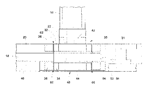
[0012] FIGURE 3 is a perspective view of the elongated shaft and the
impeller;
[0013] FIGURE 4 is an end view of the impeller;
[0014] FIGURE 5 is a front view of the elongated shaft;
[0015] FIGURE 6 is a cross sectional view of the base member;
[0016] FIGURE 7 is an exploded cross sectional view of the elongated
shaft
attached to the impeller within the chamber of the base member illustrated in
FIGURE 2;
3a
CA 2833381 2019-04-02
CA 02833381 2013-10-16
WO 2012/145381 PCT/US2012/034048
Atty. Dkt. No. MLCZ 2 00171USP1
[0017] FIGURE 8 is a graph indicating the relationship between molten metal
pressure at an outlet and a molten metal flow rate relative to the rotations
per minute
(RPM) of the impeller of the pump assembly;
[0018] FIGURE 9 is a graph indicating an exemplary relationship between RPM
and
time related to a programmable mold fill profile;
[0019] FIGURE 10 is a graph of an exemplary programmable mold fill profile
associated with a complicated mold.
DETAILED DESCRIPTION
[0020] It is to be understood that the detailed figures are for purposes of
illustrating
the exemplary embodiments only and are not intended to be limiting.
Additionally, it will
be appreciated that the drawings are not to scale and that portions of certain
elements
may be exaggerated for the purpose of clarity and ease of illustration.
[0021] With reference to FIGURE 1, an example of a molten metal pump assembly
submerged in a bath of molten metal 12 is displayed. The molten metal 12, such
as
aluminum, can be located within a furnace or tank (not shown). The molten
metal pump
assembly 10 includes a motor 14 connected to an elongated shaft 16 via
coupling 17.
The motor is adapted to be run at variable speed by a programmable controller
19, such
as a computer or other processor. The elongated shaft 16 is connected to an
impeller
22 located in the chamber 18 of a base member 20. The base member 20 is
suspended
by a plurality of refractory posts 24 attached to a motor mount 26. An
alternative form of
post could also be employed wherein a steel rod surrounded by a refractory
sheath
extends between the motor mount and the base member 20.
[0022] The elongated shaft 16 is rotated by the motor 14 and extends from the
motor
14 and into the pump chamber 18 submerged in the molten metal 12 within which
the
impeller 22 is rotated. Rotation of the impeller 22 therein causes a directed
flow of
molten metal 12 through an associated metal delivery conduit (not shown) such
as a
riser, adapted for fluid metal flow. The riser for the metal delivery conduit
system is
connected to the outlet of the pump chamber 18 which is typically adjacent a
side wall
or top wall of the base member. These types of pumps are often referred to as
transfer
4
1,
pumps. An example of one suitable transfer pump is shown in U.S. Patent
5,947,705.
[0023] With reference to FIGURES 2-6, elements of the molten
metal pump
assembly 10 of the present disclosure are illustrated. More particularly, the
elongated
shaft 16 has a cylindrical shape having a rotational axis that is generally
perpendicular to the base member 20. The elongated shaft has a proximal end 28
that is adapted to attach to the motor 14 by the coupling 17 and a distal end
30 that is
connected to the impeller 22. The impeller 22 is rotably positioned within the
pump
chamber 18 such that operation of the motor 14 rotates the elongated shaft 16
which
rotates the impeller 22 within the pump chamber 18.
[0024] The base member 20 defines the pump chamber 18 that
receives the
impeller 22. The base member 20 is configured to structurally receive the
refractory
posts 24 (optionally comprised of an elongated metal rod within a protective
refractory sheath) within passages 31. Each passage 31 is adapted to receive
the
metal rod component of the refractory post 24 to rigidly attach to a motor
mount 26.
The motor mount 26 supports the motor 14 above the molten metal 12.
[0025] In one embodiment, the impeller 22 is configured with a
first radial edge
32 that is axially spaced from a second radial edge 34. The first and second
radial
edges 32, 34 are located peripherally about the circumference of the impeller
22. The
pump chamber 18 includes a bearing assembly 35 having a first bearing ring 36
axially spaced from a second bearing ring 38. The first radial edge 32 is
facially
aligned with the first bearing ring 36 and the second radial edge 34 is
facially aligned
with the second bearing ring 38. The bearing rings are made of a material,
such as
silicon carbide, having frictional bearing properties at high temperatures to
prevent
cyclic failure due to high frictional forces. The bearings are adapted to
support the
rotation of the impeller 22 within the base member such that the pump assembly
10
is at least substantially prevented from vibrating. The radial edges of the
impeller
may similarly be comprised of a material such as silicon carbide. For example,
the
radial edges of the impeller 22 may be comprised of a silicon carbide bearing
ring.
[0026] In one embodiment, the impeller 22 includes a first
peripheral
circumference 42 axially spaced from a second peripheral circumference 44. The
elongated shaft 16 is
CA 2833381 2018-08-20
attached to the impeller 22 at the first peripheral circumference 42. The
second
peripheral circumference 44 is spaced opposite from the first peripheral
circumference
44 and aligned with a bottom portion 46 of the base member 20. The first
radial edge
32 is adjacent to the first peripheral circumference 42 and the second radial
edge 34
is adjacent to the second peripheral circumference 44.
[0027] In one
embodiment, a bottom inlet 48 is provided in the second peripheral
circumference 44. More particularly, the inlet comprises the annulus of a bird
cage
style of impeller 22. Of course, the inlet can be formed of vanes, bores,
annulus ("bird
cage") or other assemblies known in the art. It is noted that a top feed pump
assembly
or a combination top and bottom feed pump assembly may also be used.
[0028] As will be
apparent from the following discussion, a bored or bird cage
impeller may be advantageous because they include a defined radial edge
allowing a
designed tolerance (or bypass gap) to be created with the pump chamber 18. An
example of a bored impeller is provided by U.S. Patent 6,464,458.
[0029] The
rotation of the impeller 22 draws molten metal 12 into the inlet 48 and
into the chamber 18 such that continued rotation of the impeller 22 causes
molten
metal 12 to be forced out of the pump chamber 18 to an outlet 50 of the base
member
20.
[0030] With reference to FIGURE 6, the bearing assembly 35 includes a base
ring
bearing adapter 52 that is configured to connect the second bearing ring 38 to
the
bottom portion 46 of the base member 20. The base ring bearing adapter 52
includes
a radial flange portion 54 that is rigidly attached to a disk body 56 and is
operative to
support bearing rings of various sizes along the bottom portion 46 of the base
member
20. The radial flange portion 54 is adjacent the pump chamber 18 and is
generally
perpendicular to the disk body 56.
[0031] FIGURE 7
illustrates the impeller 22 located within the base member 20. A
close tolerance is maintained between radial edge 32 of the impeller 22 and
the first
bearing ring 36 to provide rotational and structural support to the impeller
22 within the
chamber 18. The base ring bearing adapter 52 is generally circular and is
configured
for receiving the second bearing ring 38. Base ring bearing adapter 52 and
bearing
rings of different sizes can be provided at the base member to interact with
the impeller
6
CA 2833381 2019-04-02
CA 02833381 2013-10-16
WO 2012/145381 PCT/US2012/034048
Ally. Dkt. No. MLCZ 2 00171USP1
22 such that a bypass gap 60 of a desired size is provided between the bearing
ring 38
and the radial edge 34 of impeller 22. Optionally, it is contemplated that the
bypass gap
60 may be provided between the first radial edge 32 and the first bearing ring
36.
[0032] In one embodiment, the bypass gap 60 is interposed between a portion
of the
second bearing ring 38 and the second radial edge 34. For example, the bypass
gap
60 is a radial space interposed between at least a portion of the second
bearing 38 and
the second radial edge 34 of the impeller 22. The radial space is of a
designed
tolerance that can be varied to allow for a predetermined leakage rate of the
molten
metal 12.
[0033] In this regard, it is noted that a lubrication gap 62 exists between
the radial
edge 32 of the impeller 22 and the bearing ring 36 disposed within the base
20. The
lubrication gap is a space provided within which molten metal is retained to
provide a
low friction boundary. The lubrication gap can vary based upon the
constituents of the
relevant alloy. It is contemplated that the bypass gap will have a width (i.e.
a distance
between the impeller and the base) of at least about 1.25x the lubrication
gap, or
between about 1.5 and 6x the lubrication gap, or between about 2 and 4x the
lubrication
gap or any combination of such ranges.
[0034] It is also noted that a discontinuous gap width may be employed
wherein
relatively close tolerance regions are interspersed with relatively large
bypass gap width
regions.
[0035] For example, the bypass gap 60 may be a plurality of removable
segmented
teeth or posts that are radially positioned about the perimeter of the
impeller 22 such
that a plurality of teeth maintain contact with bearing ring 38 during
rotation of the
impeller 22 while radial spaces interposed between the teeth are configured to
allow
leakage of the molten metal 12 at a predetermined rate. In another embodiment,
the
bypass gap 60 may be provided by a plurality of apertures located through the
first
peripheral circumference 42 of the impeller to 22 allow fluid communication
with the
chamber 18 and an environment outside the base member. Further, it is
contemplated
that at least one bypass gap can also be provided downstream of the impeller
22 within
the pump chamber 18 adjacent to outlet 50 or can even be located within the
riser. This
type of bypass gap can be comprised of a hole(s) drilled into a pump assembly
7
CA 02833381 2013-10-16
WO 2012/145381 PCT/US2012/034048
Atty. Dkt. No. MLCZ 2 00171USP1
component. In short, it is feasible to provide a molten metal pump that is
functional in
filling complex molds by providing a designed leakage path at any point in the
pump
assembly.
[0036] The bypass gap 60 is operative to manipulate a flow rate and a head
pressure of the molten metal 12. The bypass gap 60 allows molten metal to leak
from
the pump chamber 18 to an environment outside of the base member 20 at a
predetermined rate. The leakage of molten metal 12 from the pump chamber 18
during
the operation of the pump assembly 10 allows an associated user to finely tune
the flow
rate or volumetric amount of molten metal 12 provided to an associated mold.
The
leakage rate of molten metal 12 through the bypass gap 60 improves the
controllability
of the transport of molten metal 12 and is at least in part, due to a
viscosity coefficient of
the molten metal 12. Namely, in one embodiment, as the viscosity of the molten
metal
12 decreases, a size of the bypass gap 60 would also be decreased to get the
optimal
leakage rate of molten metal 12.
[0037] In one embodiment, the bypass gap 60 is provided by the second
bearing ring
38 such that the second bearing ring 38 includes a larger inner diameter than
the first
bearing ring 36 in the bearing assembly 35. In this regard, there is a greater
space
between said radial edge 34 and second bearing ring 38. In another embodiment,
the
bypass gap 60 is provided by the impeller 22 such that the second radial edge
34 of the
impeller 22 has a smaller diameter than the first radial edge 32. Here, the
first radial
edge 32 is abuttingly positioned and rotably supported at the first bearing
ring 36 within
the pump chamber 18 to form the relatively narrower lubrication gap while a
bypass gap
exists between the second bearing ring 38 and the second radial edge 34. Of
course, a
top side gap can be created by reversing the dimensions disclosed above.
[0038] In one embodiment, the pump assembly includes an ability to
statically
position molten metal 12 pumped through the outlet 50 and into a riser at
approximately
1.5 feet of head pressure above a body of molten metal 12. In one embodiment
the
impeller rotates approximately 850-1000 rotations per minute such that molten
metal is
statically held at approximately 1.5 feet above the body of molten metal 12.
The bypass
gap 60 manipulates the volumetric flow rate and head pressure relationship of
the pump
such that an increased amount of rotations per minute of the impeller 22 would
allow
8
CA 02833381 2013-10-16
WO 2012/145381 PCT/US2012/034048
Atty. Dkt. No. MLCZ 2 00171USP1
the reduction of head pressure as the flow rate of molten metal 12 is
increased. This
relationship as schematically illustrated by the graph in FIGURE 8.
[0039] Precise control to the amount of molten metal 12 provided to an
associated
mold is achieved by positioning the bypass gap 60 between the bearing assembly
35
and the impeller 22. More particularly, in one embodiment, the motor 14 is
operated by
a programmable command rpm profile as illustrated by FIGURE 9. A command RPM
profile is programmed into a controller to electrically communicate with the
motor to
rotate the impeller and force molten metal through the outlet 50 and into the
metal
delivery conduit such that the outlet of the metal delivery conduit is adapted
to an
associated mold. The programmable command RPM profile varies a signal to the
motor
in relation to the volumetric fill rate and geometry of the associated mold.
[0040] With reference to FIGURE 10, in one embodiment, an associated mold (not
shown) includes a generally complex geometric area or riser to be filled by
molten metal
12 such as aluminum. The metal delivery conduit or riser (not shown) is
adapted to fill
the associated mold with aluminum from the pump assembly 10. The pump assembly
is programmed with a command RPM profile, as illustrated in FIGURE 10, that is
associated with the inner geometric volume of the associated mold. This
profile controls
a command voltage at the motor 14 to rotate the impeller 12 at a predetermined
rotational rate to fill the associated mold in accordance with form mold
limits 1 - 5 at
predetermined times. More particularly, the bypass gap 60 allows an increase
in the
magnitude of command RPM required to provide the necessary head pressure of
molten metal 12 to the associated mold. This assembly and method is
advantageous
when filling associated molds to form complex parts within molds with a
complicated
geometric arrangement as finer tuning of an amount of molten metal 12 provided
by the
pump assembly 10 is achieved. Examples of molded parts suitable for casting
using
the pump assembly disclosed herein include, but are not limited to, engine
blocks,
wheels and cylinder heads.
[0041] The exemplary embodiment has been described with reference to the
preferred embodiments. Obviously, modifications and alterations will occur to
others
upon reading and understanding the preceding detailed description. It is
intended that
the exemplary embodiment be construed as including all such modifications and
9
CA 02833381 2013-10-16
WO 2012/145381 PCT/US2012/034048
Atty. Dkt, No. MLCZ 2 00171USP1
alterations insofar as they come within the scope of the appended claims or
the
equivalents thereof.