Note: Descriptions are shown in the official language in which they were submitted.
CA 02833504 2013-11-19
TUBE TYPE BIRD FEEDER
FIELD OF THE INVENTION
The present invention relates to bird feeders and more particularly, relates
to
improvements in a tube type bird feeder.
BACKGROUND OF THE INVENTION
Tube type bird feeders are well known in the art. They basically comprise a
seed
retaining container of a tubular configuration which is usually transparent in
nature. A base
seals the bottom while a cover is provided. The cover can be removed so as to
provide
access to the seed container for filling of the same. Normally, one or more
perches are
provided proximate the one or more seed access openings in the seed container.
Most tube bird feeders are designed to be as inexpensive as possible. They are
conventionally manufactured in a manner so as to not encourage disassembly of
the same.
However, in so doing, this can cause problems. One of the problems associated
with all
types of bird feeders is cleanliness. Unless a proper design is provided, the
seed will, over a
period of time, become mouldy. It is also subject to contamination by bird
droppings.
Without proper care, this can lead to illness among the bird population using
the feeder.
A further problem associated with tube bird feeders pertains to ventilation of
the seed
retaining container. Due to the nature of bird feeders, most are exposed to
weather and as a
consequence, moisture frequently reaches the inside of the seed retaining
container. This
can cause problems for the seeds which remain therein as mold is a persistent
problem.
SUMMARY OF THE INVENTION
It is an object of the present invention to provide an improved tube type bird
feeder
wherein the components of the bird feeder can easily be disassembled and
assembled.
It is a further object of the present invention to provide for ventilation of
the tube type
- 1 -
CA 02833504 2013-11-19
=
bird feeder.
According to one aspect of the invention, there is a provided a bird feeder
comprising
a seed tube having a side wall, at least one feed opening in the side wall,
the side wall
having a top marginal edge and a bottom marginal edge, a cover removably
engaged with
the seed tube proximate the top marginal edge, at least one perch mounted on
the seed tube
proximate the feed opening, and a base member removably secured to the seed
tube adjacent
the bottom marginal edge.
A traditional tube bird feeder comprises a hollow tube having feed access
openings
therein. Perches are usually at least one rod which passes through the tube
and extends
outwardly. They are secured in position by mechanical means. A base prevents
the seed
from exiting and it is also usually secured in place by mechanical fasteners.
The cover
arrangement will again usually comprise a wire member which will engage with
the hollow
tube either directly or indirectly. The cover slides on the wire member and
access to the
tube is gained by tilting the wire member to the side while the cover is
elevated.
The conventional tube bird feeder is not easily disassembled and tools are
usually
required. The bird feeder of the instant invention overcomes many of the
disadvantages of
the known tube bird feeder and can be assembled and disassembled without the
use of tools.
In greater detail, the bird feeder of the present invention may utilize a
conventional
seed tube with an open top and an open bottom. Conventionally, the seed tubes
are formed
of a plastic material and are transparent although other materials can be
utilized.
The seed tube is provided with at least one feed access opening and in a
preferred
embodiment, has two seed access openings which are diametrically opposed. Each
seed
access opening preferably has a perch mounted proximate thereto to enable a
bird to perch
while feeding.
- 2 -
CA 02833504 2013-11-19
The bird feeder will also have a cover which is designed to seal the open top
end.
The cover is preferably removable and retained such that access may be had to
the interior of
the tube for filling of the same. Most covers utilized for tube feeders are
held in a non
rotatable manner. In a preferred embodiment, the bail holding the bird feeder
through the
cover is mounted such that the bird feeder can rotate about the bail.
The base member is removably secured to the seed tube adjacent a bottom
marginal
edge of the tube. In a preferred embodiment, the base member has a protrusion
which will
engage with an aperture formed in the seed tube proximate the aforementioned
bottom
marginal edge.
The base member is preferably formed of an upper base portion and a lower base
portion. They are retained together in a non rotatable manner. The upper base
portion will
include a pair of half walls defining the top thereof and upon which the seed
in the seed tube
will be supported. Preferably the two half walls have apertures therein to
permit drainage
and ventilation.
The locking of the base member to the seed tube by the protrusion can rely on
the
flexibility of the seed tube or alternatively, the base member may be designed
to have a
certain flexibility. The protrusion is such that the seed tube can fit within
and be slidable
thereover due to the shape of the front or face wall of the protrusion as will
be described in
greater detail hereinbelow.
The cover is releasably secured directly to the tube. The cover will include
at least
one protrusion which will engage with an aperture formed in the seed tube
proximate an
upper marginal edge of the seed tube. Due to the shape of the protrusion, as
will be
described hereinbelow, removal of the cover is easily achieved while it is
securely attached
to the seed tube during normal use.
- 3 -
CA 02833504 2013-11-19
The cover will include ventilation apertures formed therein, the ventilation
apertures
being formed in a manner that rain and the like cannot easily access the
ventilation
apertures.
BRIEF DESCRIPTION OF THE DRAWINGS
Having thus generally described the invention, reference will be made to the
accompanying drawings illustrating an embodiment thereof, in which:
Figure 1 is a perspective view of a bird feeder according to the present
invention;
Figure 2 is a longitudinal sectional view thereof;
Figure 3 is a longitudinal sectional view with the bird feeder rotated 1800
from the
view of Figure 2;
Figure 4 is a cross-sectional view illustrating the upper portion of the bird
feeder;
Figure 5 is a cross-sectional view illustrating the bottom portion of the bird
feeder;
Figure 6 is an exploded view of the cover and bail;
Figure 7 is a bottom view of the cover with the bail connected thereto;
Figure 8 is an exploded perspective view of the tube container and bottom
portion;
Figure 9 is a perspective view from the bottom of the exploded view of Figure
8;
Figure 10 is a detailed cross-sectional view of the bottom or base portion of
the bird
feeder; and
Figure 11 is a perspective view illustrating insertion of a perch and
associated
structure.
DETAILED DESCRIPTION OF THE INVENTION
Referring to the drawings in greater detail and by reference characters
thereto, there
is illustrated a bird feeder which is generally designated by reference
numeral 10.
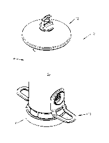
Bird feeder 10 comprises four different components ¨ a cover generally
designated
- 4 -
CA 02833504 2013-11-19
by reference numeral 12, a seed container generally designated by reference
numeral 14, a
base structure generally designated by reference numeral 16, and a perch
structure generally
designated by reference numeral 18.
Cover 12 is formed with a domed top wall 22 and a downwardly extending
cylindrical side wall 24. It will be noted that cylindrical side wall 24 is
spaced inwardly of
domed top wall 22. Domed top wall 22 terminates with an outer downwardly
extending
flange 26.
Domed top wall 22 is also provided with upwardly extending protrusions 28
which
have spaces 34 therebetween. Located centrally of domed top wall 22 is a
central aperture 30.
Venting apertures 32 are provided proximate central aperture 30. On the inner
surface of
domed top wall 22, there is provided a plurality of downwardly extending tabs
31.
A bail generally designated by reference numeral 36 includes an inverted U-
shaped
portion 38 for hanging from a hook or the like. A leg 40 extends downwardly;
leg 40 has an
expanded end 42 which provides a seating wall or ledge 44. The arrangement is
such that
leg 40 passes through central aperture 30 and seating wall 44 engages with
tabs 31 to retain
the bail secured to the cover. Bail 36 also includes a horizontal wall 37
which engages with
upwardly extending protrusions 28 such that spaces 34 provide air
communication with
venting apertures 32 to thereby permit air exchange between seed container 14
and the
exterior
The inner surface of cylindrical side wall 24 includes a pair of protrusions
46 each
having a front face 48 which tapers upwardly and outwardly from the point
where it merges
with the surface of side wall 24. At its upper portion, there is provided a
top wall 50 for
engaging seed container 14 as will be discussed in greater detail hereinbelow.
Seed container 14 is defined by a tubular side wall 54 which is preferably
formed of a
- 5 -
CA 02833504 2013-11-19
transparent flexible plastic material. A pair of seed access openings 56 and
58 are provided
and preferably they are diametrically opposed for aesthetic reasons. A first
set of upper
apertures 60, 62 are provided near the top marginal edge of tubular side wall
54 while a
second pair of upper apertures 64, 66 are spaced therefrom and a little bit
lower. Proximate
the lower marginal edge, there are provided diametrically opposed lower
apertures 68, 70.
Base structure 16 includes a seed support wall 74 upon which the seed rests
and is
directed outwardly proximate seed openings 56, 58. Drainage apertures 76 are
provided in
wall 74.
Base structure 16 also includes an upper side wall 78 and a lower side wall
80.
Extending between the top of lower side wall 80 and the base of upper side
wall 78 is a
horizontal wall section 81. It will be noted that upper side wall 78 includes
a pair of tab
members 82, 84 which provide some flexibility to that portion of upper side
wall 78.
Mounted on the inner surface of tabs 82, 84 are protrusions 86. Each
protrusion 86 has a
tapering front wall 88 for reasons which will become apparent hereinbelow.
Tapering front
wall 88 terminates in a bottom wall 89 which forms a stop for engaging with
seed
container 14 as will be discussed in greater detail hereinbelow.
As may be seen in Figure 9, base structure 16 also includes a plurality of
ribs 96
extending between center wall 90 and lower side wall 80. Mounted at the outer
end of
ribs 96 are stoppers 100 which support seed tube 14.
At its lower end, base structure 16 is provided with a center wall 90 which
defines a
recess 92 for receiving a post which supports the bird feeder. Located within
recess 92 is a
circular structure 94. This arrangement is such that recess 92 can accommodate
either of the
commonly sized poles. Thus, a larger post will be retained by center wall 90.
Alternatively,
a smaller post may have a size such that it will fit about circular structure
94.
- 6 -
CA 02833504 2013-11-19
The bird feeder preferably includes a perch structure as shown. As may be best
seen
in Figure 11, seed access openings 56 and 58 are similar and thus, only one
will be described
herein. Formed at the top and bottom portions of seed access opening 56 are a
pair of
smaller recesses 104. Perch structure 18 includes a baffle 106 which has a
pair of
protrusions 108 extending outwardly therefrom. Perch structure 18 also
includes an upper
plate 110 which fits about feed access opening 56 and a lower U-shaped perch
112.
For assembly, perch structure 18 is initially set in place by inserting the
baffle portion
to the interior whereby protrusions 108 will fit through recesses 104. The
perch structure 18
is then rotated to its proper position.
To assemble the structure, base structure 16 and the bottom of seed tube 14
may be
assembled such that the bottom of side wall 54 is inserted interiorly of upper
side wall 78.
The tapering front wall 88 permits the side wall to enter and seat on stoppers
100. A
rotational movement can be given until protrusions 86 seat in lower apertures
68, 70. The
base 16 is retained on seed tube 14 due to engagement with bottom wall 89.
It will be noted that the bottom of plate portion 110 is sized such that upper
side
wall 78 seats thereagainst.
Cover 12 may then be placed in position with protrusions 46 on cylindrical
side
wall 24 seating within upper apertures 60, 62.
The bird feeder 10 is provided with ventilation extending from the bottom up
through
the seed container with the upper ventilation being accomplished with
apertures 64, 66 and
the venting through venting apertures 32.
It will be understood that the above described embodiments are for purposes of
illustration only and that changes and modifications may be made thereto
without departing
from the spirit and scope of the invention.
- 7 -