Note: Descriptions are shown in the official language in which they were submitted.
CA 02833544 2013-10-17
WO 2012/145317 PCT/US2012/033937
APPARATUS AND METHOD FOR PANORAMIC VIDEO
IMAGING WITH MOBILE COMPUTING DEVICES
FIELD OF THE INVENTION
[0001] The present invention relates to an apparatus and method for panoramic
video
imaging.
BACKGROUND INFORMATION
[0002] Panoramic imaging systems including optical devices, unwarping
software,
displays and various applications are disclosed in U.S. Patent Nos. 6,963,355;
6,594,448;
7,058,239; 7,399,095; 7,139,440; 6,856,472; and 7,123,777 assigned to
Eyesee360, Inc. All
of these prior patents are incorporated herein by reference.
SUMMARY
[0003] In one aspect, the invention provides an apparatus including a housing,
a
concave panoramic reflector, a support structure configured to hold the
concave panoramic
reflector in a fixed position with respect to the housing, and a mounting
device for positioning
the housing in a fixed orientation with respect to a computing device such
that light reflected
by the concave panoramic reflector is directed to a light sensor in the
computing device.
[0004] In another aspect, the invention provides a method including: receiving
panoramic image data in a computing device, viewing a region of the panoramic
image in real
time, and changing the viewed region in response to user input and/or an
orientation of the
computing device.
[0005] In another aspect, the invention provides an apparatus including a
panoramic
optical device configured to reflect light to a camera, a computing device for
processing image data from the camera to produce rendered images, and a
display for
showing at least a portion of the rendered images, wherein the displayed
images are changed
in response to user input and/or an orientation of the computing device.
BRIEF DESCRIPTION OF DRAWINGS
[0006] FIGs. 1A, 1B and 1C illustrate a panoramic optical device.
[0007] FIGs. 2A, 2B and 2C illustrate a panoramic optical device.
- 1 -
CA 02833544 2013-10-17
WO 2012/145317 PCT/US2012/033937
[0008] FIGs. 3A, 3B, 3C, 3D, 3E and 3F illustrate a panoramic optical device.
[0009] FIGs. 4A, 4B and 4C illustrates a case attached to a mobile computing
device.
[0010] FIGs. 5A, 5B, 6A, 6B, 7A, 7B, 8A, 8B, 9A, 9B, 9C, 10A and 10B
illustrate
structures for mounting a panoramic optical device to a mobile computing
device such as an
iPhone.
[0011] FIGs. 11A, 11B, 11C, 11D and 11E illustrate another panoramic optical
device.
[0012] FIGs. 12A, 12B and 12C illustrate a case attached to a mobile computing
device.
[0013] FIGs. 13 and 14 illustrate panoramic mirror shapes.
[0014] FIGs. 15-17 are flow charts illustrating various aspects of certain
embodiments
of the invention.
[0015] FIGs. 18, 19A and 19B illustrate interactive display features in
accordance
with various embodiments of the invention.
[0016] FIGs. 20, 21 and 22 illustrate orientation based display features in
accordance
with various embodiments of the invention.
[0017] FIG. 23 is a flow chart illustrating another aspect of the invention.
DETAILED DESCRIPTION
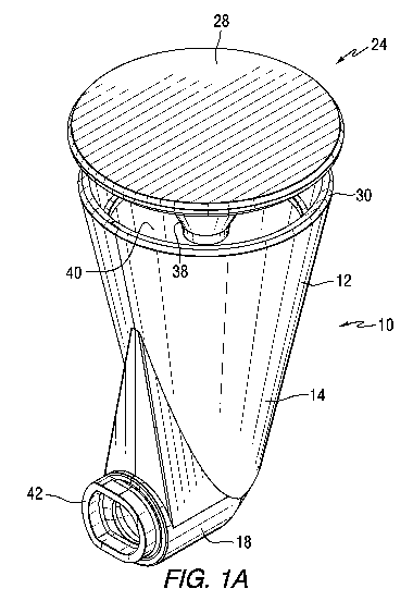
[0018] FIGs. 1A, 1B and 1C illustrate a panoramic optical device 10 (also
referred to
herein as an optic) for attachment to a computing device, in accordance with
an embodiment
of the invention.. In various embodiments, the computing device can be a
mobile computing
device such as an iPhone, or other phone that includes a camera. In other
embodiments, the
computing device can be a stationary or portable device that includes
components that have
signal processing capabilities needed to perform at least some of the
functions described
herein. The computing device may include a camera or other image sensor, or
may be
capable of receiving image data from a camera or other image sensor.
[0019] FIG. lA is an isometric view, FIG. 1B is a side view, and FIG. 1C is a
front
view of an embodiment of the optical device 10. The device includes a housing
12. In this
embodiment, the housing includes a first portion 14 having a first axis 16 and
a second
portion 18 having a second axis 20. For convenience, the first axis can be
referred to as a
vertical axis and the second axis can be referred to as a horizontal axis.
However the spatial
- 2 -
CA 02833544 2013-10-17
WO 2012/145317 PCT/US2012/033937
orientation of the axes will depend on the orientation of the device when in
use. At least a
part 22 of the first portion of the housing has a frustoconical shape. A
reflector assembly 24
is attached to the first portion of the housing and centered along a first
axis 16 of the housing.
The reflector assembly includes concave panoramic mirror 26 extending downward
from a
top portion 28. The panoramic mirror extends into the housing and beyond an
end 30 of the
housing to create a gap 32. Light entering the gap is reflected by the concave
panoramic
mirror 26 into the housing. A second mirror 34 is mounted within the housing
to direct the
light toward an opening 36. In one embodiment, the second mirror is a planar
mirror
positioned at a 45 angle with respect to both the first axis 16 and the
second axis 20. Light is
reflected off of the second mirror in a direction toward the opening 36 at an
end of the second
portion of the housing. The reflector assembly further includes a post 38
positioned along
axis 16 and coupled to a transparent support member 40. By mounting the
reflector assembly
in this manner, the use of other support structures (which could result in
glare) is avoided.
[0020] The housing 12 further includes a projection 42 extending from the
second
portion, and shaped to couple to a case or other mounting structure that is
used to couple the
optical device to a computing device and to hold the optical device in a fixed
orientation with
respect to the computing device. In the embodiment of FIGs. 1A, 1B and 1C the
projection
has an oblong shape with two elongated sides 44, 46 and two arcuate ends 48
and 50. In this
embodiment, the radius of curvature of end 48 is smaller than the radius of
curvature of end
50. This prevents the end 50 from extending beyond a side of the optical
device housing in a
lateral direction. However, the projection can fit within an oblong opening in
a case or other
mounting structure and still maintain the relative orientation of the optical
device housing and
the case or other mounting structure.
[0021] The optical device housing further includes a generally triangularly
shaped
potion 52 extending between sides of the first and second portions. The
triangular portion
can function as an enlarged fingerhold for insertion and removal.
[0022] FIGs. 2A, 2B and 2C illustrate additional features of the panoramic
optical
device of FIGs. 1A, 1B and 1C. FIG. 2A is a side view of the optical device.
FIG. 2B is an
enlarged view of a lower portion of the optical device. FIG. 2C is a cross-
sectional view of
FIG. 2B taken along line 54-54. The housing includes a planar section 56 that
lies at a 45
angle with respect to both the first axis 16 and the second axis 20 of FIG.
1B. FIGs. 2A, 2B
and 2C show a hidden mechanical interface 58 between the primary housing and
the
- 3 -
CA 02833544 2013-10-17
WO 2012/145317 PCT/US2012/033937
mounting point. The interface is designed to provide vertical alignment
between the parts,
with some forgivance to make it easier to handle and harder to damage.
[0023] FIGs. 3A, 3B, 3C, 3D, 3E and 3F illustrate a panoramic optical device
in
accordance with another embodiment of the invention. This embodiment is
similar to the
embodiment of FIGs. 1A, 1B and 1C but includes a different structure for
coupling to a
computing device. FIG. 3A is an isometric view, FIG. 3B is a front view, FIG.
3C is a side
view, FIG. 3D is a back view, FIG. 3E is a top view, FIG. 3F is a cross-
sectional view taken
along line 60-60, of an embodiment of the optical device 62. The device
includes a housing
64. The housing includes a first portion 66 having a first axis 68 and a
second portion 70
having a second axis 72. For convenience, the first axis can be referred to as
a vertical axis
and the second axis can be referred to as a horizontal axis. However the
spatial orientation of
the axes will depend on the orientation of the device when in use. At least a
part 74 of the
first portion of the housing has a frustoconical shape. A reflector assembly
76 is attached to
the first portion of the housing and centered along the first axis 68 of the
housing. The
reflector assembly includes concave panoramic mirror 78 extending downward
from a top
portion 80. The panoramic mirror extends into the housing and beyond an end 82
of the
housing to create a gap 84. Light entering the gap is reflected into the
housing. A second
mirror 86 mounted within the housing to direct the light toward an opening 90.
In one
embodiment, the second mirror is a planar mirror positioned at a 45 angle
with respect to
both the first axis 68 and the second axis 72. Light is reflected off of the
second mirror in a
direction toward the opening 90 at an end of the second portion of the
housing. The reflector
assembly further includes a post 92 positioned along axis 68 and coupled to a
transparent
support member 94.
[0024] The housing 62 further includes a plurality of protrusions 96, 98, 100
and 102
extending from a flat surface 104 of the second portion, and shaped to couple
to a plurality of
recesses in a case or other mounting structure that is used to couple the
optical device to a
computing device and to hold the optical device in a fixed orientation with
the computing
device. The housing further includes a generally triangularly shaped potion
106 extending
between sides of the first and second portions. The rotational symmetry of the
protrusions
allows the mount to interface in up to four different orientations for
operation.
[0025] The curvature of the panoramic mirror can be altered to provide
different
fields of view. The gap 84 may provide a further constraint based on what rays
of light it
- 4 -
CA 02833544 2013-10-17
WO 2012/145317 PCT/US2012/033937
occludes from reflection. Possible fields of view may range from -90 degrees
below the
horizon to about 70 degrees above, or anything in between.
[0026] The mirror 86 is sized to reflect light encompassed by the field of
view of a
camera in the computing device. In one example, the camera vertical field of
view is 24 .
However, the size and configuration of the components of the optical device
can be changed
to accommodate cameras having other fields of view.
[0027] FIGs. 4A, 4B and 4C illustrate a case attached to a mobile computing
device in
accordance with an embodiment of the present invention. FIG. 4A is a side
view, FIG. 4B is
a front view, and FIG. 4C is an isometric view of an embodiment of the case
110. The case
110 includes two sections 112 and 114. The case depicted in FIGs. 4A, 4B and
4C is
designed to serve as a mounting fixture for coupling the optical device to a
mobile computing
device such as an iPhone. The side walls 116, 118, 120 and 122 of the case
contain a small
lip 124, designed to grip a beveled edge along the outside of the iPhone's
screen. When the
two sections of the case are slid onto the iPhone, this front lip holds the
back face of the case
in tension against the back of the iPhone. The two sections are joined by a
pair of parallel,
angled surfaces 126, 128, forming a snap fit when the two parts are slid onto
the iPhone and
then pressed together. Openings 130, 132 in the case are positioned to allow
access to the
various buttons and the camera on the back. When the optical devices is
coupled to the case,
the opening 132 for the camera forms an interference fit against the
protruding barrel on the
front of the optic device of FIGs. 1A, 1B and 1C, keeping the two aligned and
mated when
the optical device is attached.
[0028] The case includes a smoothly contoured lip, symmetric on both parts and
formed continuously over a curved path. It is designed to provide a positive
"snap" action
when attached, and an equal removal and insertion force. The smooth contour is
designed to
avoid wear from repeated cycles. It also imparts a tension that pulls the two
sections together
to form a tight fit around the phone, which aids in keeping alignment between
the camera
opening 132 and the iPhone camera. The opening 132 can be slightly undersized
with respect
to the protruding barrel on the optic. This provides an interference fit which
increases the
holding force of the case. Additionally, the profile of the barrel could bulge
outwards to fit
into the opening. The opening 132 may taper out towards the phone, which would
provide
additional holding force.
- 5 -
CA 02833544 2013-10-17
WO 2012/145317 PCT/US2012/033937
[0029] FIGs. 5A, 5B, 6A, 6B, 7A, 7B, 8A, 8B, 9A, 9B, 9C, 10A and 10B
illustrate
various structures for mounting a panoramic optical device to a mobile
computing device
such as an iPhone in accordance with various embodiments of the invention.
[0030] FIGs. 5A and 5B are schematic front and side views, respectively, of a
portion
of an optical device 140 and a case 142 for a computing device in accordance
with an
embodiment of the invention. In this embodiment, a barrel 144 protruding from
the front of
the optical device 140 includes a circular portion 146 and a key 148 extending
from the
circular portion. The phone case 142 includes an opening 150 positioned
adjacent to a
camera in the phone. The opening 150 includes portions 152 and 154 positioned
to accept the
key on the protruding barrel of the panoramic optical device. The portions 152
and 154 are
positioned 90 apart to allow the optical device to be mounted in one of two
alternate
orientations.
[0031] FIGs. 6A and 6B are partially schematic front and side views,
respectively, of
an optical device 160 and a case 162 for a computing device in accordance with
an
embodiment of the invention. In this embodiment, a top slot interface includes
a barrel 164
protruding from the front of the optical device 160 includes U-shaped bayonet
portion 166.
The phone case 162 includes an opening 168 positioned adjacent to a camera in
the phone.
The opening 168 includes a slot 170 positioned to accept the bayonet portion
of the
panoramic optical device.
[0032] FIGs. 7A and 7B are partially schematic front and side views,
respectively, of
an optical device 180 and a case 182 for a computing device in accordance with
an
embodiment of the invention. In this embodiment, a magnet aligned interface
includes a
barrel 184 protruding from the front of the optical device 180 includes a
circular portion 186
and a magnet 188 adjacent to the circular portion. The phone case 182 includes
an opening
190 positioned adjacent to a camera in the phone. Magnets 192 and 194 in the
case couple to
the magnets of the panoramic optic device.
[0033] FIGs. 8A and 8B are partially schematic front and side views,
respectively, of
an optical device 200 and a case 202 for a computing device in accordance with
an
embodiment of the invention. In this embodiment, a magnet interface with bump
alignment
includes a barrel 204 protruding from the front of the optical device 200
includes a circular
portion 206, a magnet 208 extending around the circular portion, and an
alignment bump 210.
The phone case 202 includes an opening 212 positioned adjacent to a camera in
a phone. A
- 6 -
CA 02833544 2013-10-17
WO 2012/145317 PCT/US2012/033937
magnet 214 is positioned to couple to the magnet of the panoramic optic
device, and recesses
216, 218 are provided to receive the alignment bump.
[0034] FIGs. 9A and 9B are partially schematic front and side views,
respectively, of
an optical device 220 and a case 222 for a computing device in accordance with
an
embodiment of the invention. FIG. 9C is a front view illustrating rotational
movement of the
optic after it is mounted on the mobile computing device. In this embodiment,
a quarter turn
interface includes a barrel 224 protruding from the front of the optical
device 220 includes a
circular portion 226 and flanges 228, 230 extending from the circular portion.
The phone
case 222 includes an opening 232 positioned adjacent to a camera in a phone.
The opening
232 includes portions 234 positioned to accept the flanges on the protruding
barrel of the
panoramic optic device. The flanges include stops 236 and 238 that limit
rotational
movement of the optic, so that the optic can be positioned in a vertical or
horizontal
orientation the respect to the case, as shown in FIG. 9C.
[0035] FIGs. 10A and 10B are partially schematic front and side views,
respectively,
of an optical device 240 and a case 242 for a computing device in accordance
with an
embodiment of the invention. In this embodiment, a four pin interface includes
a plurality of
pins 244 protrude extend from the front of the optical device 240. The phone
case 242
includes a plurality of holes 246 positioned adjacent to an opening next to a
camera in the
phone. The pins can be slightly oversized with respect to the holes, providing
an interference
fit that holds the two parts together. Additionally, the profile of the pins
could bulge outwards
to fit into holes that taper out towards the phone, which would provide
additional holding
force.
[0036] FIG. 11A is an isometric view, FIG. l!B is a front view, FIG. 1C is a
side
view, FIG. 11D is a back view, and FIG. 11E is a sectional view of another
embodiment of
the optical device 250. This optical device includes a panoramic reflector and
housing that
are similar to those described above, but includes a different structure 252
for coupling the
optical device to the computing device. The coupling structure includes a
protrusion 254
shaped to fit within an opening in a case for a computing device. The end of
the protrusion
has a generally oblong shaped flange 256 with a curved end 258 and two sides
having straight
portions 260, 262. The end of the flange opposite the curved end 258 includes
a smaller
curved end 264.
[0037] FIGs. 12A, 12B and 12C illustrates a case 266 attached to a mobile
computing
device. The case includes an opening 268 sized to receive the protrusion on
the optical
- 7 -
CA 02833544 2013-10-17
WO 2012/145317 PCT/US2012/033937
device 250. In this embodiment, the protrusion would be inserted in the right-
hand side of the
opening 268 and slid in the direction of the arrow. Then a lip 270 around a
portion of the
opening 268 would engage the flange and hold the optical device in place.
[0038] FIG. 13 illustrates light rays 280 that enter the panoramic optic, and
are
reflected off of the panoramic mirror 282. The panoramic mirror 282 has a
concave surface
284 having a shape that can be defined by the parameters described below. The
rays are
reflected off of the panoramic mirror 282 and directed toward another mirror
near the bottom
of the optical device. The vertical field of view of the optical device is the
angle between the
top and bottom rays 286, 288 that enter the optical device through the opening
(e.g., 84 in
FIG. 3F) between the edge of the housing and the top of the mirror support
structure. Rays
along the outer reflected line 288 converge to a point. This property is
beneficial as it reduces
stray light reflected from the housing and results in a housing that has
minimal volume.
[0039] The optic collects light from 360 degrees of the horizontal
environment, and a
subset of the vertical environment (for example, 45 from the horizon)
surrounding the optic
is reflected by a curved mirror in the optic. This reflection can then be
recorded by a camera,
or by a recording device capable of receiving image data from a camera, to
capture a
panoramic still or motion image.
[0040] One or more flat, secondary mirrors can be included within the optic to
accommodate a more convenient form factor or direction of capture. Secondary
mirror(s)
could also be curved for purposes of magnification or focus.
[0041] FIG. 14 illustrates panoramic mirror shapes that can be constructed in
accordance with embodiments of the invention. A camera 290 positioned along a
camera axis
292 receives light reflected from a concave panoramic mirror 294. The mirror
shape in
several embodiments can be defined by the following equations. FIG. 14
includes various
parameters that appear in the equations below.
[0042] Parameters:
A 7-t- 7-t-
-7;-/-' Re -- Rce --, 177, a = ¨10
9 s 60 ' 15
[0043] Equations:
k --1¨ a
2
r(Res)= ro
V 0 E[Res,Ree]:
- 8 -
CA 02833544 2013-10-17
WO 2012/145317 PCT/US2012/033937
dr r 2,P 7z- \ R
__________________ = r co k tan 0 + ¨ + ¨ ¨ k tan(Res )¨
(Embodiment #1)
dr0 + I 1 a1 2 21
a1
dr r 2,P 7z-
__________________ = r co k tan 6+ ¨ + ¨
(Embodiment #2)
dr0 + I 1 a1 2 i
a1
¨d A
\ 7 -t- ¨ , R
r = r co-(lc tan(0) + _____________ k tan(R )
, ¨
(Embodiment #3)
dO 2 s 2 i
[0044] In the equations, A is the angle between the direction of a ray .1.0
and a line
parallel to the camera axis 294 in radians; Rõ is the angle between the camera
axis and a
point on the mirror that reflects ray .1.0 in radians; Rce the angle between
the camera axis and
an edge of the mirror in radians; .1.0 is the inner radius in millimeters; a
is the gain factor; 0 is
the angle between the camera axis and the reflected ray r in radians; and k is
defined in terms
of a in the first equation.
[0045] In Embodiment #1, the mirror equation has been extended to take into
account
a camera start angle (Rcs expressed in radians). In the case of the Embodiment
#2 mirror
design, the camera start angle would be zero. Evaluating the additional terms
in the
Embodiment #1 with Rõ set to zero, the equation reduces:
Rõ =0
dr r r 2,P 7z-\ R
_____________________________________________________ = r cot k tan 0 + ¨ + ¨
¨ ktan(Rõ )¨
dr0 A a ) 2 2 i
a1
dr r r 2,P 7z- \ 0
_______________________ = r cot k tan 0 + ¨ + ¨ ¨ ktan(0 )¨ ¨
dr0 A a1 2 2)
a1
dr r r 2,P 7z- r \ 0
_____________________________________________________ = r cot k tan 0 + ¨ + ¨
¨ 40)¨ ¨
dr0 A a1 2 2)
a1
r
dr r 2,P 7z-
____________________________ = r cot k tan 0 + ¨ + ¨
dr0 A a1 2 i
a1
[0046] FIG. 15 is a block diagram that illustrates the signal processing and
image
manipulation features of various embodiments of the invention. In the
embodiment of FIG.
- 9 -
CA 02833544 2013-10-17
WO 2012/145317 PCT/US2012/033937
15, an optical device 300, such as any of those described above can be used to
direct light to a
camera 302. The camera outputs image pixel data to a frame buffer 304. Then
the images are
texture mapped 306. The texture mapped images are unwarped 308 and compressed
310
before being recorded 312.
[0047] A microphone 314 is provided to detect sound. The microphone output is
stored in an audio buffer 316 and compressed 318 before being recorded. The
computing
device may include sensors that include a global positioning system (GPS)
sensor, an
accelerometer, a gyroscope, and a compass that produce data 320 simultaneously
with the
optical and audio data. This data is encoded 322 and recorded.
[0048] A touch screen 324 is provided to sense touch actions 326 provided by a
user.
User touch actions and sensor data are used to select a particular viewing
direction, which is
then rendered. The computing device can interactively render the texture
mapped video data
in combination with the user touch actions and/or the sensor data to produce
video for a
display 330. The signal processing illustrated in FIG. 15 can be performed by
a processor or
processing circuitry in a mobile computing device, such as a smart phone. The
processing
circuitry can include a processor programmed using software that implements
the functions
described herein.
[0049] Many mobile computing devices, such as the iPhone, contain built-in
touch
screen or touch screen input sensors that can be used to receive user
commands. In usage
scenarios where a software platform does not contain a built-in touch or touch
screen sensor,
externally connected input devices can be used. User input such as touching,
dragging, and
pinching can be detected as touch actions by touch and touch screen sensors
though the usage
of off the shelf software frameworks.
[0050] Many mobile computing devices, such as the iPhone, also contain built-
in
cameras that can receive light reflected by the panoramic mirror. In usage
scenarios where a
mobile computing device does not contain a built-in camera, an externally
connected off the
shelf camera can be used. The camera can capture still or motion images of the
apparatus's
environment as reflected by the mirror(s) in one of the optical devices
described above.
These images can be delivered to a video frame buffer for use by the software
application.
[0051] Many mobile computing devices, such as the iPhone, also contain built-
in
GPS, accelerometer, gyroscope, and compass sensors. These sensors can be used
to provide
the orientation, position and motion information used to perform some of the
image
processing and display functions described herein. In usage scenarios where a
computing
- 10 -
CA 02833544 2013-10-17
WO 2012/145317 PCT/US2012/033937
device does not contain one or more of these, externally connected off the
shelf sensors can
be used. These sensors provide geospatial and orientation data relating to the
apparatus and
its environment, which are then used by the software.
[0052] Many mobile computing devices, such as the iPhone, also contain built-
in
microphones. In usage scenarios where a mobile computing device does not
contain a built-
in microphone, an externally connected off the shelf microphone can be used.
The
microphone can capture audio data from the apparatus's environment which is
then delivered
to an audio buffer for use by the software application.
[0053] In the event that multiple channels of audio data are recorded from a
plurality
of microphones in a known orientation, the audio field may be rotated during
playback to
synchronize spatially with the interactive renderer display.
[0054] User input, in the form of touch actions, can be provided to the
software
application by hardware abstraction frameworks on the software platform. These
touch
actions enable the software application to provide the user with an
interactive presentation of
prerecorded media, shared media downloaded or streamed from the internet, or
media which
is currently being recorded or previewed.
[0055] The video frame buffer is a hardware abstraction that can be provided
by an
off the shelf software framework, storing one or more frames of the most
recently captured
still or motion image. These frames can be retrieved by the software for
various uses.
[0056] The audio buffer is a hardware abstraction that can be provided by one
of the
known off the shelf software frameworks, storing some length of audio
representing the most
recently captured audio data from the microphone. This data can be retrieved
by the software
for audio compression and storage (recording).
[0057] The texture map is a single frame retrieved by the software from the
video
buffer. This frame may be refreshed periodically from the video frame buffer
in order to
display a sequence of video.
[0058] The system can retrieve position information from GPS data. Absolute
yaw
orientation can be retrieved from compass data, acceleration due to gravity
may be
determined through a 3-axis accelerometer when the computing device is at
rest, and changes
in pitch, roll and yaw can be determined from gyroscope data. Velocity can be
determined
from GPS coordinates and timestamps from the software platform's clock; finer
precision
values can be achieved by incorporating the results of integrating
acceleration data over time.
-11-
CA 02833544 2013-10-17
WO 2012/145317 PCT/US2012/033937
[0059] The interactive renderer 328 combines user input (touch actions), still
or
motion image data from the camera (via a texture map), and movement data
(encoded from
geospatial/orientation data) to provide a user controlled view of prerecorded
media, shared
media downloaded or streamed over a network, or media currently being recorded
or
previewed. User input can be used in real time to determine the view
orientation and zoom.
As used in this description, real time means that the display shows images at
essentially the
same time the images are being sensed by the device (or at a delay that is not
obvious to a
user) and/or the display shows images changes in response to user input at
essentially the
same time as the user input is received. By coupling the panoramic optic to a
mobile
computing device having a built in camera, the internal signal processing
bandwidth can be
sufficient to achieve the real time display.
[0060] The texture map can be applied to a spherical, cylindrical, cubic, or
other
geometric mesh of vertices, providing a virtual scene for the view,
correlating known angle
coordinates from the texture with the desired angle coordinates of each
vertex. In addition,
the view can be adjusted using orientation data to account for changes in the
pitch, yaw, and
roll of the apparatus.
[0061] An unwarped version of each frame can be produced by mapping still or
motion image textures onto a flat mesh correlating desired angle coordinates
of each vertex
with known angle coordinates from the texture.
[0062] Many software platforms provide a facility for encoding sequences of
video
frames using a compression algorithm. One common algorithm is AVC or H.264
compression. This compressor may be implemented as a hardware feature of the
mobile
computing device, or through software which runs on the general CPU, or a
combination
thereof. Frames of unwarped video can be passed to such a compression
algorithm to
produce a compressed data stream. This data stream can be suitable for
recording on the
devices internal persistent memory, or transmitted though a wired or wireless
network to a
server or another mobile computing device.
[0063] Many software platforms provide a facility for encoding sequences of
audio
data using a compression algorithm. One common algorithm is AAC. The
compressor may
be implemented as a hardware feature of the mobile computing device, or
through software
which runs on the general CPU, or a combination thereof. Frames of audio data
can be
passed to such a compression algorithm to produce a compressed data stream.
The data
stream can be suitable for recording on the computing device's internal
persistent memory, or
- 12 -
CA 02833544 2013-10-17
WO 2012/145317 PCT/US2012/033937
transmitted though a wired or wireless network to a server or another mobile
computing
device. The stream may be interlaced with a compressed video stream to produce
a
synchronized movie file.
[0064] Display views from the interactive render can be produced using either
an
integrated display device such as the screen on an iPhone, or an externally
connected display
device. Further, if multiple display devices are connected, each display
device may feature its
own distinct view of the scene.
[0065] Video, audio, and geospatial/orientation/motion data can be stored to
either the
mobile computing device's local storage medium, an externally connected
storage medium, or
another computing device over a network.
[0066] FIGs. 16A, 16B and 17 are flow charts illustrating aspects of certain
embodiments of the present invention. FIG. 16A is a block diagram that
illustrates the
acquisition and transmission of video and audio information. In the embodiment
illustrated
in FIG. 16A, the optic 350, camera 352, video frame buffer 354, texture map
356, unwarp
render 358, video compression 360, microphone 362, audio buffer 364, and audio
compression 366 can be implemented in the manner described above for the
corresponding
components in FIG. 15. In the system of FIG. 16A, an interactive render 368 is
performed on
the texture map data and the rendered image is displayed for preview 370. The
compressed
video and audio data are encoded 372 and transmitted 374.
[0067] FIG. 16B is a block diagram that illustrates the receipt of video and
audio
information. In the embodiment illustrated in FIG. 16B, block 380 shows that
the encoded
stream is received. The video data is sent to a video frame buffer 382 and the
audio data is
sent to an audio frame buffer 384. The audio is then sent to a speaker 386.
The video data is
texture mapped 388 and the perspective is rendered 390. Then the video data is
displayed on
a display 392. FIGs. 16A and 16B describe a live streaming scenario. One user
(the Sender)
is capturing panoramic video and streaming it live to one or more receivers.
Each receiver
may control their interactive render independently, viewing the live feed in
any direction.
[0068] FIG. 17 is a block diagram that illustrates the acquisition,
transmission and
reception of video and audio information by a common participant. In the
embodiment
illustrated in FIG. 17, the optic 400, camera 402, video frame buffer 404,
texture map 406,
unwarp render 408, video compression 410, microphone 412, audio buffer 414,
audio
compression 416, stream encoding 418, and transmission 420 can be implemented
in the
manner described above for FIGs. 16A and 16B. Block 422 shows that the encoded
stream is
- 13 -
CA 02833544 2013-10-17
WO 2012/145317 PCT/US2012/033937
received. The encoded stream is decoded 424. The video data is decompressed
426 and sent
to a video frame buffer 428 and the audio data is decompressed 430 sent to an
audio frame
buffer 432. The audio is then sent to a speaker 434. The video data is texture
mapped 436
and the perspective is remotely rendered 438. The texture mapped information
is locally
rendered 440. Then the rendered video data is combined and displayed 442. FIG.
17
represents an extension of the idea in FIGs. 16A and 16B for two or more live
streams. A
common participant may receive panoramic video from one or more other
participants and
may as well also transmit their own panoramic video. This would be for a
"panoramic video
chat" or a group chat situation.
[0069] Software for the apparatus provides an interactive display, allowing
the user to
change the viewing region of a panoramic video in real time. Interactions
include touch
based pan, tilt, and zoom, orientation based pan and tilt, and orientation
based roll correction.
These interactions can be made available as touch input only, orientation
input only, or a
hybrid of the two where inputs are treated additively. These interactions may
be applied to
live preview, capture preview, and pre-recorded or streaming media. As used in
this
description, "live preview" refers to a rendering originating from the camera
on the device,
and "capture preview" refers to a rendering of the recording as it happens
(i.e. after any
processing). Pre-recorded media may come from a video recording resident on
the device, or
being actively downloaded from the network to the device. Streaming media
refers to a
panoramic video feed being delivered over the network in real time, with only
transient
storage on the device.
[0070] FIG. 18 illustrates pan and tilt functions in response to user
commands. The
mobile computing device includes a touch screen display 450. A user can touch
the screen
and move in the directions shown by arrows 452 to change the displayed image
to achieve
pan and/or tile function. In screen 454, the image is changed as if the camera
field of view is
panned to the left. In screen 456, the image is changed as if the camera field
of view is
panned to the right. In screen 458, the image is changed as if the camera is
tilted down. In
screen 460, the image is changed as if the camera is tilted up. As shown in
FIG. 18, touch
based pan and tilt allows the user to change the viewing region by following
single contact
drag. The initial point of contact from the user's touch is mapped to a
pan/tilt coordinate, and
pan/tilt adjustments are computed during dragging to keep that pan/tilt
coordinate under the
user's finger.
- 14 -
CA 02833544 2013-10-17
WO 2012/145317 PCT/US2012/033937
[0071] As shown in FIGs. 19A and 19B, touch based zoom allows the user to
dynamically zoom out or in. Two points of contact from a user touch are mapped
to pan/tilt
coordinates, from which an angle measure is computed to represent the angle
between the two
contacting fingers. The viewing field of view (simulating zoom) is adjusted as
the user
pinches in or out to match the dynamically changing finger positions to the
initial angle
measure. As shown in FIG. 19A, pinching in the two contacting fingers produces
a zoom out
effect. That is, object in screen 470 appear smaller in screen 472. As shown
in FIG. 19B,
pinching out produces a zoom in effect. That is, object in screen 474 appear
larger in screen
476.
[0072] FIG. 20 illustrates an orientation based pan that can be derived from
compass
data provided by a compass sensor in the computing device, allowing the user
to change the
displaying pan range by turning the mobile device. This can be accomplished by
matching
live compass data to recorded compass data in cases where recorded compass
data is
available. In cases where recorded compass data is not available, an arbitrary
North value can
be mapped onto the recorded media. The recorded media can be, for example, any
panoramic
video recording produced as described in Fig. 13, etc. When a user 480 holds
the mobile
computing device 482 in an initial position along line 484, the image 486 is
produced on the
device display. When a user 480 moves the mobile computing device 482 in a pan
left
position along line 488, which is offset from the initial position by an angle
y, the image 490
is produced on the device display. When a user 480 moves the mobile computing
device 482
in a pan right position along line 492, which is offset from the initial
position by an angle x,
the image 494 is produced on the device display. In effect, the display is
showing a different
portion of the panoramic image capture by the combination of the camera and
the panoramic
optical device. The portion of the image to be shown is determined by the
change in compass
orientation data with respect to the initial position compass data.
[0073] Sometimes it is desirable to use an arbitrary North value even when
recorded
compass data is available. It is also sometimes desirable not to have the pan
angle change 1:1
with the device. In some embodiments, the rendered pan angle may change at
user-selectable
ratio relative to the device. For example, if a user chooses 4x motion
controls, then rotating
the device thru 90 will allow the user to see a full rotation of the video,
which is convenient
when the user does not have the freedom of movement to spin around completely.
- 15 -
CA 02833544 2013-10-17
WO 2012/145317 PCT/US2012/033937
[0074] In cases where touch based input is combined with an orientation input,
the
touch input can be added to the orientation input as an additional offset. By
doing so conflict
between the two input methods is avoided effectively.
[0075] On mobile devices where gyroscope data is available and offers better
performance, gyroscope data which measures changes in rotation along multiple
axes over
time, can be integrated over the time interval between the previous rendered
frame and the
current frame. This total change in orientation can be added to the
orientation used to render
the previous frame to determine the new orientation used to render the current
frame. In
cases where both gyroscope and compass data are available, gyroscope data can
be
synchronized to compass positions periodically or as a one-time initial
offset.
[0076] As shown in FIG. 19, orientation based tilt can be derived from
accelerometer
data, allowing the user to change the displaying tilt range by tilting the
mobile device. This
can be accomplished by computing the live gravity vector relative to the
mobile device. The
angle of the gravity vector in relation to the device along the device's
display plane will
match the tilt angle of the device. This tilt data can be mapped against tilt
data in the
recorded media. In cases where recorded tilt data is not available, an
arbitrary horizon value
can be mapped onto the recorded media. The tilt of the device may be used to
either directly
specify the tilt angle for rendering (i.e. holding the phone vertically will
center the view on
the horizon), or it may be used with an arbitrary offset for the convenience
of the operator.
This offset may be determined based on the initial orientation of the device
when playback
begins (e.g. the angular position of the phone when playback is started can be
centered on the
horizon). When a user 500 holds the mobile computing device 502 in an initial
position
along line 504, the image 506 is produce on the device display. When a user
500 moves the
mobile computing device 502 in a tilt up position along line 508, which is
offset from the
gravity vector by an angle x, the image 510 is produce on the device display.
When a user
500 moves the mobile computing device 502 in a tilt down position along line
512, which is
offset from the gravity by an angle y, the image 514 is produce on the device
display. In
effect, the display is showing a different portion of the panoramic image
captured by the
combination of the camera and the panoramic optical device. The portion of the
image to be
shown is determined by the change in vertical orientation data with respect to
the initial
position compass data.
[0077] In cases where touch based input is combined with orientation input,
touch
input can be added to orientation input as an additional offset.
- 16-
CA 02833544 2013-10-17
WO 2012/145317 PCT/US2012/033937
[0078] On mobile devices where gyroscope data is available and offers better
performance, gyroscope data which measures changes in rotation along multiple
axes over
time, can be integrated over the time interval between the previous rendered
frame and the
current frame. This total change in orientation can be added to the
orientation used to render
the previous frame to determine the new orientation used to render the current
frame. In
cases where both gyroscope and accelerometer data are available, gyroscope
data can be
synchronized to the gravity vector periodically or as a one-time initial
offset.
[0079] As shown in FIG. 20, automatic roll correction can be computed as the
angle
between the device's vertical display axis and the gravity vector from the
device's
accelerometer. When a user holds the mobile computing device in an initial
position along
line 520, the image 522 is produce on the device display. When a user moves
the mobile
computing device to an x-roll position along line 524, which is offset from
the gravity vector
by an angle x, the image 526 is produced on the device display. When a user
moves the
mobile computing device in a y-roll position along line 528, which is offset
from the gravity
by an angle y, the image 530 is produced on the device display. In effect, the
display is
showing a tilted portion of the panoramic image captured by the combination of
the camera
and the panoramic optical device. The portion of the image to be shown is
determined by the
change in vertical orientation data with respect to the initial gravity
vector.
[0080] On mobile devices where gyroscope data is available and offers better
performance, gyroscope data which measures changes in rotation along multiple
axes over
time, can be integrated over the time interval between the previous rendered
frame and the
current frame. This total change in orientation can be added to the
orientation used to render
the previous frame to determine the new orientation used to render the current
frame. In
cases where both gyroscope and accelerometer data are available, gyroscope
data can be
synchronized to the gravity vector periodically or as a one-time initial
offset.
[0081] FIG. 21 is a block diagram of another embodiment of the invention. In
FIG.
21, the media source 540 is the combined storage of compressed or uncompressed
video,
audio, position, orientation, and velocity data. Media sources can be
prerecorded,
downloaded, or streamed from a network connection. The media source can be
separate from
the iPhone, or stored in the iPhone. For example, the media may be resident on
the phone,
may be in the process of downloading from a server to the phone, or only a few
frames/seconds of video from a stream may be stored on the phone in a
transient manner.
- 17 -
CA 02833544 2013-10-17
WO 2012/145317 PCT/US2012/033937
[0082] The touch screen 542 is a display found on many mobile computing
devices,
such as the iPhone. The touch screen contains built-in touch or touch screen
input sensors
that are used to implement touch actions 544. In usage scenarios where a
software platform
does not contain a built-in touch or touch screen sensor, externally connected
off-the-shelf
sensors can be used. User input in the form of touching, dragging, pinching,
etc, can be
detected as touch actions by touch and touch screen sensors though the usage
of off the shelf
software frameworks.
[0083] User input in the form of touch actions can be provided to a software
application by hardware abstraction frameworks on the software platform to
provide the user
with an interactive presentation of prerecorded media, shared media downloaded
or streamed
from the internet, or media which is currently being recorded or previewed.
[0084] Many software platforms provide a facility for decoding sequences of
video
frames using a decompression algorithm, as illustrated in block 546. Common
algorithms
include AVC and H.264. Decompression may be implemented as a hardware feature
of the
mobile computing device, or through software which runs on the general CPU, or
a
combination thereof Decompressed video frames are passed to the video frame
buffer 548.
[0085] Many software platforms provide a facility for decoding sequences of
audio
data using a decompression algorithm, as shown in block 550. One common
algorithm is
AAC. Decompression may be implemented as a hardware feature of the mobile
computing
device, or through software which runs on the general CPU, or a combination
thereof.
Decompressed audio frames are passed to the audio frame buffer 552 and output
to a speaker
554.
[0086] The video frame buffer 548 is a hardware abstraction provided by any of
a
number of off the shelf software frameworks, storing one or more frames of
decompressed
video. These frames are retrieved by the software for various uses.
[0087] The audio buffer 552 is a hardware abstraction that can be implemented
using
known off the shelf software frameworks, storing some length of decompressed
audio. This
data can be retrieved by the software for audio compression and storage
(recording).
[0088] The texture map 556 is a single frame retrieved by the software from
the video
buffer. This frame may be refreshed periodically from the video frame buffer
in order to
display a sequence of video.
- 18 -
CA 02833544 2013-10-17
WO 2012/145317 PCT/US2012/033937
[0089] The functions in the Decode Position, Orientation, and Velocity block
558
retrieve position, orientation, and velocity data from the media source for
the current time
offset into the video portion of the media source.
[0090] An interactive renderer 560 combines user input (touch actions), still
or
motion image data from the media source (via a texture map), and movement data
from the
media source to provide a user controlled view of prerecorded media, shared
media
downloaded or streamed over a network. User input is used in real time to
determine the
view orientation and zoom. The texture map is applied to a spherical,
cylindrical, cubic, or
other geometric mesh of vertices, providing a virtual scene for the view,
correlating known
angle coordinates from the texture with the desired angle coordinates of each
vertex. Finally,
the view is adjusted using orientation data to account for changes in the
pitch, yaw, and roll of
the original recording apparatus at the present time offset into the media.
[0091] Information from the interactive render can be used to produce a
visible output
either an integrated display device 562 such as the screen on an iPhone, or an
externally
connected display device.
[0092] The speaker provides sound output from the audio buffer, synchronized
to
video being displayed from the interactive render, using either an integrated
speaker device
such as the speaker on an iPhone, or an externally connected speaker device.
In the event that
multiple channels of audio data are recorded from a plurality of microphones
in a known
orientation, the audio field may be rotated during playback to synchronize
spatially with the
interactive renderer display.
[0093] Examples of some applications and uses of the system in accordance with
embodiments of the present invention include: motion tracking; social
networking; 360
mapping and touring; security and surveillance; and military applications.
[0094] For motion tracking, the processing software can be written to detect
and track
the motion of subjects of interest (people, vehicles, etc) and display views
following these
subjects of interest.
[0095] For social networking and entertainment or sporting events, the
processing
software may provide multiple viewing perspectives of a single live event from
multiple
devices. Using geo-positioning data, software can display media from other
devices within
close proximity at either the current or a previous time. Individual devices
can be used for n-
way sharing of personal media (much like YouTube or flickr). Some examples of
events
include concerts and sporting events where users of multiple devices can
upload their
- 19 -
CA 02833544 2013-10-17
WO 2012/145317 PCT/US2012/033937
respective video data (for example, images taken from the user's location in a
venue), and the
various users can select desired viewing positions for viewing images in the
video data.
Software can also be provided for using the apparatus for teleconferencing in
a one-way
(presentation style ¨ one or two-way audio communication and one-way video
transmission),
two-way (conference room to conference room), or n-way configuration (multiple
conference
rooms or conferencing environments).
[0096] For 3600 mapping and touring, the processing software can be written to
perform 360 mapping of streets, buildings, and scenes using geospatial data
and multiple
perspectives supplied over time by one or more devices and users. The
apparatus can be
mounted on ground or air vehicles as well, or used in conjunction with
autonomous / semi-
autonomous drones. Resulting video media can be replayed as captured to
provide virtual
tours along street routes, building interiors, or flying tours. Resulting
video media can also be
replayed as individual frames, based on user requested locations, to provide
arbitrary 360
tours (frame merging and interpolation techniques can be applied to ease the
transition
between frames in different videos, or to remove temporary fixtures, vehicles,
and persons
from the displayed frames).
[0097] For security and surveillance, the apparatus can be mounted in portable
and
stationary installations, serving as low profile security cameras, traffic
cameras, or police
vehicle cameras. One or more devices can also be used at crime scenes to
gather forensic
evidence in 3600 fields of view. The optic can be paired with a ruggedized
recording device
to serve as part of a video black box in a variety of vehicles; mounted either
internally,
externally, or both to simultaneously provide video data for some
predetermined length of
time leading up to an incident.
[0098] For military applications, man-portable and vehicle mounted systems can
be
used for muzzle flash detection, to rapidly determine the location of hostile
forces. Multiple
devices can be used within a single area of operation to provide multiple
perspectives of
multiple targets or locations of interest. When mounted as a man-portable
system, the
apparatus can be used to provide its user with better situational awareness of
his or her
immediate surroundings. When mounted as a fixed installation, the apparatus
can be used for
remote surveillance, with the majority of the apparatus concealed or
camouflaged. The
apparatus can be constructed to accommodate cameras in non-visible light
spectrums, such as
infrared for 360 degree heat detection.
- 20 -
CA 02833544 2013-10-17
WO 2012/145317 PCT/US2012/033937
[0099] Whereas particular embodiments of this invention have been described
above
for purposes of illustration, it will be evident to those skilled in the art
that numerous
variations of the details of the present invention may be made without
departing from the
invention.
-21 -