Note: Descriptions are shown in the official language in which they were submitted.
CA 02833728 2013-10-18
WO 2012/145367
PCT/US2012/034030
IMAGE SEGMENTATION OF ORGANS AND ANATOMICAL STRUCTURES
This application claims benefit of and priority to U.S. Provisional
Application No.
61/476,744, filed April 18, 2011, by Senhu Li, et al., and is entitled to that
filing date for
priority. The specification, figures and complete disclosure of U.S.
Provisional
Application No. 61/476,744 are incorporated herein by specific reference for
all
purposes.
FIELD OF INVENTION
This invention relates to a method and apparatus to distinguish the target and
background areas with the same or similar image intensities for medical image
segmentation purposes.
BACKGROUND OF THE INVENTION
Organ and anatomical structure segmentation is of importance in several
medical
applications, including the creation of surfaces used in image-guided surgical
systems. A
variety of prior art organ segmentation methods and systems are disclosed in
Dawant, et
al., U.S. Pat. No. 7,519,209, which is incorporated herein in its entirety by
specific
reference for all purposes.
One of the most difficult issues for segmentation on medical images is to
define
the adjunctions between two organs or anatomical structures that have the same
or similar
image intensities. The prior art often fails to distinguish targets from
backgrounds in this
situation.
Accordingly, what is needed is way to distinguish target and background areas
with the same or similar image intensities for medical image segmentation
purposes.
CA 02833728 2013-10-18
WO 2012/145367
PCT/US2012/034030
2
SUMMARY OF INVENTION
Image registration provides a method to define the corresponding points or
elements between two images. These images may be images of organs or
anatomical
structures, and include, but are not limited to, human organs and anatomical
structures.
In various exemplary embodiments, the present invention comprises methods to
conduct
image segmentation by imaging target morphological shapes evolving from one 2-
dimension (2-D) image slice to one or more nearby neighboring 2-D images taken
from a
3-dimension (3-D) image. One area defined by a user as a target on an image
slice can
be found in a corresponding area on a nearby neighboring image slice by using
a
deformation field generated with deformable image registration procedure
between these
two image slices. It provides a solution to distinguish target and background
areas with
the same or similar image intensities, which is one of most difficult issues
in the prior art,
such as intensity-based region growing methods.
In one exemplary embodiment, the present invention utilizes the similarity of
organ morphological structures on nearby neighboring image slices, and builds
a
deformation field between two nearby neighboring image slices by conducting
image
registration between these two image slices. Accordingly, when the target
areas on one
image slice are defined either by the user manually or from the previous
segmentation
step, the corresponding areas on the nearby neighboring image slice can be
defined by
applying the deformation field, even where the target and background areas are
of the
same or similar image intensities. In other words, the image registration
between two
slices helps distinguish the target and background areas even when they show
same or
similar image intensities. The user defines the target and background on one
image slice,
CA 02833728 2013-10-18
WO 2012/145367
PCT/US2012/034030
3
and the morphological structures on all other image slices can be deduced from
it based
on the deformation fields built with the image registration procedure.
While registration-based segmentation is known, the prior art does not conduct
registration procedures to explore the similarity between neighboring cross
section slices
and use it to perform image segmentation. Other registration-based
segmentation
methods have developed to determine the transforms that map points on an
object from
one image to homologous points on the same object in a second image. In
general, the
two images contain the same contents and were taken at different times, so
standard
registration-based segmentation methods map the same object deformed over
time. In
contrast, the registration-based segmentation methods described herein map
homologous
points that represent the evolution of a shape from one cross section to its
neighboring
cross section, considering the human organs have smooth surfaces.
Figure 1 shows a diagram of a method for organ segmentation using a
deformation field in 3-D images in accordance with an exemplary embodiment of
the
present invention. In general, the top slice, referred to as the "seed image"
slice, has a
known target organ delineation before entering into the registration
procedure. The
bottom slice is referred to here as the "neighboring" slice, and is the slice
on which the
target organ delineation is derived.
Figure 2 shows a chart of the steps of a method for organ segmentation using a
deformation field in 3-D images. The first step is acquiring 3-D images of the
organ of
interest from the same or similar imaging modalities, such as (but not limited
to),
computed tomography (CT) images with or without contrast, magnetic resonance
(MR)
images of a same or similar pulse sequence, and positron emission tomography
(PET)
CA 02833728 2013-10-18
WO 2012/145367
PCT/US2012/034030
4
images. An
image smoothing or filtering procedure may be applied if necessary to
reduce image noise and facilitate the further image registration procedures.
Next, a 2-D seed image slice is selected, either manually or automatically.
This
is the first image slice that is delineated for the target organ, also
manually or
automatically. A 2-D deformable image registration procedure is then
conducted
between the seed image slice and its neighboring image slice. This generates a
deformation field. A new delineation on the neighboring image slice is
obtained by
applying the deformation field onto the delineation from the seed image slice.
Delineation refinement may or may not be needed after this step. With the new
delineation and its corresponding 2-D image slice as the new seed image slice,
the image
registration procedure steps are repeated. The segmentation procedure stops
when the
area covered by 2-D delineation becomes particularly small or reaches a number
smaller
than a preset value or threshold.
BRIEF DESCRIPTION OF THE DRAWINGS
Figure 1 shows a diagram of the segmentation method in accordance with an
embodiment of the present invention.
Figure 2 shows a chart of the segmentation method in accordance with an
embodiment of the present invention.
Figure 3 shows a diagram of the method of Figure 2.
Figure 4 shows an example of a user interface display showing a seed image
slice.
Figure 5 shows an example of a user interface display showing the automated
segmentation process.
CA 02833728 2013-10-18
WO 2012/145367
PCT/US2012/034030
DETAILED DESCRIPTION OF EXEMPLARY EMBODIMENTS
Image registration provides a method to define the corresponding points or
elements between two images. In various exemplary embodiments, the present
invention
5
comprises methods to conduct image segmentation by imaging target
morphological
shapes evolving from one 2-dimension (2-D) image slice to one or more nearby
neighboring 2-D images taken from a 3-dimension (3-D) image. One area defined
by a
user as a target on an image slice can be found in a corresponding area on a
nearby
neighboring image slice by using a deformation field generated with deformable
image
registration procedure between these two image slices. It provides a solution
to
distinguish target and background areas with the same or similar image
intensities, which
is one of most difficult issues in the prior art, such as intensity-based
region growing
methods.
In one exemplary embodiment, as shown in Figure 1, the present invention
utilizes the similarity of organ morphological structures on nearby
neighboring image
slices, and builds a deformation field between two nearby neighboring image
slices by
conducting image registration between these two image slices. Accordingly,
when the
target areas on one image slice are defined either by the user manually or
from the
previous segmentation step, the corresponding areas on the nearby neighboring
image
slice can be defined by applying the deformation field, even where the target
and
background areas are of the same or similar image intensities. In other words,
the image
registration between two slices helps distinguish the target and background
areas even
when they show same or similar image intensities. The user defines the target
and
CA 02833728 2013-10-18
WO 2012/145367
PCT/US2012/034030
6
background on one image slice, and the morphological structures on all other
image
slices can be deduced from it based on the deformation fields built with the
image
registration procedure.
While registration-based segmentation is known, the prior art does not conduct
registration procedures to explore the similarity between neighboring cross
section slices
and use it to perform image segmentation. Other registration-based
segmentation
methods have developed to determine the transforms that map points on an
object from
one image to homologous points on the same object in a second image. In
general, the
two images contain the same contents and were taken at different times, so
standard
registration-based segmentation methods map the same object deformed over
time. In
contrast, the registration-based segmentation methods described herein map
homologous
points that represent the evolution of a shape from one cross section to its
neighboring
cross section, considering the human organs have smooth surfaces.
Figure 1 shows two neighboring 2-D image slices, although it should be noted
that the invention is not limited to the particular orientation of the 2-D
image slices (e.g.,
axial, coronal, sagittal, or arbitrary). The top slice, referred to as the
"seed image" slice
10, has a known target organ delineation before entering into the registration
procedure.
The bottom slice may be referred to as the "neighboring" slice 12, and is the
slice on
which the target organ delineation is derived.
Figure 2 shows a chart of the steps of a method for organ segmentation using a
deformation field in 3-D images in accordance with an exemplary embodiment of
the
present invention. The first step 21 is acquiring 3-D image data or volume of
the organ
or structure of interest from the same or similar imaging modalities, such as
(but not
CA 02833728 2013-10-18
WO 2012/145367
PCT/US2012/034030
7
limited to), computed tomography (CT) images with or without contrast,
magnetic
resonance (MR) images of a same or similar pulse sequence, and positron
emission
tomography (PET) images. A image smoothing or filtering procedure 22 may be
applied
if necessary to reduce image noise and facilitate the further image
registration
procedures.
Next, a 2-D seed image slice is selected 23, either manually or automatically.
This is the first image slice that is delineated 24 for the target organ, also
manually or
automatically. A 2-D deformable image registration procedure 25 is then
conducted
between the seed image slice and its neighboring image slice. This generates a
deformation field 26. A new delineation on the neighboring image slice is
obtained 27
by applying the deformation field onto the delineation from the seed image
slice.
Delineation refinement may or may not be needed after this step.
With the new delineation and its corresponding 2-D image slice as the new seed
image slice, steps 25-27 are repeated 28. The segmentation procedure stops 29
when the
area covered by 2-D delineation becomes particularly small or reaches a number
smaller
than a preset value or threshold.
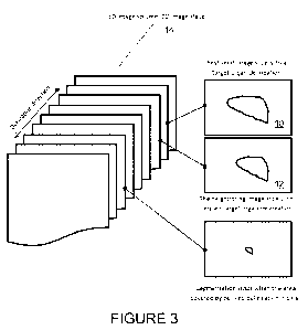
Figure 3 shows a diagram of an exemplary embodiment of a system of the present
invention, as described above with respect to Figure 2. Organ or anatomical
structure
segmentation is achieved using a deformation field generated with deformable
image
procedures between nearby neighboring 2-D image slices 10, 12 in the 3-D image
volume
14. The process is carried out in conjunction with a computing device or
computer with
a microprocessor or processor coupled to a memory.
CA 02833728 2013-10-18
WO 2012/145367
PCT/US2012/034030
8
Figure 4 shows an exemplary user interface of the system of the present
invention
as shown on a computer display. The image shown is the initialization and
result of the
segmentation of the seed image slice 60. Figure 5 shows the automated
segmentation
process being performed on neighboring slices sequentially 61, and the 3-D
stacking 62
of the segmented slices as they are produced.
In order to provide a context for the various aspects of the invention, the
following discussion provides a brief, general description of a suitable
computing
environment in which the various aspects of the present invention may be
implemented.
A computing system environment is one example of a suitable computing
environment,
but is not intended to suggest any limitation as to the scope of use or
functionality of the
invention. A computing environment may contain any one or combination of
components
discussed below, and may contain additional components, or some of the
illustrated
components may be absent. Various embodiments of the invention are operational
with
numerous general purpose or special purpose computing systems, environments or
configurations. Examples of computing systems, environments, or configurations
that
may be suitable for use with various embodiments of the invention include, but
are not
limited to, personal computers, laptop computers, computer servers, computer
notebooks,
hand-held devices, microprocessor-based systems, multiprocessor systems, TV
set-top
boxes and devices, programmable consumer electronics, cell phones, personal
digital
assistants (PDAs), network PCs, minicomputers, mainframe computers, embedded
systems, distributed computing environments, and the like.
Embodiments of the invention may be implemented in the form of computer-
executable instructions, such as program code or program modules, being
executed by a
CA 02833728 2013-10-18
WO 2012/145367
PCT/US2012/034030
9
computer or computing device. Program code or modules may include programs,
objections, components, data elements and structures, routines, subroutines,
functions and
the like. These are used to perform or implement particular tasks or
functions.
Embodiments of the invention also may be implemented in distributed computing
environments. In such environments, tasks are performed by remote processing
devices
linked via a communications network or other data transmission medium, and
data and
program code or modules may be located in both local and remote computer
storage
media including memory storage devices.
In one embodiment, a computer system comprises multiple client devices in
communication with at least one server device through or over a network. In
various
embodiments, the network may comprise the Internet, an intranet, Wide Area
Network
(WAN), or Local Area Network (LAN). It should be noted that many of the
methods of
the present invention are operable within a single computing device.
A client device may be any type of processor-based platform that is connected
to
a network and that interacts with one or more application programs. The client
devices
each comprise a computer-readable medium in the form of volatile and/or
nonvolatile
memory such as read only memory (ROM) and random access memory (RAM) in
communication with a processor. The processor executes computer-executable
program
instructions stored in memory. Examples of such processors include, but are
not limited
to, microprocessors, ASICs, and the like.
Client devices may further comprise computer-readable media in communication
with the processor, said media storing program code, modules and instructions
that, when
executed by the processor, cause the processor to execute the program and
perform the
CA 02833728 2013-10-18
WO 2012/145367
PCT/US2012/034030
steps described herein. Computer readable media can be any available media
that can be
accessed by computer or computing device and includes both volatile and
nonvolatile
media, and removable and non-removable media. Computer-readable media may
further
comprise computer storage media and communication media. Computer storage
media
5
comprises media for storage of information, such as computer readable
instructions, data,
data structures, or program code or modules. Examples of computer-readable
media
include, but are not limited to, any electronic, optical, magnetic, or other
storage or
transmission device, a floppy disk, hard disk drive, CD-ROM, DVD, magnetic
disk,
memory chip, ROM, RAM, EEPROM, flash memory or other memory technology, an
10 ASIC,
a configured processor, CDROM, DVD or other optical disk storage, magnetic
cassettes, magnetic tape, magnetic disk storage or other magnetic storage
devices, or any
other medium from which a computer processor can read instructions or that can
store
desired information. Communication media comprises media that may transmit or
carry
instructions to a computer, including, but not limited to, a router, private
or public
network, wired network, direct wired connection, wireless network, other
wireless media
(such as acoustic, RF, infrared, or the like) or other transmission device or
channel. This
may include computer readable instructions, data structures, program modules
or other
data in a modulated data signal such as a carrier wave or other transport
mechanism.
Said transmission may be wired, wireless, or both. Combinations of any of the
above
should also be included within the scope of computer readable media. The
instructions
may comprise code from any computer-programming language, including, for
example,
C, C++, C#, Visual Basic, Java, and the like.
CA 02833728 2013-10-18
WO 2012/145367
PCT/US2012/034030
11
Components of a general purpose client or computing device may further include
a system bus that connects various system components, including the memory and
processor. A system bus may be any of several types of bus structures,
including, but
not limited to, a memory bus or memory controller, a peripheral bus, and a
local bus
using any of a variety of bus architectures. Such architectures include, but
are not limited
to, Industry Standard Architecture (ISA) bus, Micro Channel Architecture (MCA)
bus,
Enhanced ISA (EISA) bus, Video Electronics Standards Association (VESA) local
bus,
and Peripheral Component Interconnect (PCI) bus.
Computing and client devices also may include a basic input/output system
(BIOS), which contains the basic routines that help to transfer information
between
elements within a computer, such as during start-up. BIOS typically is stored
in ROM.
In contrast, RAM typically contains data or program code or modules that are
accessible
to or presently being operated on by processor, such as, but not limited to,
the operating
system, application program, and data.
Client devices also may comprise a variety of other internal or external
components, such as a monitor or display, a keyboard, a mouse, a trackball, a
pointing
device, touch pad, microphone, joystick, satellite dish, scanner, a disk
drive, a CD-ROM
or DVD drive, or other input or output devices. These and other devices are
typically
connected to the processor through a user input interface coupled to the
system bus, but
may be connected by other interface and bus structures, such as a parallel
port, serial port,
game port or a universal serial bus (USB). A monitor or other type of display
device is
typically connected to the system bus via a video interface. In addition to
the monitor,
CA 02833728 2013-10-18
WO 2012/145367
PCT/US2012/034030
12
client devices may also include other peripheral output devices such as
speakers and
printer, which may be connected through an output peripheral interface.
Client devices may operate on any operating system capable of supporting an
application of the type disclosed herein. Client devices also may support a
browser or
browser-enabled application. Examples of client devices include, but are not
limited to,
personal computers, laptop computers, personal digital assistants, computer
notebooks,
hand-held devices, cellular phones, mobile phones, smart phones, pagers,
digital tablets,
Internet appliances, and other processor-based devices. Users may communicate
with
each other, and with other systems, networks, and devices, over the network
through the
respective client devices.
Thus, it should be understood that the embodiments and examples described
herein have been chosen and described in order to best illustrate the
principles of the
invention and its practical applications to thereby enable one of ordinary
skill in the art to
best utilize the invention in various embodiments and with various
modifications as are
suited for particular uses contemplated. Even though specific embodiments of
this
invention have been described, they are not to be taken as exhaustive. There
are several
variations that will be apparent to those skilled in the art.