Note: Descriptions are shown in the official language in which they were submitted.
CA 02833953 2013-11-21
260079
SYSTEM AND METHOD FOR DETECTING A GRID EVENT
FIELD OF THE INVENTION
The present subject matter relates generally to electrical machines and, more
particularly,
to a system and method for detecting a grid event on an electrical system
connected with
the one or more electrical machines.
BACKGROUND OF THE INVENTION
Generally, a wind turbine generator includes a turbine that has a rotor that
includes a
rotatable hub assembly having multiple blades. The blades transform mechanical
wind
energy into a mechanical rotational torque that drives one or more generators
via the
rotor. The generators are generally, but not always, rotationally coupled to
the rotor
through a gearbox. The gearbox steps up the inherently low rotational speed of
the rotor
for the generator to efficiently convert the rotational mechanical energy to
electrical
energy, which is fed into a utility grid via at least one electrical
connection. Gearless
direct drive wind turbine generators also exist. The rotor, generator, gearbox
and other
components are typically mounted within a housing, or nacelle, that is
positioned on top
of a base that may be a truss or tubular tower.
Some wind turbine generator configurations include doubly fed induction
generators
(DFIGs). Such configurations may also include power converters that are used
to
transmit generator excitation power to a wound generator rotor from one of the
connections to the electric utility grid connection. Moreover, such
converters, in
conjunction with the DFIG, also transmit electric power between the utility
grid and the
generator as well as transmit generator excitation power to a wound generator
rotor from
one of the connections to the electric utility grid connection. Alternatively,
some wind
turbine configurations include, but are not limited to, alternative types of
induction
generators, permanent magnet (PM) synchronous generators and electrically-
excited
synchronous generators and switched reluctance generators.
-1-
CA 02833953 2013-11-21
260079
These alternative configurations may also include power converters that are
used to
convert the frequencies as described above and transmit electrical power
between the
utility grid and the generator.
Similar to wind generation, solar power generation is becoming a progressively
larger
source of energy throughout the world. Solar power generation systems
typically include
one or more photovoltaic arrays (PV arrays) having multiple interconnected
solar cells
that convert solar energy into DC power through the photovoltaic effect. In
order to
interface the output of the PV arrays to a utility grid, a solar converter is
needed to
change the DC current and DC voltage output of the PV array into a 60/50 Hz AC
current
waveform that feeds power to the utility grid.
Various solar power converters exist for interfacing the DC output of a PV
array into AC
power. One implementation of a solar power converter consists of two stages, a
boost
converter stage and an inverter stage. The boost converter controls the flow
of DC power
from the PV array onto a DC bus. The inverter converts the power supplied to
the DC
bus into an AC current and AC voltage that can be output to the AC grid.
In some instances, electrical machines like sources of electrical generation
such as the
wind turbine generators or photovoltaic arrays described above may be located
in remote
areas far from the loads they serve. Typically, these sources of generation
are connected
to the electrical grid through an electrical system such as long transmission
lines. These
transmission lines are connected to the grid using one or more breakers. In
some
instances, a grid event can occur on these electrical systems. Such grid
events may cause
high voltage events, low voltage events, zero voltage events, frequency
shifts, phase
shifts and the like, that may detrimentally affect the one or more electrical
machines if
protective actions are not taken. In some instances, these grid events can be
caused by
opening of one or more phase conductors of the electrical system resulting in
islanding of
at least one of the one or more electrical machines. Islanding of these
electrical machines
by sudden tripping of the transmission line breaker at the grid side or
otherwise opening
these transmission lines while the source of generation is under heavy load
may result in
-2-
260079
an overvoltage on the transmission line that can lead to damage to the source
of generation
or equipment associated with the source of generation such as converters and
inverters.
Islanding generally requires disconnecting at least a portion of the affected
one or more
electrical machines from the electrical system to prevent damaging the
electrical machine
or equipment associated with the electrical machine. However, in other
instances, the grid
fault may not be islanding and may be a short term aberration to the
electrical system. In
these instances, it is desirous to keep the affected electrical machines
connected to the
electrical system and to institute ride-through procedures such as, for
example, high voltage
ride through (HVRT), low voltage ride through (LVRT) and zero voltage ride
through
(ZVRT). Exemplary systems and methods for HVRT, ZVRT and LVRT are described in
U.S. Patent Publication U.S. 20120133343 Al (application serial no. 13/323309)
filed
December 12, 2011; U.S. Patent No. 7,321,221 issued January 22, 2008; and U.S.
Patent
No. 6,921,985 issued July 26, 2005, respectively.
Failure to properly detect and manage the occurrence of islanding events in
wind turbines,
photovoltaic arrays, or other power generator systems can be very damaging to
those
systems, especially when the power generation system is using a doubly fed
induction
generator typology. When an upstream breaker opens and leaves the wind farm,
photovoltaic array or other power generation system isolated from the grid,
the ac voltage
seen by the power generation source can reach dangerous levels within a few
milliseconds. This high ac voltage is more extreme on systems where the
remaining
connection to the grid has substantial length of power lines that are seen as
a shunt
capacitance. The event also has potential for a higher degree of damage as the
power
output of the power generation source increases, for instance, if they are in
an overload
condition during high winds. In many instances, detection of a grid event,
such as
islanding, depend on injecting a signal into the grid that would tend to cause
a
disturbance in some parameter of the grid (such as a current, voltage,
frequency, or
phase), and measuring the amount this disturbance has on some parameter (such
as
a current, voltage, frequency, or phase). It is desirable to find a new method
of islanding
- 3 -
CA 2833953 2017-06-21
CA 02833953 2013-11-21
260079
detection without injecting a special voltage, current, phase, or frequency
disturbance into
the grid.
Accordingly, an improved system and/or method that provides for detecting a
grid event
without injecting a signal into the grid would be welcomed in the technology.
BRIEF DESCRIPTION OF THE INVENTION
In one aspect, a method for detecting a grid event is provided. The method
includes
sampling grid voltage and grid current over a fixed period of time;
determining grid
impedance at one or more frequencies using the sampled grid voltage and the
sampled
grid current; comparing the grid impedance at the one or more frequencies to a
known
expected grid impedance at the one or more frequencies; and detecting a grid
event based
on the comparison.
In another aspect, another method for detecting a grid event on an electrical
grid
connected with one or more electrical machines is provided. The method
includes
connecting one or more electrical machines to an alternating current (AC)
electric grid,
wherein the AC electric grid is configured to transmit at least one phase of
electrical
power to the one or more electrical machines or to receive at least one phase
of electrical
power from the one or more electrical machines; electrically coupling at least
a portion of
a control system to at least a portion of the AC electric grid; coupling at
least a portion of
the control system in electronic data communication with at least a portion of
the one or
more electrical machines; detecting a grid event of the AC electric grid based
on one or
more conditions monitored by the control system wherein the control system is
configured to: sample AC grid voltage and AC grid current over a fixed period
of time;
calculate a frequency transform of the sampled AC grid voltage and sampled AC
grid
current at one or more frequencies; determine grid impedance at the one or
more
frequencies using the calculated frequency transform of sampled AC grid
voltage divided
by the calculated transform of sampled AC grid current; compare the grid
impedance at
the one or more frequencies to a known expected grid impedance at the one or
more
frequencies and detect a grid event based on the comparison.
-4-
CA 02833953 2013-11-21
260079
In yet another aspect, a control system for detecting a grid event on an
alternating current
(AC) electrical grid connected with one or more electrical machines, the AC
electric grid
configured to transmit at least one phase of electrical power to the one or
more electrical
machines or to receive at least one phase of electrical power from the one or
more
electrical machines, is provided. The system includes a controller, wherein
the control
system is electrically coupled to at least a portion of the AC electric grid
and at least a
portion of the control system is coupled in electronic data communication with
at least a
portion of the one or more electrical machines, and wherein the controller is
configured
to: sample AC grid voltage and AC grid current over a fixed period of time;
determine
grid impedance at one or more frequencies using the sampled AC grid voltage
and the
sampled AC grid current; and detect whether a grid event is occurring or has
occurred by
compare the grid impedance at the one or more frequencies to a known expected
grid
impedance at the one or more frequencies; and detect a grid event based on the
comparison.
These and other features, aspects and advantages of the present invention will
become
better understood with reference to the following description and appended
claims. The
accompanying drawings, which are incorporated in and constitute a part of this
specification, illustrate embodiments of the invention and, together with the
description,
serve to explain the principles of the invention.
BRIEF DESCRIPTION OF THE DRAWINGS
A full and enabling disclosure of embodiments of the present invention,
including the
best mode thereof, directed to one of ordinary skill in the art, is set forth
in the
specification, which makes reference to the appended figures, in which:
FIG. 1 is a schematic view of an exemplary wind turbine generator;
FIG. 2 is a schematic view of an exemplary electrical and control system that
may
be used with the wind turbine generator shown in FIG. 1;
FIGS. 3A and 38 show examples of grid impedance with a normal grid (FIG. 3A)
and when an islanding condition exists (FIG. 3B);
-5-
CA 02833953 2013-11-21
260079
FIG. 3C illustrates a portion of the graph of normal grid impedance (FIG. 3A)
overlaid with a portion of the graph of impedance during an open grid (e.g.,
an islanding
condition) (FIG. 3B) to show the difference in impedance magnitude at the
various
frequencies;
FIG. 4 illustrates a block diagram of one embodiment of suitable components
that
may be included within an embodiment of a controller, or any other computing
device
that receives signals indicating a grid fault in accordance with aspects of
the present
subject matter; and
FIG. 5 is a flowchart illustrating an embodiment of a method of detecting a
grid
event on an electrical system connected with one or more electrical machines
such as
wind turbine generators.
DETAILED DESCRIPTION OF THE INVENTION
Before the present methods and systems are disclosed and described, it is to
be
understood that the methods and systems are not limited to specific synthetic
methods,
specific components, or to particular compositions. It is also to be
understood that the
terminology used herein is for describing particular embodiments only and is
not
intended to be limiting.
As used in the specification and the appended claims, the singular forms "a,"
"an" and
"the" include plural referents unless the context clearly dictates otherwise.
Ranges may
be expressed herein as from "about" one particular value, and/or to "about"
another
particular value. When such a range is expressed, another embodiment includes
from the
one particular value and/or to the other particular value. Similarly, when
values are
expressed as approximations, by use of the antecedent "about," it will be
understood that
the particular value forms another embodiment. It will be further understood
that the
endpoints of each of the ranges are significant both in relation to the other
endpoint, and
independently of the other endpoint.
-6-
CA 02833953 2013-11-21
260079
"Optional" or "optionally" means that the subsequently described event or
circumstance
may or may not occur, and that the description includes instances where said
event or
circumstance occurs and instances where it does not.
Throughout the description and claims of this specification, the word
"comprise" and
variations of the word, such as "comprising" and "comprises," means "including
but not
limited to," and is not intended to exclude, for example, other additives,
components,
integers or steps. "Exemplary" means "an example of' and is not intended to
convey an
indication of a preferred or ideal embodiment. "Such as" is not used in a
restrictive
sense, but for explanatory purposes.
Disclosed are components that can be used to perform the disclosed methods and
systems. These and other components are disclosed herein, and it is understood
that when
combinations, subsets, interactions, groups, etc. of these components are
disclosed that
while specific reference of each various individual and collective
combinations and
permutation of these may not be explicitly disclosed, each is specifically
contemplated
and described herein, for all methods and systems. This applies to all aspects
of this
application including, but not limited to, steps in disclosed methods. Thus,
if there are a
variety of additional steps that can be performed it is understood that each
of these
additional steps can be performed with any specific embodiment or combination
of
embodiments of the disclosed methods.
The present methods and systems may be understood more readily by reference to
the
following detailed description of preferred embodiments and the Examples
included
therein and to the Figures and their previous and following description.
Generally disclosed herein are systems and methods of detecting a grid event
on an
electrical grid connected with one or more electrical machines. Such
electrical machines
can include, for example, electric motors; electric generators including, for
example,
wind turbine generators, gas turbine generators, steam turbine generators, and
the like;
solar/photovoltaic generation; and the like, and any ancillary equipment
associated with
such electric machines. In one aspect, embodiments of the present invention
disclose
-7-
CA 02833953 2013-11-21
260079
systems and methods to rapidly detect a grid event on an electrical system
connected to
one or more electrical machines such as wind turbine generators or
photovoltaic arrays by
sampling grid voltage and grid current over a fixed period of time;
determining grid
impedance at one or more frequencies using the sampled grid voltage and the
sampled
grid current; and detecting whether a grid event is occurring or has occurred
by
comparing the grid impedance at the one or more frequencies to a known
expected grid
impedance range at the one or more frequencies.
Consider as a non-limiting example FIG. 1, which is a schematic view of an
exemplary
wind turbine generator 100. The wind turbine 100 includes a nacelle 102
housing a
generator (not shown in FIG. 1). Nacelle 102 is mounted on a tower 104 (a
portion of
tower 104 being shown in FIG. 1). Tower 104 may be any height that facilitates
operation of wind turbine 100 as described herein. Wind turbine 100 also
includes a rotor
106 that includes three rotor blades 108 attached to a rotating hub 110.
Alternatively,
wind turbine 100 includes any number of blades 108 that facilitate operation
of wind
turbine 100 as described herein. In the exemplary embodiment, wind turbine 100
includes a gearbox (not shown in FIG. 1) rotatingly coupled to rotor 106 and a
generator
(not shown in FIG. 1).
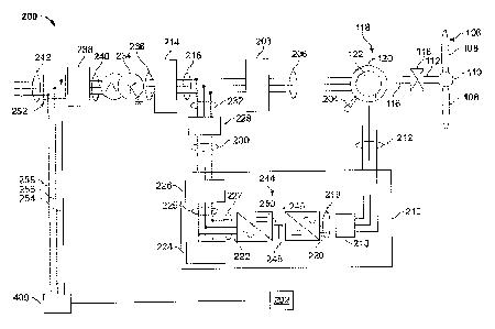
FIG. 2 is a schematic view of an exemplary electrical and control system 200
that may be
used with wind turbine generator 100 (shown in FIG. 1). Rotor 106 includes
plurality of
rotor blades 108 coupled to rotating hub 110. Rotor 106 also includes a low-
speed shaft
112 rotatably coupled to hub 110. Low-speed shaft is coupled to a step-up
gearbox 114.
Gearbox 114 is configured to step up the rotational speed of low-speed shaft
112 and
transfer that speed to a high-speed shaft 116. In the exemplary embodiment,
gearbox 114
has a step-up ratio of approximately 70:1. For example, low-speed shaft 112
rotating at
approximately 20 revolutions per minute (20) coupled to gearbox 114 with an
approximately 70:1 step-up ratio generates a high-speed shaft 116 speed of
approximately
1400 rpm. Alternatively, gearbox 114 has any step-up ratio that facilitates
operation of
wind turbine 100 as described herein. Also, alternatively, wind turbine 100
includes a
-8-
CA 02833953 2013-11-21
260079
direct-drive generator wherein a generator rotor (not shown in FIG. 1) is
rotatingly
coupled to rotor 106 without any intervening gearbox.
High-speed shaft 116 is rotatably coupled to generator 118. In the exemplary
embodiment, generator 118 is a wound rotor, synchronous, 60 Hz, three-phase,
doubly-
fed induction generator (DFIG) that includes a generator stator 120
magnetically coupled
to a generator rotor 122. Alternatively, generator 118 is any generator of any
number of
phases that facilitates operation of wind turbine 100 as described herein.
Electrical and control system 200 includes a controller 202. Controller 202
includes at
least one processor and a memory, at least one processor input channel, at
least one
processor output channel, and may include at least one computer (none shown in
FIG. 2).
As used herein, the term computer is not limited to just those integrated
circuits referred
to in the art as a computer, but broadly refers to a processor, a
microcontroller, a
microcomputer, a programmable logic controller (PLC), an application specific
integrated
circuit, and other programmable circuits (none shown in FIG. 2), and these
terms are used
interchangeably herein. In the exemplary embodiment, memory may include, but
is not
limited to, a computer-readable medium, such as a random access memory (RAM)
(none
shown in FIG. 2). Alternatively, a floppy disk, a compact disc ¨ read only
memory (CD-
ROM), a magneto-optical disk (MOD), and/or a digital versatile disc (DVD)
(none shown
in FIG. 2) may also be used. Also, in the exemplary embodiment, additional
input
channels (not shown in FIG. 2) may be, but not be limited to, computer
peripherals
associated with an operator interface such as a mouse and a keyboard (neither
shown in
FIG. 2). Alternatively, other computer peripherals may also be used that may
include, for
example, but not be limited to, a scanner (not shown in FIG. 2). Furthermore,
in the
exemplary embodiment, additional output channels may include, but not be
limited to, an
operator interface monitor (not shown in FIG. 2).
Processors for controller 202 process information transmitted from a plurality
of
electrical and electronic devices that may include, but not be limited to,
speed and power
transducers, current transformers and/or current transducers, breaker position
indicators,
-9-
CA 02833953 2013-11-21
260079
potential transformers and/or voltage transducers, and the like. RAM and
storage device
store and transfer information and instructions to be executed by the
processor. RAM
and storage devices can also be used to store and provide temporary variables,
static (i.e.,
non-changing) information and instructions, or other intermediate information
to the
processors during execution of instructions by the processors. Instructions
that are
executed include, but are not limited to, resident conversion and/or
comparator
algorithms. The execution of sequences of instructions is not limited to any
specific
combination of hardware circuitry and software instructions.
Electrical and control system 200 also includes generator rotor tachometer 204
that is
coupled in electronic data communication with generator 118 and controller
202.
Generator stator 120 is electrically coupled to a stator synchronizing switch
206 via a
stator bus 208. In the exemplary embodiment, to facilitate the DFIG
configuration,
generator rotor 122 is electrically coupled to a hi-directional power
conversion assembly
210 via a rotor bus 212. Alternatively, system 200 is configured as a full
power
conversion system (not shown) known in the art, wherein a full power
conversion
assembly (not shown) that is similar in design and operation to assembly 210
is
electrically coupled to stator 120 and such full power conversion assembly
facilitates
channeling electrical power between stator 120 and an electric power
transmission and
distribution grid (not shown). Stator bus 208 transmits three-phase power from
stator 120
and rotor bus 212 transmits three-phase power from rotor 122 to assembly 210.
Stator
synchronizing switch 206 is electrically coupled to a main transformer circuit
breaker 214
via a system bus 216.
Assembly 210 includes a rotor filter 218 that is electrically coupled to rotor
122 via rotor
bus 212. Rotor filter 218 is electrically coupled to a rotor-side, bi-
directional power
converter 220 via a rotor filter bus 219. Converter 220 is electrically
coupled to a line-
side, bi-directional power converter 222. Converters 220 and 222 are
substantially
identical. Power converter 222 is electrically coupled to a line filter 224
and a line
contactor 226 via a line-side power converter bus 223 and a line bus 225. In
the
exemplary embodiment, converters 220 and 222 are configured in a three-phase,
pulse
-10-
CA 02833953 2013-11-21
260079
width modulation (PWM) configuration including insulated gate bipolar
transistor
(IGBT) switching devices (not shown in FIG. 2) that "fire" as is known in the
art.
Alternatively, converters 220 and 222 have any configuration using any
switching
devices that facilitate operation of system 200 as described herein. Assembly
210 is
coupled in electronic data communication with controller 202 to control the
operation of
converters 220 and 222.
Line contactor 226 is electrically coupled to a conversion circuit breaker 228
via a
conversion circuit breaker bus 230. Circuit breaker 228 is also electrically
coupled to
system circuit breaker 214 via system bus 216 and connection bus 232. System
circuit
breaker 214 is electrically coupled to an electric power main transformer 234
via a
generator-side bus 236. Main transformer 234 is electrically coupled to a grid
circuit
breaker 238 via a breaker-side bus 240. Grid breaker 238 is connected to an
electric
power transmission and distribution grid via a grid bus 242.
In the exemplary embodiment, converters 220 and 222 are coupled in electrical
communication with each other via a single direct current (DC) link 244.
Alternatively,
converters 220 and 222 are electrically coupled via individual and separate DC
links (not
shown in FIG. 2). DC link 244 includes a positive rail 246, a negative rail
248, and at
least one capacitor 250 coupled therebetween. Alternatively, capacitor 250 is
one or
more capacitors configured in series or in parallel between rails 246 and 248.
System 200 can further include a phase-locked loop (PLL) regulator 400 that is
configured to receive a plurality of voltage measurement signals from a
plurality of
voltage transducers 252. In the exemplary embodiment, each of three voltage
transducers
252 are electrically coupled to each one of the three phases of bus 242.
Alternatively,
voltage transducers 252 are electrically coupled to system bus 216. Also,
alternatively,
voltage transducers 252 are electrically coupled to any portion of system 200
that
facilitates operation of system 200 as described herein. PLL regulator 400 is
coupled in
electronic data communication with controller 202 and voltage transducers 252
via a
plurality of electrical conduits 254, 256, and 258. Alternatively, PLL
regulator 400 is
-11-
CA 02833953 2013-11-21
260079
configured to receive any number of voltage measurement signals from any
number of
voltage transducers 252, including, but not limited to, one voltage
measurement signal
from one voltage transducer 252. Controller 202 can also receive any number of
current
feedbacks from current transformers or current transducers that are
electrically coupled to
any portion of system 200 that facilitates operation of system 200 as
described herein
such as, for example, stator current feedback from stator bus 208, grid
current feedback
from generator side bus 236, and the like.
During operation, wind impacts blades 108 and blades 108 transform mechanical
wind
energy into a mechanical rotational torque that rotatingly drives low-speed
shaft 112 via
hub 110. Low-speed shaft 112 drives gearbox 114 that subsequently steps up the
low
rotational speed of shaft 112 to drive high-speed shaft 116 at an increased
rotational
speed. High speed shaft 116 rotatingly drives rotor 122. A rotating magnetic
field is
induced within rotor 122 and a voltage is induced within stator 120 that is
magnetically
coupled to rotor 122. Generator 118 converts the rotational mechanical energy
to a
sinusoidal, three-phase alternating current (AC) electrical energy signal in
stator 120.
The associated electrical power is transmitted to main transformer 234 via bus
208,
switch 206, bus 216, breaker 214 and bus 236. Main transformer 234 steps up
the voltage
amplitude of the electrical power and the transformed electrical power is
further
transmitted to an electrical grid (not shown FIG. 2) via bus 240, circuit
breaker 238 and
bus 242.
In the doubly-fed induction generator configuration, a second electrical power
transmission path is provided. Electrical, three-phase, sinusoidal, AC power
is generated
within wound rotor 122 and is transmitted to assembly 210 via bus 212. Within
assembly
210, the electrical power is transmitted to rotor filter 218 wherein the
electrical power is
modified for the rate of change of the PWM signals associated with converter
220.
Converter 220 acts as a rectifier and rectifies the sinusoidal, three-phase AC
power to DC
power. The DC power is transmitted into DC link 244. Capacitor 250 facilitates
mitigating DC link 244 voltage amplitude variations by facilitating mitigation
of a DC
ripple associated with AC rectification.
-12-
CA 02833953 2013-11-21
260079
The DC power is subsequently transmitted from DC link 244 to power converter
222
wherein converter 222 acts as an inverter configured to convert the DC
electrical power
from DC link 244 to three-phase, sinusoidal AC electrical power with pre-
determined
voltages, currents, and frequencies. This conversion is monitored and
controlled via
controller 202. The converted AC power is transmitted from converter 222 to
bus 216
via buses 227 and 225, line contactor 226, bus 230, circuit breaker 228, and
bus 232.
Line filter 224 compensates or adjusts for harmonic currents in the electric
power
transmitted from converter 222. Stator synchronizing switch 206 is configured
to close
such that connecting the three-phase power from stator 120 with the three-
phase power
from assembly 210 is facilitated.
Circuit breakers 228, 214, and 238 are configured to disconnect corresponding
buses, for
example, when current flow is excessive and can damage the components of the
system
200. Additional protection components are also provided, including line
contactor 226,
which may be controlled to form a disconnect by opening a switch (not shown in
FIG. 2)
corresponding to each of the lines of the line bus 230.
Assembly 210 compensates or adjusts the frequency of the three-phase power
from rotor
122 for changes, for example, in the wind speed at hub 110 and blades 108.
Therefore, in
this manner, mechanical and electrical rotor frequencies are decoupled and the
electrical
stator and rotor frequency matching is facilitated substantially independently
of the
mechanical rotor speed.
Under some conditions, the bi-directional characteristics of assembly 210, and
specifically, the bi-directional characteristics of converters 220 and 222,
facilitate feeding
back at least some of the generated electrical power into generator rotor 122.
More
specifically, electrical power is transmitted from bus 216 to bus 232 and
subsequently
through circuit breaker 228 and bus 230 into assembly 210. Within assembly
210, the
electrical power is transmitted through line contactor 226 and busses 225 and
227 into
power converter 222. Converter 222 acts as a rectifier and rectifies the
sinusoidal, three-
phase AC power to DC power. The DC power is transmitted into DC link 244.
-13-
CA 02833953 2013-11-21
260079
Capacitor 250 facilitates mitigating DC link 244 voltage amplitude variations
by
facilitating mitigation of a DC ripple sometimes associated with three-phase
AC
rectification.
The DC power is subsequently transmitted from DC link 244 to power converter
220
wherein converter 220 acts as an inverter configured to convert the DC
electrical power
transmitted from DC link 244 to a three-phase, sinusoidal AC electrical power
with pre-
determined voltages, currents, and frequencies. This conversion is monitored
and
controlled via controller 202. The converted AC power is transmitted from
converter 220
to rotor filter 218 via bus 219 is subsequently transmitted to rotor 122 via
bus 212. In this
manner, generator reactive power control is facilitated.
Assembly 210 is configured to receive control signals from controller 202. The
control
signals are based on sensed conditions or operating characteristics of wind
turbine 100
and system 200 as described herein and used to control the operation of the
power
conversion assembly 210. For example, tachometer 204 feedback in the form of
sensed
speed of the generator rotor 122 may be used to control the conversion of the
output
power from rotor bus 212 to maintain a proper and balanced three-phase power
condition.
Other feedback from other sensors also may be used by system 200 to control
assembly
210 including, for example, stator and rotor bus voltages and current
feedbacks, grid
current, grid voltage, grid frequency, and the like. Using this feedback
information, and
for example, switching control signals, stator synchronizing switch control
signals,
system circuit breaker control (trip) signals, and other signals for
controlling the
generator 118, converter system 210, grid, and the like may be generated in
any known
manner. For example, for a grid event with predetermined characteristics such
as
islanding, controller 202 may take actions including, for example, temporarily
substantially suspend firing of the IGBTs within converters 220, 222. This
process can
also be referred to as "gating off' the IGBTs in converters 220, 222. Such
suspension of
operation of converters 220, 222 will substantially mitigate electric power
being
channeled through conversion assembly 210 to approximately zero.
-14-
CA 02833953 2013-11-21
260079
As shown in FIG. 2, a power source such as generator 118 can be coupled to a
utility grid
through a power converter system 210. Under normal operating conditions, the
power
converter system 210 can generate a frequency spectrum of output currents
based on the
PWM method of creating the fundamental frequency by modulating a higher
frequency
carrier waveform. This spectrum of output currents can have strong components
at the
fundamental frequency as well as at the carrier frequency and various
combinations/multiples of the two. Effectively the power converter 210
naturally creates
a broadband noise source as part of its normal operation. It is not necessary
to inject any
special signal into the grid to determine a grid event such as an islanding
condition.
Instead, it is possible to measure the grid impedance, using the natural
broadband noise
source of the converter, by determining grid impedance at one or more
frequencies and
comparing the measured grid impedance at the one or more frequencies at any
time to the
expected grid impedance or ranges of grid impedance of a normal grid at the
one or more
frequencies. In one aspect, grid impedance at the one or more frequencies can
be
determined by taking frequency-domain transforms (e.g., Fast Fourier
transforms (FFT),
Discrete Fourier transforms (DFT), and the like) of grid voltage and grid
current. In
another aspect, grid impedance at the one or more frequencies can be
determined by
filtering of grid voltage and grid current at one or more frequencies.
Embodiments of the
invention are intended to encompass any method of determining grid impedance
at the
one or more frequencies from sampled grid voltage and grid current. Regardless
of the
method used to determine grid impedance at one or more frequencies, once
determined
the measured grid impedance at one or more frequencies at any time can be
compared to
the expected grid impedance of a normal grid at one or more frequencies to
determine if a
grid event, such as islanding, is occurring or has occurred. FIGS. 3A and 3B
show
examples of grid impedance with a normal grid (FIG. 3A) and when an islanding
condition exists (FIG. 3B), particularly evident at the frequencies with high
energy
produced by the converter system 210. FIG. 3A shows exemplary graphs of normal
grid
conditions. The top graph of FIG. 3A shows the a magnitude of FFT of grid
voltage
divided by a FFT of grid current at various frequencies, the second from the
top graph of
FIG. 3A shows a phase FFT of grid voltage divided by a FFT of grid current at
various
-15-
CA 02833953 2013-11-21
260079
frequencies; the third from the top graph of FIG. 3A shows a magnitude FFT of
grid
current at various frequencies and the bottom graph of FIG. 3A shows a
magnitude FFT
of grid voltage at various frequencies. FIG. 3B shows exemplary graphs of grid
conditions during a grid event such as islanding. The top graph of FIG. 3B
shows the a
magnitude of FFT of grid voltage divided by a FFT of grid current at various
frequencies,
the second from the top graph of FIG. 3B shows a phase FFT of grid voltage
divided by a
FFT of grid current at various frequencies; the third from the top graph of
FIG. 3B shows
a magnitude FFT of grid current at various frequencies and the bottom graph of
FIG. 3B
shows a magnitude FFT of grid voltage at various frequencies. As can be seen,
there is a
significant change in the grid impedance at one or more frequencies when a
grid event
such as an islanding condition exists. Therefore, it can be seen that the
change in
impedance at the various frequencies can be used to detect a grid event such
as islanding.
FIG. 3C illustrates a portion of the graph of normal grid impedance (FIG. 3A)
overlaid
with a portion of the graph of impedance during an open grid (e.g., an
islanding
condition) (FIG. 3B) to show the difference in impedance magnitude at the
various
frequencies. As can be seen, the line 302 denoting normal grid impedance
varies
significantly from the line 304 denoting grid impedance during an open grid
condition
such as islanding at various frequencies. This difference can be used to
detect grid events
that are occurring or have occurred on the electrical system.
Referring now to FIG. 4, as noted above, some embodiments of systems for
detecting
grid events can include a control system or controller 202. In general, the
controller 202
may comprise a computer or other suitable processing unit. Thus, in several
embodiments, the controller 202 may include suitable computer-readable
instructions
that, when implemented, configure the controller 202 to perform various
different
functions, such as receiving, transmitting and/or executing control signals.
As such, the
controller 202 may generally be configured to control the various operating
modes (e.g.,
conducting or non-conducting states) of the one or more switches and/or
components of
embodiments of the electrical system 200. For example, the controller 200 may
be
-16-
CA 02833953 2013-11-21
260079
configured to implement methods of detecting a grid event on an electrical
system
connected with the one or more electrical machines.
FIG. 4 illustrates a block diagram of one embodiment of suitable components
that may be
included within an embodiment of a controller 202, or any other computing
device that
receives signals indicating grid conditions in accordance with aspects of the
present
subject matter. In various aspects, such signals can be received from one or
more sensors
or transducers 58, 60, or may be received from other computing devices (not
shown) such
as a supervisory control and data acquisition (SCADA) system, a turbine
protection
system, PLL regulator 400 and the like. Received signals can include, for
example,
voltage signals such as DC bus 244 voltage and AC grid voltage along with
corresponding phase angles for each phase of the AC grid, current signals,
power flow
(direction) signals, power output from the converter system 210, total power
flow into (or
out of) the grid, and the like. In some instances, signals received can be
used by the
controller 202 to calculate other variables such as changes in voltage phase
angles over
time, changes in impedance at various frequencies, and the like. As shown, the
controller
202 may include one or more processor(s) 62 and associated memory device(s) 64
configured to perform a variety of computer-implemented functions (e.g.,
performing the
methods, steps, calculations and the like disclosed herein). As used herein,
the term
"processor" refers not only to integrated circuits referred to in the art as
being included in
a computer, but also refers to a controller, a microcontroller, a
microcomputer, a
programmable logic controller (PLC), an application specific integrated
circuit, and other
programmable circuits. Additionally, the memory device(s) 64 may generally
comprise
memory element(s) including, but not limited to, computer readable medium
(e.g.,
random access memory (RAM)), computer readable non-volatile medium (e.g., a
flash
memory), a floppy disk, a compact disc-read only memory (CD-ROM), a magneto-
optical disk (MOD), a digital versatile disc (DVD) and/or other suitable
memory
elements. Such memory device(s) 64 may generally be configured to store
suitable
computer-readable instructions that, when implemented by the processor(s) 62,
configure
the controller 202 to perform various functions including, but not limited to,
directly or
-17-
CA 02833953 2013-11-21
260079
indirectly transmitting suitable control signals to one or more switches that
comprise the
bi-directional power conversion assembly 210, monitoring operating conditions
of the
electrical system 200, and various other suitable computer-implemented
functions.
Additionally, the controller 202 may also include a communications module 66
to
facilitate communications between the controller 202 and the various
components of the
electrical system 200 and/or the one or more sources of electrical generation
118. For
instance, the communications module 66 may serve as an interface to permit the
controller 202 to transmit control signals to one or more switches that
comprise the bi-
directional power conversion assembly 210 to change to a conducting or non-
conducting
state or to control any other device or component that comprises the
electrical system
200. Moreover, the communications module 66 may include a sensor interface 68
(e.g.,
one or more analog-to-digital converters) to permit signals transmitted from
the sensors
(e.g., 58, 60) to be converted into signals that can be understood and
processed by the
processors 62. Alternatively, the controller 202 may be provided with suitable
computer
readable instructions that, when implemented by its processor(s) 62, configure
the
controller 202 to determine based on a first received indicator whether an
islanding of the
one or more sources of electrical generation 118 has occurred based on
information
stored within its memory 64 and/or based on an input received from the
electrical system
by the controller 202. Similarly, the controller 202 may be provided with
suitable
computer readable instructions that, when implemented by its processor(s) 62,
configure
the controller 202 to determine based on the one or more additional condition
indicators
whether a grid event on an electrical system connected with the one or more
electrical
machines 118 has occurred based on information stored within its memory 64
and/or
based on other inputs received from the electrical system 200 by the
controller 202.
FIG. 5 is a flowchart illustrating an embodiment of a method of detecting a
grid event on
an electrical system connected with one or more electrical machines such as
wind turbine
generators. Embodiments of steps of the method described in FIG. 5 can be
performed
by one or more computing devices such as controller 202. At step 502, grid
voltage and
grid current are sampled over a fixed period of time. The sampling period can
be any
-18-
CA 02833953 2013-11-21
260079
period of time as desired. For example, in one aspect sampling grid voltage
and grid
current over the fixed period of time comprises sampling grid voltage and grid
current
over one cycle of a fundamental frequency, as the fundamental frequency is
determined
by a frequency-domain transform of the grid voltage or grid current. In some
instances,
the fixed period of time may cause an undesirable delay in detecting a grid
event.
Therefore, the defined time period for sampling may be reduced so that when
using FFT
analysis or any other method to calculate impedance for detecting a grid
event, the
analysis may be updated every few microseconds.
At step 504, grid impedance can be determined using the sampled grid voltage
and the
sampled grid current. In one aspect, determining grid impedance at one or more
frequencies using the sampled grid voltage and the sampled grid current
comprises
calculating a transform of the sampled grid voltage and sampled grid current
at the one or
more frequencies and determining the grid impedance at the one or more
frequencies
using the calculated transform of sampled grid voltage divided by the
calculated
transform of sampled grid current. In one aspect, calculating the transform of
the
sampled grid voltage and sampled grid current comprises calculating a Fourier
transform
of the sampled grid voltage and sampled grid current. In one aspect,
calculating the
Fourier transform of the sampled grid voltage and sampled grid current
comprises
calculating a fast Fourier transform (FFT) of at least one of the sampled grid
voltage and
sampled grid current or a DFT of at least one of the sampled grid voltage and
sampled
grid current. In one aspect, a frequency response or transfer function of a
system can be
calculated using power spectra of an impulse/transient/noise input, x, and
correlated
output, y, by determing where there is the cross correlation (crosspower
spectrum)
between output and input and the autoconelation (autopower spectrum) of the
output.
The idea can be extended to determine grid impedance by analyzing the grid
transient
currents and voltages. The above ratio (V/I) can be calculated by using, for
example, the
Welch method: (1) Divide the input and output data in equal numbers of
overlapping
segments; (2) Apply a windowing function on each segment for both input and
output;
(3) Apply n-point FFT on each windowed segment for both input and output; (4)
-19-
CA 02833953 2013-11-21
260079
Compute modified periodogram for each windowed segment of the output; (5)
Compute
modified periodogram for respective windowed segments of input and output; (6)
Auto-
spectrum estimate is formed by averaging all the modified periodograms for the
output
stream; (7) Cross-spectrum estimate is formed by averaging all the modified
periodograms for input/output streams; (8) Appropriately scale the resultant
spectrum
estimates to compute power spectral densities; and (9) Take the ratio (V/I) as
shown
above to calculate impedance over a frequency range.
In another aspect, determining grid impedance at one or more frequencies using
the
sampled grid voltage and the sampled grid current comprises filtering the grid
voltage
and filtering the grid current at the one or more frequencies and determining
the grid
impedance at the one or more frequencies using the filtered grid voltage
divided by the
filtered grid current at the one or more frequencies.
At step 506, the grid impedance at the one or more frequencies can be compared
to a
known expected grid impedance or range of grid impedance at the one or more
frequencies. In one aspect, comparing the grid impedance at the one or more
frequencies
to the known expected grid impedance or range of grid impedance at the one or
more
frequencies comprises comparing the grid impedance at the one or more
frequencies to
the known expected grid impedance or range of grid impedance at one or more
selected
frequencies. At step 508, a grid event can be detected based on the comparison
performed in step 506. In various aspects, detecting a grid event can be
performed by
comparing calculated magnitude, phase, or some combination of the two with a
known
expected grid impedance or range of grid impedance (magnitude, phase, or some
combination of the two). Aspects of the calculated impedance at the one or
more
frequencies as compared to the known expected impedance or range of grid
impedance at
the one or more frequencies can be used to detect grid events. For example,
the effective
resistance of the impedance (damping for real resistance, or divergent for
negative
resistance), as well as the shift in the grid impedance from inductive to
capacitive during
an islanding event can be used for detection. In one aspect, detecting the
grid event by
comparing the grid impedance at the one or more frequencies to the known
expected grid
-20-
CA 02833953 2013-11-21
260079
impedance or range of grid impedance comprises detecting that the grid event
is
occurring or has occurred if the grid impedance at the one or more frequencies
is outside
the known expected grid impedance or range of grid impedance at the one or
more
frequencies. In another example, detecting the grid event by comparing the
grid
impedance at the one or more frequencies to the known expected grid impedance
or range
of grid impedance at the one or more frequencies comprises detecting that the
grid event
is not occurring or has not occurred if the grid impedance at the one or more
frequencies
is within the known expected grid impedance or range of grid impedance at the
one or
more frequencies. In one aspect, detecting the grid event based on the
comparison
comprises detecting that the grid event comprises islanding of an electrical
generator.
For example, the electrical generator can comprise a doubly-fed induction
generator
(DFIG) driven by a wind turbine or a photovoltaic array.
As described above and as will be appreciated by one skilled in the art,
embodiments of
the present invention may be configured as a system, method, or a computer
program
product. Accordingly, embodiments of the present invention may be comprised of
various means including entirely of hardware, entirely of software, or any
combination of
software and hardware. Furthermore, embodiments of the present invention may
take the
form of a computer program product on a computer-readable storage medium
having
computer-readable program instructions (e.g., computer software) embodied in
the
storage medium. Any suitable non-transitory computer-readable storage medium
may be
utilized including hard disks, CD-ROMs, optical storage devices, or magnetic
storage
devices.
Embodiments of the present invention have been described above with reference
to block
diagrams and flowchart illustrations of methods, apparatuses (i.e., systems)
and computer
program products. It will be understood that each block of the block diagrams
and
flowchart illustrations, and combinations of blocks in the block diagrams and
flowchart
illustrations, respectively, can be implemented by various means including
computer
program instructions. These computer program instructions may be loaded onto a
general
purpose computer, special purpose computer, or other programmable data
processing
-21-
CA 02833953 2013-11-21
260079
apparatus, such as the processor(s) 62 discussed above with reference to FIG.
4, to
produce a machine, such that the instructions which execute on the computer or
other
programmable data processing apparatus create a means for implementing the
functions
specified in the flowchart block or blocks.
These computer program instructions may also be stored in a non-transitory
computer-
readable memory that can direct a computer or other programmable data
processing
apparatus (e.g., processor(s) 62 of FIG. 4) to function in a particular
manner, such that the
instructions stored in the computer-readable memory produce an article of
manufacture
including computer-readable instructions for implementing the function
specified in the
flowchart block or blocks. The computer program instructions may also be
loaded onto a
computer or other programmable data processing apparatus to cause a series of
operational steps to be performed on the computer or other programmable
apparatus to
produce a computer-implemented process such that the instructions that execute
on the
computer or other programmable apparatus provide steps for implementing the
functions
specified in the flowchart block or blocks.
Accordingly, blocks of the block diagrams and flowchart illustrations support
combinations of means for performing the specified functions, combinations of
steps for
performing the specified functions and program instruction means for
performing the
specified functions. It will also be understood that each block of the block
diagrams and
flowchart illustrations, and combinations of blocks in the block diagrams and
flowchart
illustrations, can be implemented by special purpose hardware-based computer
systems
that perform the specified functions or steps, or combinations of special
purpose
hardware and computer instructions.
Unless otherwise expressly stated, it is in no way intended that any method
set forth
herein be construed as requiring that its steps be performed in a specific
order.
Accordingly, where a method claim does not actually recite an order to be
followed by its
steps or it is not otherwise specifically stated in the claims or descriptions
that the steps
are to be limited to a specific order, it is no way intended that an order be
inferred, in any
-22-
260079
respect. This holds for any possible non-express basis for interpretation,
including: matters
of logic with respect to arrangement of steps or operational flow; plain
meaning derived
from grammatical organization or punctuation; the number or type of
embodiments
described in the specification.
Many modifications and other embodiments of the inventions set forth herein
will come to
mind to one skilled in the art to which these embodiments of the invention
pertain having
the benefit of the teachings presented in the foregoing descriptions and the
associated
drawings. Therefore, it is to be understood that the embodiments of the
invention are not
to be limited to the specific embodiments disclosed and that modifications and
other
embodiments are intended to be included within the scope of the appended
claims.
Moreover, although the foregoing descriptions and the associated drawings
describe
exemplary embodiments in the context of certain exemplary combinations of
elements
and/or functions, it should be appreciated that different combinations of
elements and/or
functions may be provided by alternative embodiments without departing from
the scope
of the appended claims. In this regard, for example, different combinations of
elements
and/or functions than those explicitly described above are also contemplated
as may be set
forth in some of the appended claims. Although specific terms are employed
herein, they
are used in a generic and descriptive sense only and not for purposes of
limitation.
- 23 -
CA 2833953 2017-06-21