Note: Descriptions are shown in the official language in which they were submitted.
1
CA 02834995 2013-11-01
Description
VEHICLE-BODY INCLINATION DEVICE AND DOUBLE-LAYER THREE-WAY VALVE
USED IN VEHICLE-BODY INCLINATION DEVICE
Technical Field
[0001]
The present invention relates to a carriage-body inclination
device and to a two-layer three-way valve used in the carriage-body
inclination device, and in particular to a carriage-body
inclination device which inclines a carriage body with respect to
a dolly by expanding or contracting an air spring provided between
the dolly of a railroad carriage and the carriage body, and to a
two-layer three-way valve used in the carriage-body inclination
device.
Background Art
[0002]
In transportation facilities using railroads, in order to
improve the feeling of comfort of passengers or the like, an air
spring is provided between a dolly and a carriage body. The air
spring is provided at each of front and rear sides and left and
right sides of one carriage so that the carriage body can be moved
in the up-and-down direction with respect to the dolly by supplying
pressurized air from a pressurized air source to the air spring
or by releasing the air in the air spring to the atmosphere. When
the air is supplied to or released from all of the air springs at
the front, rear, left, and right sides, the carriage body can be
translated up and down. When the air is supplied to only one of
1
CA 02834995 2013-11-01
the left and right air springs or when, in addition to this
configuration, the air is released from the other air spring, the
carriage body canbe inclined in the left-and-right direction (width
direction).
[0003]
For example, a level adjustment control for adjusting the
height may be applied when the overall height of the carriage body
with respect to the dolly becomes higher or lower than a predefined
height. In addition, a carriage-body inclination control may be
applied to incline the carriage body toward an inside of a curve
in order to lessen an excessive centrifugal force which occurs due
to insufficient cant of the rail when the carriage travels on a
curved rail.
[0004]
Patent Document 1 discloses a body height-measuring device
for controlling carriage-body inclination which can execute a
high-precision height measurement during carriage-body
inclination control. In this technique, for the level adjustment
control, one end of an on-off operation lever is integrally and
rotatably coupled to a tip of a shaft which integrally rotates with
an on-off operation unit of an automatic height adjustment valve,
one end of an adjustment bar is connected to the tip of the on-off
operation lever, the other end of the adjustment bar is connected
via a bracket to the dolly, and a height-measuring encoder is
provided on the shaft. When the height, which is in the up-and-down
direction of the carriage body with respect to the dolly, changes;
for example, when the height is reduced, the tip side of the on-off
operation lever is pushed and raised via the adjustment bar, the
automatic height adjustment valve is switched, the pressurized air
2
CA 02834995 2013-11-01
is supplied to the air spring, and the height of the carriage body
is increased. When the air spring is extended, the tip side of the
on-off operation lever is pulled downward via the adjustment bar,
and the supply of the pressurized air to the air spring is stopped.
In this manner, a floor surface of the carriage body with respect
to the dolly is controlled at a certain height.
[0005]
When the carriage-body inclination control is applied, using
the height-measuring encoder, the air communication system for
level adjustment is blocked, an air pressure circuit system for
carriage-body inclination control is activated, a small-size air
supply valve is opened to start supply of air to the air spring,
and then, a large-size air supply valve is opened to increase the
carriage height. When the height reaches a predetermined height,
the large-size air supply valve is closed and, then the small-size
air supply valve is closed. When the carriage height is to he
reduced, a release valve is opened to effect releasing of air from
the air spring.
[Related Art References]
[0006]
[Patent Document]
[Patent Document 1] Japanese Patent No. 3153160
Disclosure of Invention
[0007]
[Technical Problem]
If the automatic height adjustment valve, designed for level
adjustment control for controlling the floor surface of the carriage
body with respect to the dolly at a certain height according to
3
CA 02834995 2013-11-01
an increase or a decrease of a number of passengers, is to be used
for the carriage-body inclination control, the air supply or release
capability would be insufficient, and the carriage may fail to be
inclined at a sufficient rate corresponding to the velocity of the
curve traveling. Thus, as described in Patent Document 1, there
is employed a configuration in which an air supply valve and an
air release valve separate from the automatic height adjustment
valve are used, and, during the carriage-body inclination control,
the automatic height adjustment valve is not used and the air supply
valve and the air release valve are used to quickly extend or
contract the air springs.
[0008]
However, such a configuration of using the automatic height
adjustment valve for level adjustment control and using the air
supply valve and the air release valve separate from the automatic
height adjustment valve for the carriage-body inclination control
does not fully take advantage of the automatic height adjustment
valve.
[0009]
An advantage of the present invention is in the provision of
a carriage-body inclination device and a two-layer three-way valve
used in the carriage-body inclination device, which allows quick
carriage-body inclination control while sufficiently taking
advantage of the automatic height adjustment valve for level
adjustment control.
[Solution to Problem]
[0010]
According to one aspect of the present invention, there is
provided a carriage-body inclination device that supplies gas to
4
CA 02834995 2013-11-01
or releases the gas from an air spring placed between a carriage
body of a carriage and a dolly, to extend or contract the air spring
and to change a height value which is a height between the carriage
body and the dolly, the carriage-body inclination device
comprising: a two-layer three-way valve including a spool that has
a small-size stem and a large-size land, a fixed sleeve that has
a supply port connected to a gas supply source, a release port,
and a load port connected to the air spring, and a control sleeve
that is slidably supported on the fixed sleeve on an outer
circumferential side, that slidably supports the spool on an inner
circumferential side, that has a load hole corresponding at least
to the land of the spool, that can be moved relative to the fixed
sleeve within a predetermined movement range which is defined in
advance, and in which the load hole is in a range of the load port
of the fixed sleeve in the predetermined movement range, wherein
an amount of flow of gas supplied from the supply port via the load
port to the air spring is determined or an amount of flow of gas
released from the air spring via the load port and through the
release port is determined based on a relative positional
relationship between the land of the spool and the load hole of
the control sleeve; a spool actuator that moves and drives the spool
in an axial direction with respect to the fixed sleeve of the
two-layer three-way valve according to a set height value which
is a setting value for the height value; and a sleeve actuator that
moves and drives the control sleeve in an axial direction with
respect to the spool of the two-layer three-way valve according
to a height difference value which is a difference between the set
height value and an actual height value.
[0011]
5
CA 02834995 2013-11-01
According to another aspect of the present invention,
preferably, in the carriage-body inclination device, the sleeve
actuator comprises a link lever mechanism that has a dolly-side
arm having one end rotatably supported on a dolly side and the other
end rotatably supported by a rotation connection section, and a
carriage-body-side arm having one end rotatably supported by the
rotation connection section and the other end rotatably supported
on a carriage-body side, and in which a shape formed by the
dolly-side arm and the carriage-body-side arm changes according
to the height value, a rotational unit that is provided on a
carriage-body-side support unit of the link lever mechanism and
that rotates according to the shape change of the link lever
mechanism, and a rotation-translation conversion mechanism that
converts a rotation of the rotational unit into a translational
movement of the sleeve in the axial direction.
[0012]
According to another aspect of the present invention,
preferably, the carriage-body inclination device further comprises
a control sleeve sensor that detects a state of the control sleeve
of the two-layer three-way valve and that outputs the detected state
as an electrical signal, and a large-capacity valve that is driven
by an electrical signal and according to an output of the control
sleeve sensor, that has a larger flow capacity than the two-layer
three-way valve, and in which an output hole is connected to the
air spring together with the load hole of the two-layer three-way
valve.
[0013]
According to another aspect of the present invention,
preferably, the carriage-body inclination device further comprises
6
CA 02834995 2013-11-01
a spool sensor that detects a state of the spool of the two-layer
three-way valve and that outputs the detected state as an electrical
signal, and a feedback loop that feeds back an output of the spool
sensor to a drive signal of the spool actuator.
[0014]
According to another aspect of the present invention,
preferably, in the carriage-body inclination device, the spool of
the two-layer three-way valve has a stem section that has a release
opening on an on-off-valve end side which is one end side in the
axial direction, that extends in the axial direction, and in which
a central hole through which the other end is in communication with
the release port is provided, and a central land section having
a larger outer size than the stem section, the control sleeve has
a load hole that has, on an on-off-valve end side which is one end
side in the axial direction, an on-off-valve-side opening having
a larger inner size than an outer size of the spool at the
on-off-valve end side, that slidably supports the spool in the axial
direction, and that is placed at a position blocked by the central
land section of the spool when the relative position with the spool
is at a neutral state, and two openings that are provided in front
and rear of the load hole along the axial direction and that are
in communication with each other beyond the load hole, and with
respect to the two-layer three-way valve, there is provided a supply
on-off valve having a tubular on-off-valve body having one end side
connected to the gas supply source and the other end side connected
to the on-off-valve end of the control sleeve, an on-off-valve disc
that is stored in the on-off-valve body and that has a size to block
the on-off-valve-side opening of the control sleeve, and an urging
unit that urges the on-off-valve disc toward the on-off-valve end
7
CA 02834995 2013-11-01
side of the control sleeve.
[0015]
According to another aspect of the present invention, there
is provided a two-layer three-way valve for a carriage-body
inclination device, comprising: a spool that has a small-size stem
and a large-size land; a fixed sleeve that has a supply port
connected to a gas supply source, a release port, and a load port
connected to an air spring; and a control sleeve that is slidably
supported on the fixed sleeve on an outer circumferential side,
that slidably supports the spool on an inner circumferential side,
that has a load hole corresponding at least to the land of the spool,
that can be moved relative to the fixed sleeve within a predetermined
movement range which is defined in advance, and in which the load
hole is in a range of the load port of the fixed sleeve in the
predetermined movement range, wherein an amount of flow of gas
supplied from the supply port via the load port to the air spring
is determined or an amount of flow of gas released from the air
spring via the load port, and through the release port is determined
based on a relative positional relationship between the land of
the spool and the load hole of the control sleeve.
[Advantageous Effects of Invention]
[0016]
With the above-described configurations, in the
carriage-body inclination device, in the spool-sleeve mechanism,
a control sleeve which is movable relative to both the fixed sleeve
and the spool is provided separately from the fixed sleeve. When
the height difference value which is a difference between a set
height value and an actual height value is to be set to zero, the
8
CA 02834995 2013-11-01
sleeve actuator is used to move and drive the control sleeve in
the axial direction with respect to the spool. This function is
identical to the level adjustment control of the related art if
the set height value coincides with a standard height value which
is set in advance. In the level adjustment control, the position
of the spool with respect to the fixed sleeve is set at a fixed
position corresponding to the standard height value, and the control
sleeve is moved and driven with respect to the spool according to
the height difference value. This structure corresponds to a
structure obtained by reversing the spool and the sleeve in the
automatic height adjustment valve of the related art.
[0 0 1 7]
When the carriage body is to be inclined with a set height
value different from the standard height value, the spool actuator
is used to move and drive the spool in the axial direction with
respect to the fixed sleeve and the control sleeve. With such a
configuration, the standard height value of the automatic height
adjustment valve of the related art can be offset and set at the
set height value. In this state, the flow path of the two-layer
three-way valve is opened, and the pressurized gas is supplied to
or released from the air spring. Thus, the carriage body moves in
the up-and-down direction, the link lever mechanism formed by the
dolly-side arm and the carriage-body-side arm is operated, the
sleeve actuator is moved in a direction to set the height difference
value to zero, and a control to set the height value to the set
height value can be applied. In this manner, because a two-system
independent control is employed for the control of the control valve,
both the level adjustment control and the carriage-body inclination
control can be quickly executed while sufficiently taking advantage
9
CA 02834995 2013-11-01
of the automatic height adjustment valve.
[0018]
In addition, in the carriage-body inclination device, the
sleeve actuator comprises the link lever mechanism having the
dolly-side arm and the carriage-body-side arm, and a
rotation-translation conversion mechanism which converts the shape
change of the link lever mechanism into a translational movement
in the axial direction of the control sleeve. This structure is
identical to the link lever mechanism in the automatic height
adjustment valve used in the related art. Therefore, both the level
adjustment control and the carriage-body inclination control can
be quickly executed while sufficiently using the related art, which
is known to have sufficient fastness properties and operability.
[0019]
Moreover, in the carriage-body inclination device, the states
of the control sleeve and the spool of the two-layer three-way valve
are detected, and a difference therebetween is output as an
electrical signal. The large-capacity valve having a larger flow
capacity than the two-layer three-way valve is driven with the
electrical signal according to the difference, and an output hole
thereof is connected to the air spring together with the load hole
of the two-layer three-way valve. Therefore, in the inclination
control of the carriage body, a larger amount of flow can be supplied
to the air spring or a larger amount of flow can be released from
the air spring than in the case employing a structure with only
the two-layer three -wavy valve.
With this structure, the
carriage-body inclination control can be more quickly executed as
compared with a case where only the two-layer three-way valve is
used.
CA 02834995 2013-11-01
[0020]
Furthermore, in the carriage-body inclination device, the
state of the spool of the two-layer three-way valve is detected
and is output as an electrical signal, and the electrical signal
is fed back to the drive signal of the spool actuator. Because of
this, the position of the spool can be determined with a high
rigidity which is not easily affected by a change.
[0021]
In the carriage-body inclination device, the basic structure
employed is the spool-sleeve mechanism in which a load hole
corresponding to the central land section is placed, as are two
openings provided in front and rear of the load hole and that are
in communication with each other. In the spool, a hole for releasing
is provided along the axial direction. When one end side in the
axial direction of the spool-sleeve mechanism is set as the
on-off-valve end side, a supply on-off valve having the on-off-valve
disc which is urged by the urging unit toward the on-off-valve end
side of the control sleeve is placed on the on-off-valve end side.
When such a configuration is employed, if the spool is moved with
respect to the control sleeve toward the on-off-valve end side,
the on-off-valve disc moves toward the supply port side to the gas
supply source while resisting the urging force of the urging unit,
and the supply port and the on-off-valve side opening of the control
sleeve become in communication with each other, and, thus, the
supply port and the air spring become in communication with each
other. When the spool moves in the opposite side with respect to
the control sleeve, the on-off-valve disc blocks the on-off-valve
side opening of the control sleeve due to the urging force of the
urging unit of the supply on-off valve, and a gap is created between
11
,
CA 02834995 2013-11-01
the on-off-valve end side of the spool and the on-off-valve disc.
Thus, the release opening of the spool and the internal space of
the control sleeve become in communication with each other and the
release port and the air spring become in communication with each
other. In this manner, there can be realized a carriage-body
inclination device of a novel concept having the basic structure
of the spool-sleeve mechanism.
Brief Description of Drawings
[0022]
FIG. 1 is a diagram for explaining a carriage in which a
carriage-body inclination device according to a preferred
embodiment of the present invention is used.
FIG. 2 is a detailed structural diagram of a control valve
used in a carriage-body inclination device according to a preferred
embodiment of the present invention.
FIG. 3 is a detailed diagram related to a supply on-off valve
and a two-layer three-way valve in a preferred embodiment of the
present invention.
FIG. 4 is a detailed structural diagram of a
rotation-translation conversion mechanism in a preferred
embodiment of the present invention.
FIG. 5 is a block diagram of a carriage-body inclination
device according to a preferred embodiment of the present invention.
FIG. 6 is a diagram for explaining extension of an air spring
during level adjustment in a preferred embodiment of the present
invention.
FIG. 7 is a diagram for explaining contraction of an air spring
during level adjustment in a preferred embodiment of the present
12
CA 02834995 2013-11-01
invention.
FIG. 8 is a diagram for explaining extension of an air spring
during carriage-body inclination in a preferred embodiment of the
present invention.
FIG. 9 is a diagram for explaining contraction of an air spring
during carriage-body inclination in a preferred embodiment of the
present invention.
FIG. 10 is a diagram for explaining a control valve of another
structure in a preferred embodiment of the present invention.
Best Mode for Carrying Out the Invention
[0023]
A preferred embodiment of the present invention will now be
described in detail with reference to the attached drawings. In
the following description, a spool-sleeve type control valve is
explained as a structure corresponding to the automatic height
adjustment valve of the related art, but such a structure is merely
exemplary, and other structures maybe employed so long as the valve
is a gas control valve having three ports including a load port
in communication with the air spring, a supply port in communication
with the gas supply source, and a release port opened to the
atmosphere side. Similarly, a control valve serving as the
three-way valve of the spool-sleeve type and driven by an electrical
actuator is explained as the large-capacity valve, but this is
merely exemplary, and other structures may be employed so long as
the valve is a gas valve controlled by an electrical signal and
having a sufficiently large flow capacity. For example, the
large-capacity valve may be a simple ON-OFF valve. As the spool
actuator, a force motor of a moving coil type will be explained,
13
CA 02834995 2013-11-01
but other types, such as a plunger type actuator, may alternatively
be employed. In some cases, a combination of a small-size motor
such as a stepping motor or a servo motor and a linear movement
mechanism such as a ball screw may be employed.
[0024]
The following description explains that pressurized air is
supplied to the air spring. In this case, the air may be the
atmospheric air, or, may alternatively be dry air, gas in which
the compositional ratio of nitrogen and oxygen is suitably changed,
or gas in which suitable inert gas or the like is added.
[0025]
In the following description, a carriage-body inclination
device which uses an extension/contraction control of the air spring
will be primarily described, but such a description is merely for
the purpose of explaining application examples. The present
invention can be applied to structures other than the carriage-body
inclination device such as, for example, a vibration-removing
device in a horizontal orientation maintaining mechanism of a
vibration preventing table.
[0026]
In addition, in the following description, similar elements
are assigned the same reference numerals in all drawings, and their
descriptions will not be repeated. In the description in this text,
reference numerals which have been used in preceding description
may be used in subsequent description as necessary.
[0027]
FIG. 1 is a diagram for explaining a structure of a carriage
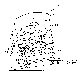
10 in which a carriage-body inclination device 30 is used. The
carriage 10 comprises a dolly 18 having wheels 16 and 17 which rotate
14
CA 02834995 2013-11-01
on rails 14 and 15 provided on a road surface 12, a carriage body
20 used by passengers or the like, air springs 22 and 23 provided
between the dolly 18 and the carriage body 20, and link lever
mechanisms 24 and 25 provided between the dolly 18 and the carriage
body 20. For one carriage, air springs and corresponding link lever
mechanisms are provided on the front, rear, left, and right sides,
but in FIG. 1, only two air springs 22 and 23 and two link lever
mechanisms 24 and 25 on the left and right are shown. Here, elements
of the carriage-body inclination device 30 will be briefly described,
and the detailed and specific structures will be explained later
with reference to FIG. 3 and subsequent drawings.
[0028]
In FIG. 1, the road surface 12 is inclined and there is a
difference in height between the left and right rails 14 and 15.
This difference is given to incline the carriage body 20 so that,
when the rails are provided in a curved shape and the carriage
travels on the curve, the passengers in the carriage body 20 do
not feel the centrifugal force. A height difference between the
rail 14 on the inner side of the curve and the rail 15 on the outer
side of the curve is referred to as an amount of cant. The amount
of cant is set according to the set velocity of the carriage
traveling on the curved portion. Therefore, for a carriage
traveling at a high velocity greater than or equal to the set
velocity, an excessive centrifugal force would be created.
[0029]
In order to prevent the passengers in the carriage body 20
from feeling the excessive centrifugal force, the carriage body
20 may be inclined with respect to the dolly 18 toward the inner
side of the curve to correspond to the amount of cant corresponding
CA 02834995 2013-11-01
to the high-velocity traveling. Such a control to incline the
carriage body 20 with respect to the dolly 18 in this manner is
called carriage-body inclination control. The example
configuration of FIG. 1 shows that the air spring 22 is contracted
and the air spring 23 is extended, so that the carriage body 20
is inclined with respect to the dolly 18 with the side of the air
spring 22 of the carriage body 20 being lower.
[0030]
The link lever mechanisms 24 and 25 are mechanisms each having
a dolly-side arm having one end rotatably supported with respect
to the dolly 18, and a lever which is a carriage-body-side arm having
the other end rotatably supported with respect to the carriage body
20, and in which the other end of the dolly-side arm and the one
end of the carriage-body-side arm are rotatably connected to each
other. When the height position of the carriage body 20 with respect
to the dolly 18 changes, the link shapes of the link lever mechanisms
24 and 25 change, and the shape change is uniquely determined by
the height of the carriage body 20 with respect to the dolly 18.
Thus, for example, an inclination angle of the carriage-body-side
arm with respect to a reference surface of the carriage body 20
which is defined in advance may be used as a height correspondent
value corresponding to the height of the carriage body with respect
to the dolly. In this respect, the link lever mechanisms 24 and
are height detectors which can provide the height correspondent
25 values as the height values.
[0031]
The carriage-body inclination device 30 comprises individual
inclination units 112 and 113 provided corresponding to the air
springs 22 and 23, and a controller 110 that integrally controls
16
CA 02834995 2013-11-01
the plurality of individual inclination units 112 and 113. As the
individual inclination units 112 and 113 are structures symmetrical
in the left-and-right direction in the example configuration of
FIG. 1, in the following, the explanation will be given with respect
to the individual inclination unit 112 as the representative
structure.
[0032]
Using a height instruction value given by the controller 110
and a height difference which is a difference with respect to the
height value obtained by the link lever mechanism 24, the individual
inclination unit 112 drives a control valve 40 and a large-capacity
valve 170 having a larger flow capacity than the control valve,
so that sufficient supply or release of air with respect to the
air spring 22 can be achieved.
[0033]
On each of the control valve 40 and the large-capacity valve
170, a supply hole connecting section, a release hole opening
section, and a load hole connecting section are provided. A gas
supply source 32 of FIG. 1 is a gas source that is connected to
the supply hole connecting sections of the control valve 40 and
the large-capacity valve 170, and that supplies pressurized air.
The releasing is effected by opening the release hole opening
sections of the control valve 40 and the large-capacity valve 170
to the side of the atmosphere.
[0034]
The control valve 40 has a spool-sleeve mechanism, and
includes a two-layer three-way valve 78 having a supply port, a
release port, and a load port. Here, the sleeve is divided into
two layers or parts, and is divided into a control sleeve 90 and
17
CA 02834995 2013-11-01
a fixed sleeve 91. The fixed sleeve 91 is a housing of the
spool-sleeve mechanism, and corresponds to a sleeve of a typical
spool-sleeve mechanism. The control sleeve 90 is a member that is
slidably supported on the fixed sleeve 91 on an outer
circumferential side, and that slidably supports a spool 80 on an
inner circumferential side.
[0035]
The spool 80 is moved and driven by a spool actuator, and the
control sleeve 90 is moved and driven by the link lever mechanism
24 via a rotation-translation conversion mechanism 44. A state of
the spool 80 and a state of the control sleeve 90 are detected by
respective sensors. FIG. 1 shows a situation where an electrical
signal indicating the state of the control sleeve 90 is supplied
to a large-capacity-valve driving unit 150. A detailed structure
of the control valve 40 will be described later with reference to
FIGs. 2 and 3. An electrical signal indicating the state of the
spool 80 is supplied to the controller 110, as will be described
with reference to FIG. 2.
[0036]
The large-capacity-valve driving unit 150 is a circuit that
outputs an electrical signal corresponding to a difference between
a position of the spool 80 and a position of the control sleeve
90 as a drive signal to the large-capacity valve 170. The
large-capacity valve 170 is a valve having a sufficiently larger
flow capacity than a flow capacity of the two-layer three-way valve
78. For
example, the large-capacity valve 170 is a gas valve having
at least twice, more preferably a flow capacity of 5 to 10 times
the flow capacity of the two-layer three-way valve 78. Similar to
the two-layer three-way valve 78, as the large-capacity valve 170,
18
CA 02834995 2013-11-01
a spool-sleeve type three-way valve may be employed.
[0037]
A control valve path 42 is a load path connecting the load
hole connecting section of the control valve 40 and the air spring
22. A large-capacity valve path 172 is a large-capacity load path
connecting the load hole connecting section of the large-capacity
valve 170 and the air spring 22. As shown in FIG. 1, the control
valve path 42 and the large-capacity valve path 172 are merged with
each other and connected to the air spring 22. Therefore, the air
spring 22 can be supplied with the pressurized air from both the
control valve 40 and the large-capacity valve 170, and the air spring
22 can be opened to the atmosphere and the air can be released from
the air spring 22 via the control valve 40 and the large-capacity
valve 170.
[0038]
An on-off valve 174 provided on the supply hole connecting
section of the large-capacity valve 170 and an on-off valve 176
provided on a release hole opening section of the large-capacity
valve 170 are opened when the inclination control of the carriage
body is executed, so that the large-capacity valve 170 is operated.
[0039]
Next, a detailed structure of the control valve 40 will be
described with reference to FIGs. 2 - 4. In general, the control
valve 40 comprises a supply on-off valve 60, the two-layer three-way
valve 78, the rotation-translation conversion mechanism 44
corresponding to a control sleeve actuator, a spool actuator 120,
a control sleeve sensor 130, and a spool sensor 140. FIG. 2 is a
structural diagram of the overall control valve 40, FIG. 3 is a
partial detailed diagram of the supply on-off valve 60 and the
19
CA 02834995 2013-11-01
two-layer three-way valve 78, and FIG. 4 is a detailed diagram of
the rotation-translation conversion mechanism 44. In
these
diagrams, orthogonal X, Y, and Z axes are shown. An X direction
is the movement direction of the spool 80 and the control sleeve
90.
[0040]
The control valve 40 comprises three gas circulation holes
including a supply hole connecting section 52, a release hole
opening section 54, and a load hole connecting section 41, and three
signal connecting sections including a spool drive control port
128, a control sleeve sensor port 132, and a spool sensor port 146.
These structures are mounted on the housing of the control valve
40. The housing of the control valve 40 is obtained by connecting
housings of the constituting elements, because the control valve
40 is a combination of the plurality of constituting elements. Here,
the fixed sleeve 91 which is a housing of the two-layer three-way
valve 78 is taken as a representative housing, and will be called
the housing of the control valve 40.
[0041]
The supply hole connecting section 52 is a connecting hole
for supplying pressurized air from the gas supply source 32 to the
supply on-off valve 60. The release hole opening section 54 is an
open end connected to the release port of the two-layer three-way
valve 78 and opening to the atmosphere. The load hole connecting
section 41 is a connecting hole for connecting the load port of
the two-layer three-way valve 78 and the air spring 22. A suitable
filter may be provided on the supply hole connecting section 52
and the load hole connecting section 41. In addition, a suitable
muffler may be provided on the release hole opening section 54.
CA 02834995 2013-11-01
[0042]
The spool drive control port 128 is a connector unit for
connecting a signal line for transmitting a drive control signal
from the controller 110 to the spool actuator 120. The control
sleeve sensor port 132 is a connector for connecting a signal line
for transmitting an output signal of a resolver or the like which
is the control sleeve sensor 130 that detects the state of the
control sleeve 90 to the large-capacity-valve driving unit 150.
The spool sensor port 146 is a connector for connecting a signal
line for transmitting to the controller 110 an output signal of
a displacement sensor which is the spool sensor 140 for detecting
the state of the spool 80.
[0043]
FIG. 3 is a cross sectional diagram showing details of the
supply on-off valve 60 and the two-layer three-way valve 78. The
supply on-off valve 60 corresponds to the supply port in the
two-layer three-way valve 78, and is connected to the gas supply
source 32. The supply on-off valve 60 is closed with a movement
of the control sleeve 90 of the two-layer three-way valve 78 in
a +X direction and is opened with the movement of the control sleeve
90 in the -X direction, or the supply on-off valve 60 is opened
with the movement of the spool 80 of the two-layer three-way valve
78 in the +X direction and is closed with the movement of the spool
80 in the -X direction. FIG. 3 shows a situation when the two-layer
three-way valve 78 is in a neutral state.
[0044]
The supply on-off valve 60 comprises an on-off-valve body 61
forming a part of the housing of the control valve 40 and a disc
mechanism 64 placed to be stored in an internal space of the
21
,
CA 02834995 2013-11-01
on-off-valve body 61. The on-off-valve body 61 is a tubular member
having one end side connected to the supply hole connecting section
52 and the other end side connected to an on-off-valve end of the
fixed sleeve 91 which is a part of the housing of the two-layer
three-way valve 78. On the one end side of the on-off-valve body
61, a ring-shaped protrusion 63 is provided.
[0045]
The disc mechanism 64 is a bidirectional disc with a spring
that has circular discs on both sides and in which a coil spring
70 having a weak spring constant is attached between the discs.
More specifically, the disc mechanism 64 comprises a supply-side
disc 66 which is a disc on the side of the supply hole connecting
section 52, an on-off-valve disc 68 which is a disc on the side
of the two-layer three-way valve 78, and the coil spring 70 which
is an urging unit connecting the supply-side disc 66 and the
on-off-valve disc 68. The coil spring 70 applies an urging force
on the supply-side disc 66 and the on-off-valve disc 68 in a
direction away from each other.
[0046]
The supply-side disc 66 is a circular disk having a function
of a check valve which prevents a backf low when a pressure inside
the on-off-valve body 61 becomes higher than a supplied pressure,
and has an outer shape with a size which can block an opening
surrounded by the ring-shaped protrusion 63 provided on the one
end side of the on-off-valve body 61.
[0047]
The on-off-valve disc 68 is a disc having an outer shape with
a size which can block, in the neutral state, the on-off-valve-side
opening which is an opening which is surrounded by a ring-shaped
22
CA 02834995 2013-11-01
protrusion 98 provided on the on-off-valve end side of the control
sleeve 90. Because the on-off-valve disc 68 is urged by the coil
spring toward the other end side of the on-off-valve body 61, in
the neutral state of the control sleeve 90, the on-off-valve disc
68 is pressed on the protrusion 98 on the on-off-valve end side
of the control sleeve 90. In FIG. 3, a proximal portion 65 on the
on-off-valve end side is shown surrounded by a broken line.
[0048]
When the spool 80 and the control sleeve 90 are in the neutral
state, a ring-shaped protrusion 88 provided on the on-off-valve
end side of the spool 80 is also set to have the same position in
the X direction as the ring-shaped protrusion 98 of the control
sleeve 90, and, thus, in the neutral state, the on-off-valve disc
68 is at the same time pressed toward the protrusion 88 of the
on-off-valve end side of the spool 80. With this configuration,
in the neutral state, the opening surrounding by the protrusion
98 on the on-off-valve end side of the control sleeve 90 and the
opening surrounded by the protrusion 88 on the on-off-valve end
side of the spool 80 are both blocked. A surface 69 of the
on-off-valve disc 68 on the side of the two-layer three-way valve
78, a tip of the protrusion 98 of the control sleeve 90, and a tip
of the protrusion 88 of the spool 80 are configured such that these
elements can be contacted with each other in an airtight manner.
[0049]
The spool 80 of the two-layer three-way valve 78 is a shaft
member having a narrow shaft stem section having, when a +X direction
end which is one end side in the axial direction is the on-off-valve
end side, a release opening 82 on the on-off-valve end side, that
extends in the axial direction, and in which there is provided a
23
CA 02834995 2013-11-01
central hole 84 in which the other end is in communication with
the release hole opening section 54, and a central land section
86 having a larger outer size than the stem section. The release
opening 82 is an opening surrounded by the ring-shaped protrusion
88.
[0050]
The control sleeve 90 is a member that is slidably supported
on the fixed sleeve 91 on an outer circumferential side and that
slidably supports the spool 80 on an inner circumferential side.
The control sleeve 90 has, when the +X direction end which is one
end side in the axial direction is the on-off-valve end side, an
on-off-valve-side opening having a larger inner size than the outer
size of the on-off-valve end side of the spool 80 on the on-off-valve
end side, and has a guide hole that slidably supports the spool
80 in the axial direction in the inside of the control sleeve 90.
The on-off-valve-side opening is an opening surrounded by the
ring-shaped protrusion 98 on the on-off-valve end side. FIG. 3
shows a gap space 100 between the outer circumference of the spool
on the on-off-valve end side and the inner circumference of the
on-off-valve-side opening of the control sleeve 90.
[0051]
The control sleeve 90 has three openings along the axial
direction, one of which is a load hole 50. As described above, in
the combination of the supply on-off valve 60 and the two-layer
three-way valve 78, the pressurized air from the gas supply source
32 is supplied from the side of the supply on-off valve 60 in the
control sleeve 90. In this respect, a structure corresponding to
the supply hole is the gap space 100 of the proximal portion 65
on the on-off-valve end side. In addition, in the control sleeve
24
CA 02834995 2013-11-01
90, the air from the air spring is released to the atmosphere through
the central hole 84 of the spool 80. In this respect, a structure
corresponding to the release hole is also the gap space 100 of the
proximal portion 65 on the on-off-valve end side. A detailed
operation thereof will be described later with reference to FIGs.
6 - 9.
[0052]
Therefore, the control sleeve 90 having the structure as shown
in FIG. 3 has three openings along the axial direction on the outer
circumference, and one of the openings is the load hole 50. In the
neutral state, positions of the load hole 50 and the central land
section 86 of the spool 80 coincide, and the load hole 50 is in
a state of being closed by the central land section 86. The other
openings; that is, two openings 92 and 94, are in communication
with each other by a communication path 96. The two openings 92
and 94 are used to switch, with cooperation of the spool 80, the
control sleeve 90, and the supply on-off valve 60, between supplying
pressurized air to the load hole 50 connected to the air spring
22 and releasing the pressurized air to the atmosphere through the
load hole 50. A detailed operation of these will be described later
with reference to FIGs. 6 - 9.
[0053]
Referring again to FIG. 2, the control sleeve 90 is connected
to the link lever mechanism 24 via the rotation-translation
conversion mechanism 44 at the -X direction end. FIG. 4 is an
enlarged perspective view of this portion. FIG. 4 shows, with
regard to the link lever mechanism 24, a dolly-side arm 26, a lever
28 serving as a carriage-body-side arm, and a rotation connection
section 27 which rotatably connects the arms with each other.
CA 02834995 2013-11-01
[0054]
The rotation-translation conversion mechanism 44 has a
function of converting a rotational movement of the lever 28 due
to a change of shape formed by the dolly-side arm 26 and the lever
28 serving as the carriage-body-side arm according to the height
value into a translational movement of the control sleeve 90. With
this process, the control sleeve 90 is moved and driven in the axial
direction according to the height value. In this respect, the link
lever mechanism 24 and the rotation-translation conversion
mechanism 44 correspond to the sleeve actuator which moves and
drives the control sleeve 90.
[0055]
The rotation-translation conversion mechanism 44 comprises
a rotational structure 162 in which a central shaft 161 is rotatably
held in a casing 160 fixed on the housing of the control valve 40,
a decenter pin 164 placed decentered from the central shaft 161
of the rotational structure 162, and a guide groove 168 provided
on a guide plate 166 connected to the -X direction end of the control
sleeve 90.
[0056]
One end of the lever 28 is mounted on the central shaft 161
of the rotational structure 162. Because a guide plate 166 is
integral with the control sleeve 90, the guide plate 166 is moveable
only in the X direction. The guide groove 168 is a groove provided
along the Z direction, and has a groove width to receive the decenter
pin 164.
[0057]
A resolver serving as the control sleeve sensor 130 placed
inside the casing 160 detects a rotational angle of the rotational
26
CA 02834995 2013-11-01
structure 162. The rotational angle of the rotational structure
162 is converted into a displacement in the axial direction of the
control sleeve 90 by the rotation-translation conversion mechanism
44. Thus, the resolver serving as the control sleeve sensor 130
detects the rotational angle corresponding to the displacement of
the control sleeve 90 in the axial direction. An output signal of
the resolver serving as the control sleeve sensor 130 is transmitted
to a control sleeve sensor port 132 through a suitable signal line.
Alternatively, in place of the resolver, a rotation detection sensor
of other types may be employed. For example, an encoder may be
employed.
[0058]
Referring again to FIG. 2, a spool shaft 118 is a portion of
the spool 80 extending and protruding beyond the region of the
two-layer three-way valve 78 in the -X direction. The spool
actuator 120 mounted on the spool shaft 118 is a force motor of
a moving coil type which moves and drives the spool 80 in the axial
direction. A displacement sensor serving as the spool sensor 140
mounted on the tip of the spool shaft 118 is a differential
transformer type sensor that detects the displacement of the spool
80 in the axial direction.
[0059]
The spool actuator 120 comprises a drive arm 122 mounted on
the spool shaft 118 and having a tip opening in a cup shape, a coil
124 provided on a tip of the drive arm 122, and a permanent magnet
126 mounted on the housing of the control valve 40 and placed to
oppose the coil 124. A drive current signal is supplied from the
controller 110 via the spool drive control port 128 to the coil
124. By a cooperation action of a current flowing in the coil 124
27
CA 02834995 2013-11-01
by the drive current signal and a magnetic flux of the permanent
magnet 126, a drive force in the axial direction is given to the
drive arm 122, and, with this process, the spool 80 can be moved
and driven in the axial direction.
[0060]
The spool sensor 140 is a displacement sensor that detects
an amount of movement of the spool 80 in the X direction. FIG. 2
shows a differential transformer type structure as the spool sensor
140, but alternatively, a displacement sensor of a type other than
the differential transformer type may be employed. For example,
an optical displacement sensor, an electrostatic capacity
displacement sensor, or the like may be employed.
[0061]
FIG. 5 is a block diagram of the carriage-body inclination
device 30 having the above-described structure. A feedback loop
from the height value indicating the height between the dolly 18
and the carriage body 20 which changes by the air spring 22, through
the link lever mechanism 24, the rotation-translation conversion
mechanism 44, and the two-layer three-way valve 78, and returning
to the air spring 22 is a loop for the level adjustment control.
Here, when the actual height value h is deviated from a standard
height value 110 which is defined in advance and a height difference
value Ah is created, the relative positional relationship of the
control sleeve 90 with respect to the spool 80 changes, pressurized
air is supplied to the air spring 22 in an amount of Ql or the air
is released from the air spring 22 to the atmosphere in an amount
of Qi, and the carriage body 20 is raised or lowered in a manner
to change Ah toward zero. The other portions correspond to a block
diagram when an additional supply flow Q2 is supplied to the air
28
CA 02834995 2013-11-01
spring 22 in the inclination Control. In particular, a portion of
a broken line frame 171 corresponds to a block diagram of a portion
for realizing a large-capacity output using the large-capacity
valve 170.
First, a flow in the level adjustment control will be
described. Here, formally, the standard height value 110 which is
defined in advance is given as a height instruction value 200 from
the controller 110. When the height instruction value 200 is at
[0063]
In the link lever mechanism 24, the length of the dolly-side
90 along the axial direction is at the neutral position via the
rotation-translation conversion mechanism 44 when the actual height
value is at the standard height value h0. Therefore, when the height
value is at the standard height value ho, the positional relationship
20 between the control sleeve 90 and the spool 80 is at the neutral
position. Thus, as shown in FIG. 3, the load hole 50 of the control
sleeve 90 is closed by the central land section 86 of the spool
80. At the same time, the protrusion 88 at the +X direction end
of the spool 80 and the protrusion 98 at the +X direction end of
25 the control sleeve 90 are in close contact with the on-off-valve
disc 68 of the supply on-off valve 60 at a proximal portion 65 on
the on-off-valve end side. Therefore, no pressurized air is
supplied from the control valve 40 to the air spring 22, and the
air spring 22 is not opened to the atmosphere via the control valve
29
CA 02834995 2013-11-01
40.
[0064]
When there is an increase or a decrease in the number of
passengers and the actual height value changes from the standard
height value 1'10 by Ah, the above-described feedback loop for level
adjustment control is put into effect. Specifically, with the
height change Ah, the position of the control sleeve 90 in the axial
direction is changed via the link lever mechanism 24 and the
rotation-translation conversion mechanism 44. Because the spool
80 remains in the neutral position, the relative positional
relationship between the load hole 50 of the control sleeve 90 and
the central land section 86 of the spool 80 changes. A configuration
is employed in which, when Ada is positive, the control sleeve 90
moves with respect to the spool 80 such that the air is opened to
the atmosphere from the air spring 22 via the control valve 40.
That is, because the on-off-valve disc 68 is pushed at the same
time as the movement of the control sleeve 90 in the +X direction,
a gap through which pressurized air can pass is created at the land
section 86 and the protrusion 88 of the spool 80, and the pressurized
air in the air spring is released through the passage to the
atmosphere. With this process, the height difference value Ala is
reduced, and, accordingly, the movement of the control sleeve 90
is returned toward the neutral position. In this manner, the
feedback is applied via the link lever mechanism 24 to set the height
difference value Ah to zero.
[0065]
Next, a flow for the inclination control will be described.
When the carriage 10 is required to incline the carriage body 20
in order to compensate for insufficient cant, different set height
CA 02834995 2013-11-01
values are given to the air springs. For example, in the structure
of FIG. 1, the air spring 22 is given a set height value h1 and the
air spring 23 is given a set height value h2. The inclination control
is applied such that the actual height values are set at the set
height values h1 and h2. In the following description, a case will
be described in which the air spring 22 is given the set height
value h1. If the positional relationship between the carriage body
20 and the dolly 18 before the inclination control is started is
at a parallel state, the actual height value is at the standard
height value 110 and the control sleeve 90 is at the neutral position.
[0066]
When the set height value h1 is given from the controller 110
as the height instruction value 200, a drive signal for the spool
actuator 120 is generated at a servo amplifier 202. If the set
height value h1 is larger than the standard height value ho, the
position of the spool 80 in the axial direction is changed to extend
the air spring 22. Because the control sleeve 90 remains in the
neutral state, the relative positional relationship between the
load hole 50 of the control sleeve 90 and the central land section
86 of the spool 80 changes. A configuration is employed in which
the spool 80 moves with respect to the control sleeve 90 such that
pressurized air is supplied via the control valve 40 to the air
spring 22. That is, because the on-off-valve disc 68 is pushed at
the same time as the spool 80 moves in the +X direction, a gap through
which pressurized air can pass is created at the load hole 50 and
the protrusion 98 of the control sleeve 90, and the pressurized
air is supplied through the passage into the air spring 22.
[0067]
With this process, the height value is increased. When the
31
CA 02834995 2013-11-01
height value is increased, the control sleeve 90 is moved in the
axial direction via the link lever mechanism 24 and the
rotation-translation conversion mechanism 44, and a feedback
similar to that in the level adjustment control acts. The feedback
acts continuously until the central land section 86 of the spool
80 and the load hole 50 of the control sleeve 90 coincide. The
position of the central land section 86 of the spool 80 in the axial
direction is offset from the position when the height value is at
the standard height value ho, and is at a position corresponding
to the height value of the set height value h1. Therefore, the
control sleeve 90 moves in the axial direction until the actual
height value h is at the set height value h1. When the actual height
value h reaches the set height value h1, the positions of the load
hole 50 of the control sleeve 90 and the central land section 86
of the spool 80 coincide, supply of pressurized air from the control
valve 40 to the air spring 22 is stopped, and the movement of the
control sleeve 90 is also stopped.
[0068]
As described above, in the inclination control, the position
of the spool 80 in the axial direction is offset from the neutral
position corresponding to the standard height value 110 to a position
corresponding to the set height value h1. In correspondence to this
offset, the control sleeve 90 is moved and driven in the axial
direction and the actual height value is set at the set height value
h1. In other words, other than the position of the spool 80 in the
axial direction being offset, the feedback including the link lever
mechanism 24 similar to that in the adjustment control is used.
[0069]
In this control, the amount of flow of the pressurized air
32
CA 02834995 2013-11-01
supplied to the air spring 22 is limited by the supply flow Qi of
the control valve 40. Thus, in order to increase the supply flow,
the large-capacity valve 170 is used. A loop which uses the
large-capacity valve 170 will now be described. An electrical
signal which is output from the control sleeve sensor 130 included
in the rotation-translation conversion mechanism 44 receives
suitable amplification and signal conversion from a control sleeve
sensor amplifier 206. An output of the control sleeve sensor
amplifier 206 is subtracted at a subtractor 208 from an output of
the servo amplifier 202 produced by the height instruction value
200. With this subtraction process, a height difference value
which is a difference between the set height value 111 which is the
height instruction value 200 and the actual height value is
determined. The height difference value is a value based on the
electrical signal value.
[0070]
The height difference value is suitably amplified by a
pre-amplifier 210 of the large-capacity-valve driving unit 150,
and a necessary signal conversion is applied thereto, to obtain
a drive signal of the large-capacity valve 170 by a current booster
212. The large-capacity valve 170 is driven with the drive signal.
A supply flow Q2 of the large-capacity valve 170 is significantly
larger compared to the supply flow Qi of the control valve 40.
[0071]
An adder 204 merges the supply flow Qi of the control valve
40 and the supply flow Q2 of the large-capacity valve 170, and
specifically corresponds to a merging portion of the control valve
path 42 and the large-capacity valve path 172 of FIG. 1. With this
process, the pressurized air is supplied to the air spring 22 with
33
CA 02834995 2013-11-01
a significantly larger amount of flow compared to the case where
only the control valve 40 is used. For example, Q2 may be set to
be 5 times Qi, and, with the use of the large-capacity valve 170,
a supply flow (Qi + Q2) which is six times the supply flow Qi when
only the control valve 40 is used can be supplied to the air spring
22. In this manner, the rate of extension of the air spring 22 is
significantly quickened.
[0072]
When the air spring 22 extends with a total supply flow in
which the supply flow from the large-capacity valve 170 is added
and the height value changes, the feedback control is applied to
each of the control valve 40 and the large-capacity valve 170. For
the control valve 40, as described above, the control is applied
by a feedback loop of the link lever mechanism 24, the
rotation-translation conversion mechanism 44, the two-layer
three-way valve 78, and the air spring 22. For the large-capacity
valve 170, the control is applied by a feedback loop of the link
lever mechanism 24, the rotation-translation conversion mechanism
44, the control sleeve sensor 130, the control sleeve sensor
amplifier 206, the subtractor 208, the large-capacity-valve driving
unit 150, the large-capacity valve 170, the adder 204, and the air
spring 22.
[0073]
In the above, a case has been described in which the
pressurized air is supplied to the air spring 22, but the process
is similar when the air is released from the air spring 22.
[0074]
In FIG. 5, the loop of the spool sensor 140 and a spool sensor
amplifier 214 applies a position feedback for the movement and
34
CA 02834995 2013-11-01
driving of the spool 80. That is, the loop is a loop from the servo
amplifier 202 to which the height instruction value 200 is given,
via the spool actuator 120, the spool 80, the displacement detection
by the spool sensor 140, and suitable amplification and necessary
signal conversion by the spool sensor amplifier 214, and returning
to the servo amplifier 202, and the position of the spool 80 is
fed back to the drive signal of the spool actuator 120. With this
configuration, a position control of the spool 80 is stabilized
and precision is improved.
[0075]
The operation of the above-described structure, in particular,
the operation of the supply on-off valve 60 and the two-layer
three-way valve 78, will now be described in detail with reference
to FIGs. 6 - 9. FIGs. 6 and 7 are diagrams for explaining level
adjustment control. FIG. 6 is a diagram for a case where the
pressurized air is supplied to the air spring 22 because the actual
height value his lower than the standard height value 110, and FIG.
7 is a diagram for a case where the pressurized air is released
from the air spring 22 because the actual height value h is higher
than the standard height value 110. FIGs. 8 and 9 are diagrams for
explaining inclination control. FIG. 8 is a diagram fora case where
the pressurized air is supplied to the air spring 22 because the
actual height value h is lower than the set height value 111, and
FIG. 9 is a diagram for a case where the pressurized air is released
from the air spring 22 because the actual height value h is higher
than the set height value ill.
[0076]
FIG. 6 shows a case in the level adjustment control where the
actual height value h is lower than the standard height value ho=
CA 02834995 2013-11-01
This case corresponds to a case where the control sleeve 90 is moved
in the -X direction with respect to the spool 80 at the neutral
position by the link lever mechanism 24 and the rotation-translation
conversion mechanism 44. In this case, because the control sleeve
90 moves backward with respect to the spool 80, a gap is created
between the protrusion 98 of the control sleeve 90 and the
on-off-valve disc 68 at the proximal portion 65 on the on-off-valve
end side, and the pressurized air from the supply hole connecting
section 52 flows through the gap and into the gap space 100 between
the inner circumference of the control sleeve 90 and the outer
circumference of the spool 80. The pressurized air further flows
into the load hole 50 through the opening 92, the communication
path 96, and the opening 94, and through the opening at the -X
direction side created by a deviation of the positional relationship
between the central land section 86 of the spool 80 and the load
hole 50, and is supplied from the control valve path 42 to the air
spring 22.
[0077]
In this manner, by the supply hole connecting section 52 and
the air spring 22 becoming in communication with each other, the
pressurized air is supplied to the air spring 22 and the air spring
22 is extended. When the air spring 22 is extended, the height value
h is increased. When the height value h is increased, the control
sleeve 90 is returned in the +X direction with respect to the spool
80. When the height value h reaches the standard height value 110,
the positions of the central land section 86 of the spool 80 and
the load hole 50 of the control sleeve 90 coincide, and the
protrusion 98 on the tip of the control sleeve 90 becomes closely
in contact with the on-off-valve disc 68 of the supply on-off valve
36
CA 02834995 2013-11-01
60. With this process, the structure returns to the neutral state
as described with reference to FIG. 3, and the supply of pressurized
air from the supply hole connecting section 52 is stopped. In this
manner, the level adjustment control to return the actual height
value to the standard height value ho is automatically executed.
[0078]
FIG. 7 shows a case in the level adjustment control where the
actual height value h is higher than the standard height value 110.
This case corresponds to a case where the control sleeve 90 is moved
in the +X direction with respect to the spool 80 at the neutral
position by the link lever mechanism 24 and the rotation-translation
conversion mechanism 44. In this case, because the control sleeve
90 is protruded with respect to the spool 80, the on-off-valve disc
68 blocks the on-off-valve-side opening of the control sleeve 90
by the urging force of the coil spring 70 serving as the urging
unit of the supply on-off valve 60. Specifically, the on-off-valve
disc 68 is pressed to the ring-shaped protrusion 98 of the control
sleeve 90 in the proximal portion 65 on the on-off-valve end side.
With this process, the supply of pressurized air from the supply
hole connecting section 52 is blocked. In addition, with this
process, a gap is created between the on-off-valve end side of the
spool 80 and the on-off-valve disc 68, and thus, the release opening
82 of the spool 80 and the internal space between the inner
circumference of the control sleeve 90 and the outer circumference
of the spool 80 become in communication with each other. More
specifically, a gap is created between the ring-shaped protrusion
88 on the on-off-valve end side of the spool 80 and the on-off-valve
disc 68. With this process, the gap space 100 between the inner
circumference of the control sleeve 90 and the outer circumference
37
CA 02834995 2013-11-01
of the spool 80 and the release opening 82 of the spool 80 become
in communication with each other.
[0079]
The space becomes in communication with the load hole 50 from
the opening on the +X direction side crated by the deviation of
the positional relationship between the central land section 86
of the spool 80 and the load hole SO, and becomes in communication
with the air spring 22 from the control valve path 42. Therefore,
the air from the air spring 22 passes through the control valve
path 42, the load hole 50, the gap space 100, and the release opening
82, and is released via the release hole opening section 54 to the
atmosphere.
[0080]
Because the air spring 22 and the release hole opening section
54 become in communication with each other in this manner, the air
from the air spring 22 is released to the atmosphere, and the air
spring 22 is contracted. When the air spring 22 is contracted, the
height value h is reduced. When the height value h is reduced, the
control sleeve 90 is returned in the -X direction with respect to
the spool 80. When the height value h reaches the standard height
value 110, the positions of the central land section 86 of the spool
80 and the load hole 50 coincide, and the protrusion 88 at the tip
of the spool 80 becomes in close contact with the on-off-valve disc
68 of the supply on-off valve 60. With this process, the structure
returns to the neutral state of FIG. 3, and the release of air from
the air spring 22 is stopped. In this manner, the level adjustment
control to return the actual height value to the standard height
value ho is automatically executed.
[0081]
38
CA 02834995 2013-11-01
Next, the inclination control will be described. In the
inclination control, as described above, the inclination control
can be more quickly executed using the large-capacity valve 170.
The use of the large-capacity valve 170 is for quickening the
inclination control, but in the operation of the supply on-off valve
60 and the two-layer three-way valve 78, the only difference between
the large-capacity valve 170 and the control valve 40 is in the
magnitude of the amount of flow, and, thus, in the following
description, a configuration is described in which the
large-capacity valve 170 is not used and only the control valve
40 is used. In the following description, a configuration is
considered in which, before the inclination control is started,
the height value indicating the height between the dolly 18 and
the carriage body 20 is at the standard state and the control sleeve
90 is at the neutral state.
[0082]
FIG. 8 shows a case where the height value is set at a high
value in the inclination control. This case corresponds to a case
where the spool 80 is moved in the +X direction with respect to
the control sleeve 90 at the neutral position by the spool actuator
120. In this case, because the spool 80 protrudes with respect to
the control sleeve 90, a gap is created between the protrusion 98
of the control sleeve 90 and the on-off-valve disc 68 at the proximal
section 65 at the on-off-valve end side, and the pressurized air
from the supply hole connecting section 52 flows through the gap
into the gap space 100 between the inner circumference of the control
sleeve 90 and the outer circumference of the spool 80. The
pressurized air then passes through the opening 92, the
communication path 96, and the opening 94, and from the opening
39
CA 02834995 2013-11-01
on the -X direction side created by a deviation of the positional
relationship between the central land section 86 of the spool 80
and the load hole 50 to the load hole 50, and is supplied from the
control valve path 42 to the air spring 22.
[0083]
When the supply hole connecting section 52 and the air spring
22 become in communication with each other in this manner, the
pressurized air is supplied to the air spring 22, and the air spring
22 is extended. When the air spring 22 is extended, the height value
h is increased. When the height value h is increased, the control
sleeve 90 is moved in the +X direction with respect to the spool
80. When the height value h reaches the set height value h1, the
positions of the central land section 86 of the spool 80 and the
load hole 50 of the control sleeve 90 coincide, and the protrusion
98 of the tip of the control sleeve 90 becomes in close contact
with the on-off-valve disc 68 of the supply on-off valve 60. With
such a configuration, corresponding to the setting of the height
value, the supply of the pressurized air from the supply hole
connecting section 52 is stopped at a state in which the control
sleeve 90 and the spool 80 are offset in the +X direction as compared
with the neutral state described with reference to FIG. 3. In this
manner, the inclination control to set the actual height value to
the set height value h1 is automatically executed.
[0084]
FIG. 9 shows a case in the inclination control where the height
value is set at a low value. This case corresponds to a case where
the spool 80 is moved backward in the -X direction with respect
to the control sleeve 90 at the neutral position by the spool
actuator 120. In this case, the spool 80 is withdrawn with respect
CA 02834995 2013-11-01
to the control sleeve 90. In this configuration, the on-off-valve
disc 68 blocks the on-off-valve-side opening of the control sleeve
90. More specifically, the on-off-valve disc 68 is pressed on the
ring-shaped protrusion 98 of the control sleeve 90 at the proximal
portion 65 on the on-off-valve end side. With this process, the
supply of pressurized air from the supply hole connecting section
52 is blocked. Because a gap is created between the on-off-valve
end side of the spool 80 and the on-off-valve disc 68, the release
opening 82 of the spool 80 and the internal space between the inner
circumference of the control sleeve 90 and the outer circumference
of the spool 80 become in communication with each other.
Specifically, a gap is created between the ring-shaped protrusion
88 on the on-off-valve end side of the spool 80 and the on-off-valve
disc 68. With this process, the gap space 100 between the inner
circumference of the control sleeve 90 and the outer circumference
of the spool 80 and the release opening 82 of the spool 80 become
in communication with each other.
[0085]
The space becomes in communication with the load hole 50 from
an opening on the +X direction side created by the deviation of
the positional relationship between the central land section 86
of the spool 80 and the load hole 50, and becomes in communication
from the control valve path 42 to the air spring 22. Therefore,
the air from the air spring 22 passes through the control valve
path 42, the load hole 50, the gap space 100, and the release opening
82, and is released via the release opening 54 to the atmosphere.
[0086]
Because the air spring 22 and the release opening section 54
become in communication with each other in this manner, the air
41
CA 02834995 2013-11-01
from the air spring 22 is released to the atmosphere, and the air
spring 22 is contracted. When the air spring 22 is contracted, the
height value h is reduced. When the height value h is reduced, the
control sleeve 90 is returned in the -X direction with respect to
the spool 80. When the height value h reaches the set height value
h1, the positions of the central land section 86 of the spool 80
and the load hole 50 coincide, and the protrusion 98 of the tip
of the control sleeve 90 becomes in close contact with the
on-off-valve disc 68 of the supply on-off valve 60. With this
process, corresponding to the setting of the height value, the
release of the air from the air spring 22 is stopped at a state
in which the control sleeve 90 and the spool 80 are offset in the
-X direction compared to the neutral state described with reference
to FIG. 3. In this manner, the inclination control to set the actual
height value to the set height value h1 is automatically executed.
[0087]
In the above, a structure in which the supply on-off valve
60 and the two-layer three-way valve 78 are combined is described
as the control valve 40. The control sleeve 90 of the two-layer
three-way valve 78 has a structure having three openings on the
outer circumference along the axial direction, one being the load
hole and the other two openings not being a supply hole or a release
hole. Alternatively, a typical spool-sleeve type three-way valve
structure may be employed in which three land sections are provided
on the spool, and the supply hole, the load hole, and the release
hole are placed on the outer circumference of the control sleeve
along the axial direction.
[0088]
FIG. 10 is a diagram for explaining a basic structure of an
42
CA 02834995 2013-11-01
example configuration of a control valve 180 having such a structure.
A three-way valve 181 used herein comprises a fixed sleeve 182,
a control sleeve 184, and a spool 186. The spool 186 can be driven
in the axial direction by the spool actuator 120, and the control
sleeve 184 can be driven in the axial direction by the link lever
mechanism 24 and the rotation-translation conversion mechanism 44.
In the spool 186, three land sections are provided on a stem,
distanced from each other in the axial direction. In the control
sleeve 184, a supply hole 188, a load hole 190, and a release hole
192 are placed in order, on the outer circumference along the axial
direction, corresponding to the placement of the three land
sections.
[0089]
In the neutral state, the position of the load hole 190
coincides with the position of the central land section of the spool
186, and the central land blocks the load hole 190. The supply hole
188 and the release hole 192 are placed corresponding to the
positions of the front and rear stems of the central land section.
In addition, in the fixed sleeve 182, a supply port, a load port,
and a release port are provided corresponding to the supply hole
188, the load hole 190, and the release hole 192 of the control
sleeve 184. The control sleeve 184 can be moved in the axial
direction with respect to the fixed sleeve 182 within a predefined
movement range, and, in the movement range, the supply hole 188
is within the range of the supply port, the load hole 190 is within
the range of the load port, and the release hole 192 is within the
range of the release port.
[0090]
With the control valve 180 which uses the three-way valve 181
43
CA 02834995 2013-11-01
and having the structure of FIG. 10 also, the structure of the block
diagram explained with reference to FIG. 5 can be employed, and
the operations of FIGs. 6 - 9 can be effected.
[0091]
In the above, the movement and driving of the control sleeve
are described as being effected by the link lever mechanism in which
the shape changes according to the height value, and the movement
and driving of the spool are described as being effected by the
spool actuator. The set height value maybe changed by setting the
offset of the relative position of the spool and the control sleeve.
Therefore, the movement and driving of the spool may alternatively
be effected by the link lever mechanism in which the shape changes
according to the height value and the movement and driving of the
control sleeve may alternatively be effected by the control sleeve
actuator such as a force motor.
[Industrial Applicability]
[0092]
The carriage-body inclination device and two-layer three-way
valve for carriage-body inclination body according to the present
invention are used in a carriage in which the carriage body is
inclined with respect to a dolly by extending or contracting an
air spring provided between the dolly and the carriage body.
[Explanation of Reference Numerals]
10 CARRIAGE; 12 ROAD SURFACE; 14, 15 RAIL; 16, 17 WHEEL; 18 DOLLY;
20 CARRIAGE BODY; 22, 23 AIR SPRING; 24, 25 LINK LEVER MECHANISM;
26 DOLLY-SIDE ARM; 287 ROTATION CONNECTION SECTION; 28 LEVER; 30
CARRIAGE-BODY INCLINATION DEVICE; 32 GAS SUPPLY SOURCE; 40, 180
CONTROL VALVE; 41 LOAD HOLE CONNECTING SECTION; 42 CONTROL VALVE
PATH; 44 ROTATION-TRANSLATION CONVERSION MECHANISM; 50, 190 LOAD
44
CA 02834995 2013-11-01
HOLE; 52 SUPPLY HOLE CONNECTING SECTION; 54 RELEASE HOLE RELEASING
SECTION; 60 SUPPLY ON-OFF VALVE; 61 ON-OFF-VALVE BODY; 62 INTERNAL
SPACE; 63, 88, 98 PROTRUSION; 64 DISC MECHANISM; 65 PROXIMAL PORTION
ON ON-OFF-VALVE END SIDE; 66 SUPPLY-SIDE DISC; 67, 69 SURFACE; 68
ON-OFF-VALVE DISC; 70 COIL SPRING; 78 TWO-LAYER THREE-WAY VALVE;
80, 186 SPOOL; 82 RELEASE OPENING; 84 CENTRAL HOLE; 86 CENTRAL LAND
SECTION; 90, 184 CONTROL SLEEVE; 91, 182 FIXED SLEEVE; 92, 94
OPENING; 96 COMMUNICATION PATH; 100 GAP SPACE; 110 CONTROLLER; 112,
113 INDIVIDUAL INCLINATION UNIT; 118 SPOOL SHAFT; 120 SPOOL
ACTUATOR; 122 DRIVE ARM; 124 COIL; 126 PERMANENT MAGNET; 128 SPOOL
DRIVE CONTROL PORT; 130 CONTROL SLEEVE SENSOR; 132 CONTROL SLEEVE
SENSOR PORT; 140 SPOOL SENSOR; 142 MAGNETIC STRUCTURE SHAFT; 144
COIL; 146 SPOOL SENSOR PORT; 150 LARGE-CAPACITY-VALVE DRIVING UNIT;
160 CASING; 161 CENTRAL SHAFT; 162 ROTATIONAL STRUCTURE; 164
DECENTER PIN; 166 GUIDE PLATE; 168 GUIDE GROOVE; 170 LARGE-CAPACITY
VALVE; 171 BROKEN LINE FRAME (BLOCK DIAGRAM FOR LARGE-CAPACITY
OUTPUT); 172 LARGE-CAPACITY VALVE PATH; 174, 176 ON-OFF VALVE; 181
THREE-WAY VALVE; 188 SUPPLY HOLE; 192 RELEASE HOLE; 200 HEIGHT
INSTRUCTION VALUE; 202 SERVO AMPLIFIER; 204 ADDER; 206 CONTROL
SLEEVE SENSOR AMPLIFIER; 208 SUBTRACTOR; 210 PRE-AMPLIFIER; 212
CURRENT BOOSTER; 214 SPOOL SENSOR AMPLIFIER.