Note: Descriptions are shown in the official language in which they were submitted.
CA 02835271 2013-11-06
- 1 -
PIPELINE FOR CARRYING A MOLTEN SALT
Description
The invention is based on a pipeline for carrying a molten salt, with a pipe
wall that is stable
with respect to the temperatures occurring.
Pipelines through which a molten salt flows are intended for use in solar
power plants, for ex-
ample, particularly parabolic-trough solar power plants. The pipelines are in
this case connect-
ed into networks, which serve for collecting solar energy in the solar power
plant. In such a
solar power plant, the radiant energy of the sun is concentrated by means of
parabolic mirrors
onto receivers. The combination of a parabolic mirror and a receiver is known
as a collector. A
row of collectors is connected in series to form solar loops. The radiation
energy collected by
the receivers is transferred to a heat transfer fluid. At present, a biphenyl-
diphenyl ether mix-
ture is used in particular as the heat transfer fluid, which however is
limited in its maximum
operating temperature by its decomposition temperature of about 400 C. To
obtain higher op-
erating temperatures, making greater efficiency possible, other heat transfer
fluids are re-
quired. Particularly used for this purpose are molten salts, for example that
known as solar
salt, a mixture of sodium nitrate and potassium nitrate in a ratio of 60:40.
However, a disadvantage of molten salts is that they have a high melting
point. For example, a
sodium-potassium nitrate mixture melts in the eutectic system, that is to say
in a mixing ratio of
44:56, at a temperature of 218 C. In long pipeline networks, as occur in solar
power plants, it
is difficult to operate reliably with molten salts that have high melting
points. The freezing of the
molten salt in pipeline systems can cause great commercial losses. The losses
are caused, for
example, by the great volumetric expansion of molten salts when they melt.
There is the risk of
fittings and pipelines being subjected to pressure and greatly damaged.
When the molten salt freezes, which mainly takes place at times when the solar
power plant is
not operating, i.e. at times when the sun is not shining, there may be a
volumetric contraction,
which may lead to a different state of solidification, depending on the
pipeline assembly and
the operating state. It is likely that bubbles which are generally evacuated
will occur in the
CA 02835271 2013-11-06
- 2 -
pipeline and come together to form units of varying sizes. When remelting
occurs, if there hap-
pens to be a great spatial distance between the locations where melting occurs
with volumetric
expansion and the evacuated regions, there may not be sufficient volumetric
equalization to
reduce the pressures occurring.
In order to prevent freezing of the molten salt, it is customary at present to
drain the pipeline
system during prolonged downtimes. Alternatively, it is also possible to heat
the pipeline sys-
tem. For this purpose, electrical energy or heat from available heat
reservoirs may be used for
example. If heat from available heat reservoirs is used, usually a hot heat
transfer fluid is
pumped through the pipeline system. These methods have the disadvantage that
considerable
amounts of energy in the form of electrical energy or in the form of thermal
energy have to be
consumed for this.
If electrical heating is provided, this is usually realized at present by
laying along with the pipe-
lines highly temperature-resistant mineral-insulated electrical heating
conductors. This tech-
nique cannot be used, however, in the case of solar receivers such as are used
in parabolic-
trough solar power plants, since the individual receivers are thermally
insulated very well from
the surroundings by an evacuated glass casing. At present, receivers are
therefore electrically
heated by a current of high intensity being applied at a low voltage to the
pipeline system itself.
This has the disadvantage, however, that varying transfer resistances or
thermal losses may
occur at the pipeline connectors. There is an increased occurrence of
electrical heat at the
locations with a high resistance. Then there is the risk of heating not being
uniform and the
temperature locally failing to reach the melting temperature of the salt that
is used as the heat
transfer medium.
Internal heating conductors are known and widely used, for example in
Scandinavia for the
frost protection of water pipeline systems. In this case, an insulated
electrical heating conduc-
tor is loosely laid in the pipeline system to be protected. When there is the
risk of frost, the
heating conductor prevents the pipelines from freezing. This method is
thermally more efficient
than heating from the outside. However, such heating conductors placed into
the pipeline can-
not be used for pipelines carrying molten salt. Apart from the much higher
operating tempera-
ture and the oxidizing conditions of a molten salt, the internal conductor in
water systems pro-
.
CA 02835271 2013-11-06
- 3 -
vides protection from volumetric expansion during freezing. As a difference
from this, however,
the volumetric expansion of molten salts does not occur during freezing but
during melting.
In particular before operation commences, it is necessary to heat the pipeline
system that is
carrying the salt. If, for this purpose, a voltage is applied to the pipeline
system itself, it is nec-
essary before the solar power plant is put into operation to bring the entire
steel mass of the
pipeline system to a temperature well above the melting point of the salt. A
great amount of
energy is required for this purpose.
In order to handle solar power plants with long pipelines without the molten
salt solidifying, it is
being attempted at present to use salts that melt at a lower temperature as an
alternative to
solar salt. This has the disadvantage, however, that the salts have a lower
thermal stability and
restrict the operating range to temperatures below 500 C. This leads to lower
efficiency of the
solar power plant in comparison with solar salts.
It is also necessary to keep the lower-melting heat transfer salts within
closed systems, which
causes additional expenditure since inerting systems have to be laid in the
solar array. Inerting
is necessary in particular whenever nitrite-containing mixtures are used as
the heat transfer
salt, since, in the presence of air, the nitrite can oxidize with oxygen to
form nitrate, and con-
sequently the solidification of the salt can rise in an uncontrolled manner.
If calcium-containing
salt mixtures are used, the calcium may react with carbon dioxide that is
contained in the air to
form insoluble calcium carbonate.
Furthermore, the addition of nitrates of the elements lithium, rubidium and
cesium may cause
the melting point of solar salt to be lowered. However, these salts are only
obtainable on a
small scale and are not available cost-effectively in the amounts such as are
required for solar
power plants, particularly those with heat reservoirs.
It is an object of the invention to provide a pipeline for carrying a molten
salt that allows heat
transfer salt that has solidified in the pipeline to melt again without
causing damage to the
pipeline. It is a further object to reduce the heat dissipation of a solar
array when it is not in
CA 02835271 2013-11-06
- 4 -
operation, for example overnight, by lowering the operating temperature of the
heat transfer
salt.
The object is achieved by a pipeline for carrying a molten salt, with a pipe
wall that is stable
with respect to the temperatures occurring, a heating conductor being provided
inside the pipe-
line for heating, the heating conductor not lying against the inner wall of
the pipeline.
The use of a heating conductor inside the pipeline makes it possible for salt
that has solidified
along the heating conductor within the pipeline to be melted uniformly, so
that there forms
around the heating conductor a channel through which molten salt can be
transported away.
This avoids excessive pressures being exerted on the pipeline as a result of
the volumetric
expansion of the molten salt. A uniform temperature distribution along the
heating conductor
also has the effect that the salt around the heating conductor melts at the
same time over the
entire length of the pipeline, and so there also forms a channel through which
the molten salt
can flow and thus the pressure can be equalized.
The pipeline according to the invention through which a heating conductor is
passed is used in
particular in the case of solar power plants, for example parabolic-trough
solar power plants. In
such solar power plants, the pipelines generally run substantially
horizontally, i.e. with a gradi-
ent of less than 5 , usually of less than 1 .
Individual pipelines in such a solar power plant each have sections that are
free from curvature
with a length of at least up to 100 m, usually up to 300 m. The large straight
sections make it
possible to place a heating conductor in the pipe without it having to be
passed through bends.
In a preferred embodiment, the heating conductor is arranged off-center in the
pipe, the dis-
tance of the heating conductor in the downward direction being greater than in
the upward di-
rection in the case of pipeline section running with a maximum gradient of 45
. Laying the
heating conductor off-center in the pipe avoids the heating conductor touching
the inner wall of
the pipeline as a result of sagging regions of the heating conductor between
two points of at-
tachment if there is a temperature-induced linear expansion of the heating
conductor. Also in
the case of sagging, it is necessary that the heating conductor does not have
direct contact
CA 02835271 2013-11-06
- 5 -
with the inner wall of the pipeline. To attach the heating conductor, it is
possible, for example,
for it to be passed through eyelets in the pipeline through which the molten
salt flows.
In the case of a gradient of more than 450, in particular in the case of
vertically running pipeline
sections, it is preferred if the heating conductor runs centrally in the
pipeline.
To avoid the heating conductor that has become extended in its length as a
result of the high
temperature being carried along with the molten salt, and in particular
tensioned at the begin-
ning of the pipeline, seen in the direction of flow, it is preferred to apply
an insulator to the
heating conductor, and so attach the heating conductor with the insulator in
the eyelet. This
ensures that the heating conductor is always attached at the same location in
the eyelet. It
avoids the heating conductor being pulled through the eyelets as a result of
the flowing molten
salt. This in turn makes it possible to avoid tearing of the heating conductor
caused by stresses
occurring during cooling, when the heating conductor contracts again. The
contraction of the
heating conductor may lead to problems in particular if the part that is
carried along when the
molten salt solidifies is fixed in the solidified salt and the heating
conductor can no longer
move.
As an alternative to attachment of the heating conductor by an eyelet, it is
also possible for the
heating conductor to be attached by resilient spacers inside the pipe. Here it
is preferred in
particular to attach the heating conductor in each case by at least three,
preferably four, spac-
ers in the pipe wall, which are attached to the heating conductor in a
crosswise manner. The
spacers may be attached to the pipe wall, for example, releasably by screws or
unreleasably
by a welded connection. It is preferred, however, not to connect the spacers
to the pipe wall. In
this case, the conductor is fixed inside the pipeline by the spacers in
addition to the eyelets.
In a further alternative embodiment, the heating conductor is provided with
loops, which are
suspended in attachment hooks in order to attach the heating conductor in the
pipeline. Provi-
sion of the loops achieves a way of attaching the heating conductor that
avoids the heating
conductor being displaced by the flowing molten salt. The loops may be
attached to the heat-
ing conductor, for example, by welding. For this purpose, it is possible, for
example, to draw
over the heating conductor a sleeve, which is welded to the heating conductor,
and to provide
CA 02835271 2013-11-06
- 6 -
the loops on the sleeve. Apart from welding onto the sleeve, it is also
possible to use a clamp-
ing sleeve, which is, for example, clamped together with the heating
conductor.
In order, when the salt melts, to form as quickly as possible a channel
through which the mol-
ten salt can flow, it is preferred to design the heating conductor in the form
of a tube or a chan-
nel of any desired cross section and to provide the wall of the tube or the
channel with open-
ings through which molten salt can flow into the interior of the heating
conductor designed in
the form of a tube or channel and be transported inside the heating conductor.
Apart from a solid outer wall which is provided with openings, it is
alternatively also possible for
the heating conductor to be designed, for example, as an annular knit or
weave. Also in this
case, a hollow space through which already molten salt can flow is formed
inside the weave or
knit.
As an alternative to designing the heating conductor as a hollow body inside
which there is
formed a channel through which the molten salt can flow, it is also possible
for the heating
conductor to have at least one u-shaped or v-shaped depression extending in
the axial direc-
tion. The salt will melt first in the depression, so that the depression forms
a channel through
which the molten salt can flow. A heating conductor with more than one u-
shaped or v-shaped
depression may, for example, have a star-shaped cross section. It is also
possible, for exam-
ple, for such a heating conductor to be designed in the form of a channel with
a u-shaped
cross section.
Apart from a hollow body or a heating conductor which has at least one u-
shaped or v-shaped
depression, it is also possible furthermore, for example, to provide a solid
electrical conductor
which has a wire mesh wrapped around it. In this case, the molten salt may
flow first in the
wire mesh, before a channel surrounding the heating conductor has formed
outside the wire
mesh.
Apart from the aforementioned possibilities, it is of course also possible for
the heating conduc-
tor to be a solid wire or be designed in the form of a cable. The heating
conductor may also be
formed from a material of good electrical conductivity, for example copper or
aluminum, which
CA 02835271 2013-11-06
- 7 -
is enclosed by a corrosion-resistant casing. This avoids corrosion of the
material of good elec-
trical conductivity in the presence of the salt that flows through the
pipeline, causing the heat
transfer salt to be contaminated and lose its thermal resistance.
Furthermore, it is also possible to use a conventional conductor, for example
with a current-
carrying core and electrical insulation, as the internal heating conductor a
corrosion-resistant
casing being additionally applied to the electrical insulation. A protective
metal casing as a
corrosion-resistant casing may in this case also serve as a return conductor
for the current.
Alternatively, a two-core arrangement with an insulated outer casing of high-
grade steel can
also be used. Such insulated heating conductors may also lie against the wall
of the pipeline.
If a stiff conductor, for example a rigid rod, is used, one or more expansion
regions are provid-
ed to allow compensation for expansions caused by temperature fluctuations
during operation.
An advantage of using a stiff conductor is that it requires fewer holders
within the pipeline sys-
tern than a flexible conductor, such holders preventing displacement in the
direction of flow.
The conductor may also be made up of segments, for example one segment per
receiver,
which are connected to one another in an electrically conducting manner during
assembly, for
example by screwing, welding or clamping. The segmental construction also
offers a concept
for replacing a receiver within a row by cutting and re-connection. The
connections must be
designed in such a way that sufficiently low transfer resistances are
realized.
If the heating conductor takes the form of a cable, one or more stranded
conductors are twist-
ed to form a cable. The cable preferably comprises multiple stranded
conductors. The twisting
of the stranded conductors to form a cable produces an interstitial channel in
the middle of the
cable, through which already molten salt can flow and can thus equalize the
pressure. Twisting
a cable with a stranded conductor can produce a spiral winding which has an
interstitial chan-
nel in its middle. A further advantage of using a cable is that the horizontal
compensation for
the thermal expansion can be made easier. Moreover, it is possible to set the
stiffness of the
conductor by the kind of stranding, so that, with corresponding twisting, the
cable has a
strength approaching the strength of a rigid conductor. This allows a smaller
number of holders
that secure the cable against displacement in the direction of flow to be
provided.
CA 02835271 2013-11-06
- 8 -
The stranded conductors from which the cable is twisted may take the form of
wires, that is to
say be solid, or else take the form of tubes. If the stranded conductors take
the form of tubes
and are not filled with highly electrically conductive material or a flowing
heat transfer medium,
" 5 they are respectively closed at the ends, preferably by welding.
The individual tubes are pref-
erably filled with a gas, for example air. The gas in the tubular stranded
conductors has the
effect of increasing the ascending force in the molten salt. This allows a
reduction in the hold-
ing force of the springs required for fixing near the middle of the tube. The
lowest descending
forces occur when the mean density of the tubular stranded conductors
corresponds to the
density of the molten salt of 1800 kg/m3. The tubular stranded conductors may
have a circular
cross section or a non-circular cross section. A non-circular cross section
is, for example, an
oval or elliptical cross section. In the case of a non-circular cross section,
it is possible that
locally occurring increased forces during the melting of the salt can be
elastically absorbed
better. Moreover, non-circular cross sections have the effect of increasing
the cross section of
the interstice, and thereby facilitate the pressure equalizing flow in the
interstitial channel. In
order to obtain a non-circular cross section, it is possible for example to
produce tubes for
forming the stranded conductors and flatten them, for example by rolling. A
further possibility
for forming a stranded conductor with a non-circular tube is a kidney-shaped
cross section.
The kidney-shaped cross section, which is obtained for example by the
compressive twisting of
round tubes over a round forming mandrel, has the effect of creating a
particularly large inter-
stitial channel between the stranded conductors. Since the stranded conductors
are accom-
modated in a molten salt, it is advantageous to subject the mechanically
deformed parts to
stress-free annealing in order to minimize the risk of corrosive attack.
In the case of a tubular design of the stranded conductors, it also possible
as an alternative or
in addition to the electrical heating to use a liquid or gaseous heat transfer
medium which flows
through the tubular lines.
If the pipeline is used as a pipeline in a solar array of a parabolic-trough
solar power plant, the
pipeline usually comprises an inner pipe, through which the molten salt flows,
and an outer
casing of glass. The intermediate space between the inner pipe and the outer
casing of glass
is evacuated. The surface of the inner pipe is usually designed so as to
absorb the solar radia-
CA 02835271 2013-11-06
- 9 -
tion and to be heated up in this way. The heat is then transferred from the
inner pipe to the
heat transfer medium that is flowing through the pipes. These regions are
generally also
known as receivers.
In a solar power plant, the pipelines usually run in a u-shaped manner, one
leg of the pipeline
being connected to an inflow and a second leg being connected to an outflow.
The legs of the
pipeline extend without curvature over a distance of usually at least 100 m,
preferably over at
least 300 m. On the side opposite from the inflow and the outflow, the two
legs are connected
to one another by way of a crossing piece of pipe. The molten salt then flows
via a bend into
the crosspiece and from the bend into the parallel lying second pipeline,
forming the second
leg. In a preferred embodiment, the pipe bends for flow deflection each have a
pipeline section
that continues in the direction of the pipeline, the pipeline section being
closed by a closure
and the heating conductor being passed through the closure of the pipeline
section. In order
that the pipeline is not subjected to any stress during the operation of the
insulated heating
conductor, the heating conductor is usually passed through the closure of the
pipeline with an
insulation. The insulation serves at the same time for sealing.
The closure of the pipeline section may be configured, for example, as a blind
flange. Any oth-
er desired cover that withstands the pressure occurring in the pipelines may
also be used.
However, a blind flange is preferred.
Irrespective of the type and form of the heating conductor, a round rod is
preferably attached to
the end of the heating conductor. This rod may be connected to the heating
conductor, and
connected in an insulating or non-insulating manner to the pipeline, for
example by a welded
connection, a screwed connection or a clamped connection. The connection must
in this case
be designed such that the round rod is connected to the heating conductor with
good electrical
conductivity. If the closure of the pipeline section is a blind flange, to
obtain attachment for ex-
ample in an electrically insulating or non-insulating manner the round rod is
guided and at-
tached in a stuffing-box construction. In order to prevent electric current
being conducted to the
pipes in the case of the insulated heating conductor, the stuffing-box packing
of the stuffing-
box construction is configured in an electrically insulating manner. The
stuffing-box packing
achieves a gap between the round rod and the lead-through of the heating
conductor into the
CA 02835271 2013-11-06
- 10
pipeline. A low voltage of up to 0.7 V may be applied over the gap. In spite
of the low voltage,
there is a high electric field strength in the gap and in the vicinity of the
gap. This high electric
field strength brings about a current flow to and over the pipeline wall if
the pipeline system is
filled with electrically conducting molten salt.
Complete electrical insulation of the internal conductor inside the pipeline
near its lead-in, for
example by means of the blind flange, prevents an undesired current flow. The
electrical insu-
lation may be built up for example in the region of a stuffing box or in the
region of a flat gas-
ket. If a flat gasket is used, electrically insulated screwed unions must also
be used.
Since materials used for electrical insulation are generally not resistance to
the temperatures
which prevail inside the pipelines as a result of the molten salt that has
melted, it is possible to
produce a temperature gradient by suitable thermal insulating materials. For
example, it is
possible to include a fibrous material for thermal insulation in the region of
the blind flange in
the pipeline. A quartz fiber weave may be used for example as the fibrous
material. The round
rod to which the heating conductor is attached is passed through an
electrically insulating and
high-temperature resistant sleeve, for example made of ceramic or silicon
carbide. The first
sleeve of ceramic or silicon carbide is adjoined by a second electrically
insulating sleeve,
which no longer has to be resistant to such high temperatures.
Polytetrafluoroethylene (PTFE)
or other high-temperature plastic is suitable for example as the material for
the second sleeve.
The two electrically insulating sleeves are enclosed by a further sleeve,
which ends in a flange.
The flange is closed by an electrical insulation with a second flange. A
stuffing box which is
sealed with a seal is used for leading the round rod through the closing
flange. The insulating
materials that are used have the effect that the temperature in the region of
the stuffing box is
so low that the seal can be produced from a standard material.
If the solidified salt in the pipeline is to be melted, the heating conductor
may only produce a
small amount of heat in the region of the lead-in in order not to put at risk
the formation of a
temperature gradient. This can be achieved, for example, by the heating
conductor having a
lower electrical resistance in the region of its lead-in into the pipeline
than in the actual heating
zone. The lower electrical resistance can be achieved, for example, by the
round rod into
which the heating conductor opens being configured with a greater diameter
than the heating
CA 02835271 2013-11-06
- 11 -
conductor in the heating zone. As an alternative and in addition, the heating
conductor may
comprise a material with particularly good electrical conductivity in the
region of the lead-in into
the pipeline, in order to avoid heating up of the heating conductor in the
region of the lead-in
into the pipeline. A suitable material with good electrical conductivity is,
for example, copper or
aluminum. In the region of the lead-in, the heating conductor may be produced
here complete-
ly or partially from the material with good electrical conductivity. For
example, it is possible to
design the heating conductor in the region of the lead-in such that it
comprises a solid copper
core.
As an alternative to a round rod, a rod with a different cross section may
also be used. Howev-
er, a round rod is preferred.
The internal conductor may also be installed in the pipeline system in a non-
insulated manner.
In this case, the lead-in may not include any insulating measure. This is of
advantage in partic-
ular whenever, for example, individual pipeline sections of a solar loop are
not connected to
another by flange connections but are welded to one another. Then it is no
longer possible to
control the electrical resistance of the entire pipeline by insulation of the
individual pipeline
sections. If the heating conductor is not electrically insulated from the
pipeline sections welded
to one another, application of a voltage causes currents to flow through the
individual pipeline
sections and the internal conductor with a ratio which is proportional to the
ratio of the conduc-
tivity of the pipeline to the conductivity of the heating conductor.
Corresponding to the ratio,
heat is generated on the pipeline and on the heating conductor. By choosing an
adequate
cross section of the heating conductor and choosing material with very good
electrical conduc-
tivity for the heating conductor, for example copper or aluminum, the
resistance of the heating
conductor can be lowered and the conductivity increased to such an extent that
the current is
led into the internal conductor sufficiently strongly and the development of
heat is concentrated
on the heating conductor provided inside the pipeline to such a degree that
the internal heating
conductor is heated up more quickly than the pipeline. It is conducive for
quicker heating up of
the internal conductor that the pipeline has a generally much greater mass,
and consequently
much higher heat capacity, than the internal conductor.
CA 02835271 2013-11-06
- 12 -
In the case of such an arrangement with an uninsulated heating conductor, no
potential differ-
ences between the heating conductor and the pipeline occur over the entire
pipeline. The pipe-
line can be electrically insulated with respect to the apparatus framework
that carries the pipe-
line.
In order that the heating conductor is not damaged by the molten salt flowing
through the pipe-
line, it is preferably produced from a material that is corrosion-resistant
with respect to the salt
used, in particular with respect to nitride. Alternatively, it is possible, as
already described
above, to provide the heating conductor with a corrosion-resistant casing. If
the heating con-
ductor is produced from a corrosion-resistant material, high-grade steel is
particularly suitable,
for example preferably the steels of the type St 1.4571 and St 1.4541, but
also St 1.4301 or
nickel-based steels such as St 2.4856.
If a high-grade steel, for example St 1.4571, is used, there initially forms
on the heating con-
ductor a passivating, corrosion-inhibiting metal oxide/nitride film about 15
pm thick, which of-
fers an appreciable resistance to the current flow. The resistance of the
protective layer helps
in controlling the potential of the heating conductor system. Even small
electrical voltages on
conductive salts can trigger electrode processes that lead to corrosive
deposits. Electrode pro-
cesses may commence from a certain limit voltage. The corrosion-inhibiting
protective layer
causes protection by overvoltage and thus increases the decomposition voltage
of the system.
Use of the heating conductor inside the pipeline allows command to be
maintained over high
melting points of the heat transfer medium used in the pipeline. This opens up
the possibility of
also using as the heat transfer medium salt mixtures which have a higher
melting point then
salt mixtures previously discussed. For example, nitrate mixtures which
comprise sodium ni-
trate as the main component may be used. This has the advantage that potassium
reserves
that can be used for the production of potash fertilizers can be largely
spared. Currently, "Solar
Salt 60" comprises 60% by weight sodium nitrate and 40% by weight potassium
nitrate. The
proportion of sodium nitrate in the salt can be increased to 80% by weight or
even to over 90%
by weight and more. The melting point of the salt increases accordingly from
235 C in the case
of a mixture of 40% by weight potassium nitrate and 60% by weight sodium
nitrate to 273 C in
the case of a mixture of 80% by weight sodium nitrate and 20% by weight
potassium nitrate
CA 02835271 2013-11-06
- 13 -
and to 293 C in the case of a mixture of 90% by weight sodium nitrate and 10%
by weight po-
tassium nitrate. If pure sodium nitrate is used, the melting point is at 306
C.
Apart from the stoichiometric composition of the molten salts, the internal
conductor has great
advantages in connection with these molten salts. The solidified high-melting
crystals are
heavier than the surrounding molten salt and sink to the bottom of the
pipeline. The sinking
rate for large crystallites is greater than for small crystallites. Attachment
of the crystallites to
the pipe wall and the covering thereof is conceivable, but has not been
observed so far in well-
insulated pipes. If the pipes have a gradient, high-melting crystallizate
becomes separated at
the lower-lying points. The extent of the separation depends here on the
quality of the insula-
tion of the pipeline. Very well-insulated pipelines in which the melt
solidifies slowly over a long
period of time may exhibit greater separation than less well-insulated
pipelines.
However, the sinking, high-melting crystals do not succeed in completely
displacing low-
melting melt. Rather, in the lower-lying regions of the pipelines there forms
an accumulation of
high-melting crystallites, though still with low-melting material in their
interstices. When solidify-
ing is complete, there forms from this an inhomogeneous mixture of
crystallites with different
melting temperatures.
If this mixture is heated, initially the crystallites with the low melting
point melt. The melt ob-
tained first completely wets the composite structure of the crystallites with
a higher melting
temperature. The two-phase mixture obtained initially loses scarcely any of
its mechanical sta-
bility. Only when part of the supporting crystallite composite structure with
a higher melting
temperature melts does the mixture go over into a pumpable form. For use in
solar power
plants, this means that pipelines with solidified molten salt in them must be
heated beyond the
intended melting point - in the case of Solar Salt 60 of 242 C - before
innocuous pumpability
can be achieved.
By selective crystallizing of crystallites containing a high proportion of
sodium nitrate and sink-
ing thereof to lower-lying regions of the pipeline, the remaining molten
sodium nitrate is deplet-
ed. This depletion even continues until the eutectic concentration ratio is
reached in the melt.
CA 02835271 2013-11-06
- 14 -
At this concentration ratio, the residual melt in the upper region of the
pipeline system then
solidifies.
Use of the heating conductor inside the pipeline allows economical and
reliable melting of such
solidification morphologies to be accomplished.
Particularly in the case of horizontal pipeline routing, the heating conductor
can be specifically
placed in the upper region of the pipeline. There it is surrounded by a
mixture of crystallites
which has an increased proportion of crystallites with a low melting
temperature, that is those
of the eutectic system. In addition, a multiplicity of voids can be found in
the upper region of
the pipeline. A melt channel can be created relatively easily there, possibly
reducing horizontal
differences in pressure that occur during heating up.
On account of the solidification morphology, for example of Solar Salt 60 as
described above,
it is scarcely possible to define meaningful melting points for a molten salt
of a salt mixture. For
instance, melting already begins at a temperature of 221 C, but the last
crystals only disap-
pear at a temperature above 280 C.
Since, along with the actual pipeline section, the pipeline usually also
comprises fittings, for
example valves, it is necessary also to heat the valves correspondingly in
order to ensure their
function and also not to destroy them by expansion of the molten salt during
melting. In order
to heat a valve, it is possible for example to heat the region of the static
closing element direct-
ly from the internal heating conductor, and thereby to melt the salt in the
valve. In this case, the
heating conductor is connected directly to the static closing element from
both sides of the
valve. If resistance matching is required there, a good electrical conductor
in the form of a ring
may be placed around the static closing element. The ring is in this case
preferably fitted in the
valve body in such a way that it does not weaken load-bearing parts of the
valve construction.
As a result of the electrical insulation with respect to the valve body, heat
of the heating con-
ductor that is released is concentrated on the seat of the valve.
Alternatively, it is also possible
to produce a ring from a material with very good electrical conductivity, for
example copper.
The heating ring in the valve is preferably made to match in its resistance
value the value of
the heating conductor. Here, the ring forms part of the heating conductor in
the region of the
CA 02835271 2013-11-06
- 15 -
valve. Apart from using a valve, an analogous construction with other fittings
can be used, for
example in the case of flaps or slides. The ring in that case respectively has
the geometrical
form of the lead-through through which the molten salt flows.
Exemplary embodiments of the invention are explained in more detail in the
description which
follows and are represented in the figures, in which:
Figure 1 shows a schematic representation of a solar array of a
parabolic-trough solar pow-
er plant,
Figure 2 shows a pipeline section with frozen molten salt,
Figure 3 shows a section through a pipeline with Solar Salt 60
solidified in it,
Figure 4 shows an example of how a heating conductor runs in a solar loop,
Figure 5 shows a pipeline section with a heating conductor running in
it,
Figure 6 shows the effect of a flow through the pipe on an unattached heating
conductor,
Figure 7 shows an attachment of a heating conductor with an insulator in
an eyelet,
Figure 8 shows attachment of a heating conductor with a loop on a hook,
Figure 9 shows formation of a channel in the solidified salt along the
heating conductor,
Figure 10 shows attachment of a heating conductor in the region of a pipe bend
for flow de-
flection,
Figure 11 shows how the internal conductor is provided at an end piece with a
180 bend,
Figure 12 shows an alternative form of pipeline routing angled away at 90 ,
CA 02835271 2013-11-06
- 16 -
Figure 13 shows a cross section through a pipeline section with a number of
segments,
Figure 14 shows how parasitic currents pass between the heating conductor and
the pipe
wall,
Figures 15A show cross sections of different heating conductor geometries,
to 15E
Figure 16 shows a stiff heating conductor with expansion compensation,
Figure 17 shows a cross section through a pipeline with a heating conductor
held by resilient
spacers,
Figure 18 shows a section through the pipeline along the line A-A' in Figure
17, and
Figure 19 shows a section through the pipeline along the line B-B' in Figure
17,
Figure 20 shows a heating conductor formed as a cable and completely
uninsulated in a long
pipeline of welded pieces of pipeline,
Figure 21 shows a heating conductor formed as a cable with a lead-through
through a blind
flange,
Figures 22A
to 22C show cross sections of different heating conductors formed as a
cable,
Figure 23 shows an alternative lead-through of a heating conductor through a
blind flange,
Figure 24 shows how a heating conductor is provided in a movable pipe
connection,
Figure 25 shows a cross section through a valve with a heating conductor
provided in it,
CA 02835271 2013-11-06
- 17 -
Figure 26 shows a section through the valve from Figure 25 in plan view.
=
Figure 1 shows a schematic representation of a solar array of a parabolic-
trough solar power
plant.
A solar array 1 of a parabolic-trough solar power plant has a number of solar
loops 3. The so-
lar loops 3 are each formed by a pipeline 5, through which a heat transfer
medium flows. Used
according to the invention as the heat transfer medium is a molten salt,
preferably solar salt,
i.e. a mixture of potassium nitrate and sodium nitrate in a ratio of 40:60, or
as a eutectic sys-
tem with a mixing ratio of 44:56.
In the solar loops 3, the heat transfer medium is heated by means of
irradiating solar energy.
For this purpose, the pipelines 5 are segmentally enclosed by a glass tube 7.
The space be-
tween the pipeline 5 and the glass tube 7 is evacuated. Underneath the glass
tubes 7 there is
also a parabolic trough, in which irradiating sunlight is reflected and
directed onto the glass
tube 7. The incident radiation on the glass tube 7 causes heat to be conducted
to the heat
transfer medium that flows through the pipeline 5, as a result of which the
heat transfer medi-
um is heated up.
The heat transfer medium flowing through the pipelines 5 of the solar loops 3
flows into a col-
lector 9 and from the collector 9 on into a heat transfer outflow 11. The heat
transfer medium
flowing through the heat transfer outflow 11 is usually made to pass into a
heat exchanger, in
which the latter gives off heat to a steam circuit, which is used for example
to operate turbines
for power generation. The cooled heat transfer medium leaving the heat
exchanger is made to
pass via a heat exchanger inflow 13 into a distributor 15 and from the
distributor 15 into the
pipelines 5 of the solar loops 3.
On account of the high melting point of a molten salt, said salt generally
solidifies when the
solar power plant is not being operated. This is always the case, for example,
whenever too
little sunlight irradiates the parabolic troughs, for example at night.
Operation must also be
suspended, for example, when maintenance work has to be carried out.
CA 02835271 2013-11-06
- 18 -
During inoperative times, the molten salt flowing through the pipelines 5 may
solidify. This is
shown in Figure 2 by way of example for a pipeline section.
When the molten salt solidifies in the pipeline 5, there is generally a
volumetric contraction.
This has the effect that evacuated bubbles 17 are produced in the pipeline 5.
The evacuated
bubbles 17 are in this case located within the solidified salt 19.
If it is attempted to melt the solidified salt, it is possible that, if there
happens to be a great spa-
tial distance between the locations where melting occurs with volumetric
expansion and the
evacuated bubbles 17, there may not be sufficient volumetric equalization to
reduce the pres-
sures occurring. The volumetric expansion caused by the melting of the salt
may then result in
the pipeline 5 been damaged.
The morphology of solidified Solar Salt 60, that is to say a salt mixture of
60% by weight sodi-
um nitrate and 40% by weight potassium nitrate, is shown by way of example in
Figure 3.
When Solar Salt 60 solidifies, initially crystallizate enriched with sodium
nitrate and having a
melting temperature of about 280 C solidifies at about 244 C. The sodium
nitrate forms crys-
tallites which sink downward within the pipeline section 47. Here, the sinking
rates is depend-
ent, inter alia, on how large the crystallites become. The size of the
crystallites depends on the
solidifying rate. On account of the sinking of the crystallites of sodium
nitrate, the concentration
of crystallites decreases upwardly within the pipeline section 53. On account
of the volume
contraction of the salt, isolated voids form within the solidified salt 19. On
the surface of the
solidified salt 19 forms a foam-like region 20, in which the eutectic
composition of the Solar
Salt 60 is solidified. This region generally does not comprise any sodium
nitrate crystallites.
Above the foam-like region 20 there forms an evacuated bubble 17. The
crystallizate accumu-
lates in the lower regions of the region of the pipeline that is accessible to
flow. Voids form with
preference in upper regions of the region that is accessible to flow.
CA 02835271 2013-11-06
- 19 -
In order to obtain uniform melting of the molten salt within a pipeline 5,
according to the inven-
tion a heating conductor 21 with a uniform resistivity is laid through the
pipeline 5. This is
shown by way of example in Figure 4.
According to the invention, the heating conductor 21 is provided inside the
pipeline 5. The
heating conductor is in this case formed, for example, as an electrical
resistance wire. If a volt-
age is applied, the heating conductor 21 heats up and the salt surrounding the
heating conduc-
tor 21 melts to form a channel surrounding the heating conductor 21.
The heating conductor 21 is supplied by way of a main voltage supply 23. A
supply line 25 for
the heating conductor 21 branches off from the main voltage supply 23. In a
transformer 27,
the supply voltage is transformed to the voltage necessary for heating the
molten salt in the
pipeline 5. It is possible to connect a number of heating loops to one voltage
supply. The volt-
age supply is connected to the loops one after the other and the loops are
heated up one after
the other.
To make simple assembly of the heating conductor 21 possible, it is preferably
led out of the
pipeline 5 at the end of one leg of the pipeline 5 running in a u-shaped
manner and is connect-
ed in an electrically conducting manner to the heating conductor that is led
out from the second
leg. This makes it possible to avoid complex laying, in particular in the case
of movable collec-
tor pipelines 5, which require many supports for the heating conductor 21.
It is particularly preferred to use for the heating an electrical heating
circuit with a floating alter-
nating potential, which is generated by an ungrounded transformer 27. A
floating alternating
voltage offers advantages in terms of safety. For instance, an insulating
fault in a loop can be
tolerated.
The receivers themselves must be held in an electrically insulated manner. The
receivers must
also be insulated with respect to one another. A resistance of the insulator
that is greater than
the resistance of the heating conductor by a factor of 10 is generally
sufficient. For example,
on the basis of the preferred small resistance of the heating conductor of
less than 0.1 f) over
a receiver, a resistance of one ohm is generally already adequate for
sufficient insulation. The
CA 02835271 2013-11-06
- 20 -
insulating state of the heating conductor may, for example, be monitored by an
online re-
sistance measurement.
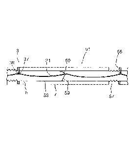
A pipeline section with a heating conductor running in it is shown in Figure
5.
The heating conductor 21 is attached in the pipeline 5, for example, in a
suspended manner,
as shown in Figure 5. For this purpose, it is possible, for example, to pass
the heating conduc-
tor 21 through eyelets 29. The eyelets 29 are in this case attached, for
example, in a suspend-
ed manner on the upper side of the pipeline 5.
The heating conductor 21 is preferably provided off-center in the pipeline 5,
the distance from
the upper side of the pipeline 5 being chosen smaller than the distance from
the underside of
the pipeline 5. The off-center laying of the heating conductor 21 avoids the
heating conductor
21 coming into contact with the pipe wall during heating, and accompanying
linear expansion.
The sagging of the heating conductor 21 is in this case strongly dependent on
the temperature.
The higher the temperature, the greater the linear expansion, and the greater
the heating con-
ductor 21 sags.
Apart from the attachment with eyelets 29 shown in Figure 5, it is
alternatively also possible,
for example, to use resilient spacers. The resilient spacers are in this case
preferably arranged
in a crosswise form in the pipeline 5 and the heating conductor 21 is provided
at the intersec-
tion of the cross.
A further advantage of the off-center arrangement of the heating conductor 21
in the upper
region of the pipeline 5 is also that the evacuated bubbles 17 usually occur
in the upper part of
the pipeline 5. During the heating up of the heating conductor 21 and the
accompanying melt-
ing of the salt in the pipeline 5, a liquid channel is quickly formed along
the heating conductor
21. Through this channel that is formed, pressures that may occur due to
volumetric expansion
during the melting can be dissipated to the evacuated bubbles 17, acting with
a relieving effect.
If the heating conductor 21 is not attached in the eyelets 29, this may have
the effect, however,
that the heating conductor 21 is carried along by the molten salt flowing
through the pipeline 5
CA 02835271 2013-11-06
- 21 -
until it is tensioned in the pipeline 5. This is shown by way of example in
Figure 6. Only at the
end, i.e. directly upstream of a fixing point of the heating conductor 21,
there forms a large loop
31, which may possibly also touch the pipeline 5.
A further disadvantage of the tensioning of the heating conductor 21 with the
formation of the
loop 31 is that, in the event of the molten salt solidifying, such a
displacement of the conductor
can lead to very great mechanical loading of the heating conductor 21, with
subsequent me-
chanical damage. The heating conductor is fixed in its position when the salt
solidifies and be-
gins to shrink on account of the decreasing temperature of the molten salt. As
a result, strong
tensile forces act on the already tensioned part of the heating conductor 21.
In order to avoid such displacement of the heating conductor 21, it is
preferably axially fixed in
the pipeline 5.
Possible fixing of the heating conductor 21 is shown by way of example in
Figures 7 and 8.
Attachment of a heating conductor in an eyelet with an insulator is shown in
Figure 7.
For the attachment of the heating conductor 21, it is possible, for example,
to provide the heat-
ing conductor 21 with an insulating sleeve 33. The insulating sleeve 33 is in
this case connect-
ed to the heating conductor 21 in such a way that the insulating sleeve is not
displaceable. For
this purpose, it is possible, for example, to clamp the insulating sleeve 33
onto the heating
conductor 21. Alternatively, it is also possible, for example, to connect the
insulating sleeve 33
to the heating conductor 21 releasably, for example by screwing, or
unreleasably, for example
by welding.
The insulating sleeve 33 has a widening 35 on one side. For the attachment of
the heating
conductor 21 in the pipeline 5, the heating conductor 21 is passed with the
insulating sleeve 33
applied to it through an eyelet 29 attached in the pipeline 5. The insulating
sleeve 33 then lies
with the widening 35 against the eyelet 29, so that the insulating sleeve 33
cannot slip through
the eyelet 29. To avoid slipping through while operation is in progress, the
widening 35 is posi-
tioned on the side of the eyelet 29 against which the heat transfer medium
flows.
CA 02835271 2013-11-06
- 22 -
If it is intended to reverse the flow or operate the solar loop 3 in such a
way that the heat trans-
fer medium can flow in any direction, it is alternatively also possible to
provide a further widen-
ing on the side opposite from the widening 35 once the heating conductor 21
has been passed
through the eyelet 29.
An alternative attachment of the heating conductor 21 is shown in Figure 8.
In the case of the embodiment shown in Figure 8, a loop 37 is provided on the
heating conduc-
tor 21. The loop 37 is suspended in a hook 39, which may, for example, be of a
spiral design,
as shown in Figure 8. The spirally designed hook 39 has the effect of avoiding
the loop 37 be-
coming detached while operation is in progress as a result of differing flow
influences.
The loop 37 may, for example, be attached on the heating conductor 21 by means
of a sleeve
41. The sleeve 41 is, for example, in this case a clamping sleeve that is
connected to the heat-
ing conductor 21. The attachment of the sleeve 41 may take place, for example,
by clamping
or by welding or screwing.
It is particularly preferred if the sleeve 41 and/or the loop 37 are produced
from an insulating
material.
The use of an insulating sleeve 33, such as that shown in Figure 7, or a loop
37 and a sleeve
41 of an insulating material has the advantage that no current flow takes
place from the heat-
ing conductor 21 to the sleeve 29 or the hook 39. In this way, parasitic
currents that flow via
the attachment of the heating conductor 21 to the pipeline 5 can be reduced.
Formation of a channel in the solidified salt along the heating conductor is
shown in Figure 9.
If the salt in the pipelines 5 has solidified after an unwanted inoperative
time of the solar power
plant, for example when no power is generated at night, to resume operation
the heating con-
ductor 21 is first supplied with a voltage, whereby it is heated up. Around
the heated-up heat-
ing conductor 21, the salt contained in the pipelines 5 begins to melt. If
there is a uniform cur-
CA 02835271 2013-11-06
- 23 -
rent flow in the heating conductor 21, the salt melts uniformly, and there
forms a channel 43.
The molten salt can flow through the channel 43, whereby pressures occurring
on account of
the increase in volume can be reduced as the salt melts.
Avoiding a buildup of pressure by allowing the salt to flow through the
channel 43 has the ef-
fect of avoiding damage to the pipelines 5 when the solar power plant is put
into operation.
Use of the heating conductor 21 also makes it possible to dispense with
draining the pipelines
5, and consequently the entire solar array 1, when there is an unwanted
inoperative time. It is
also unnecessary to completely prevent the salt from solidifying as an
alternative to draining
the pipelines 5. The heating conductor must merely keep a sufficiently large
flow channel free.
In addition, the internal heating conductor offers great advantages when
restarting after drain-
ing of the loop. On the one hand, flow can be admitted to the pipeline system
when only the
heating conductor but not the pipeline system has reached a temperature well
above the melt-
ing point. On the other hand, the uniform resistivity over the entire length
of the heating con-
ductor ensures an absence of cold spots.
Attachment of a heating conductor in the region of a pipe bend for flow
deflection is shown by
way of example in Figure 10.
-
As can be seen from Figure 1, a solar loop 3 is usually designed in a u-shaped
manner. For
this purpose, two pipelines 5 form the legs of the u-shaped solar loop 3, the
pipelines 5 that
form the legs being connected to one another on the side facing away from the
collector 9 or
distributor 15 by way of a crossing pipe. The molten salt flows through one
leg of the u-shaped
solar loop 3, then via the crossing piece of pipeline connecting the two legs
and back to the
collector 9 through the second pipeline 5. To avoid complex assembly of the
heating conductor
21 in the region of the flow deflection of the molten salt at the end of the
legs, it is advanta-
geous to design a pipe bend 45 that is used for the flow deflection as a T
piece and to provide
it with a pipeline section 47 that continues in the direction of the pipeline
5. The pipeline sec-
tion 47 is closed by a closure 49, and the heating conductor 21 is passed
through the closure
49.
CA 02835271 2013-11-06
- 24 -
Suitable, for example, as the closure 49 for the pipeline section 47 is a
blind flange.
To avoid a flow of current to the pipeline 5 via the pipeline section 47, the
heating conductor 21
is passed through the closure 49 in an insulated manner. The heating conductor
21 passed
through the closure 49 can then be connected to a suitable supply of
electrical potential. It is
alternatively also possible, as shown in Figure 4, for two heating conductors
of two adjacent
pipelines 5 to be respectively connected to one another.
A deflection of the molten salt over 1800 through two pipe bends, as shown in
Figure 10, is
shown in Figure 11.
To make it possible for the inside of the pipe to be heated, first a heating
conductor 21 is
passed along the pipeline 5 in an insulated manner through the closure 49. A
pipeline section
121 that is turned by 90 is connected to the pipeline 5. A heating conductor
21 is likewise
passed through the pipeline section 121 that is turned by 90 . In order to
supply current to the
heating conductor 21 both in the pipeline 5 and in the pipeline section that
is turned by 90 , the
ends of the respective heating conductors that are passed in an insulated
manner through the
closures 49 are in electrical contact with one another through an external
conducting arrange-
ment 119.
In the same way, the pipeline section 121 that is turned by 90 is adjoined by
a second pipe-
line 5, which is likewise turned by 90 with respect to the pipeline section
121 that is turned by
90 , so that altogether a deflection of 180 is achieved. At this point too,
the heating conductor
21 is respectively passed through the closure 49 of the ends of the pipeline
and electrically
connected to one another through an external conducting arrangement 119, so
that all the
lengths of line through which the molten salt flows can be heated altogether
by one heating
conductor 21 lying inside.
An alternative form of pipeline routing angled away at 90 is shown in Figure
12. The heating
conductor 21 is held in the middle of the pipe by a clamping device 122. The
clamping device
122 is attached to the bend in the heating conductor 21 by clamping or
welding. This construc-
.
CA 02835271 2013-11-06
- 25 -
tion makes it possible for the internal heating conductor to follow the
direction of flow of the
heat transfer medium. In comparison with the embodiment shown in Figure 11, it
does not
have a pipeline connector or the external conducting arrangement.
A cross section through a pipeline section with a number of segments is shown
in Figure 13.
A solar loop 3 of a solar power plant is generally divided into a number of
segments 51. Each
of the segments 51 has a pipeline section 53, which is enclosed by a glass
tube 7. The respec-
tive segments 51 each serve in this case as a receiver for capturing the solar
energy.
The individual pipeline section 53 are usually produced from a metal with good
electrical con-
duction, for example from high-grade steel. In order locally to limit possible
parasitic currents
from the heating conductor 21 to the pipeline 5, it is preferred to separate
the individual pipe-
line sections 53 from one another by insulators 55. A material which has a
greater resistance
than the resistance of the heating conductor used as heating conductor 21 is
chosen as the
material for the insulators 55. Heat-resistant ceramics, mineral-fiber seals
or mica seals are
suitable in particular as the material for the insulators 55.
In addition to the insulators 55, the individual segments 51 are connected to
one another by
way of mechanical connections or compensators 57. The mechanical compensators
57 are
necessary to compensate for linear expansions of the pipelines 5 during
operation.
Although the insulated heating conductor 21 may be attached by insulators
inside the pipeline
5, as shown by way of example in Figures 7 and 8, it is advantageous to place
some of the
insulators 55 shown in Figure 13 in a solar loop, in order to prevent fed-in
parasitic currents
from accumulating in the pipe system.
Apart from being used in the pipelines 5 of the solar loops 3, the heating
conductor 21 accord-
ing to the invention for the internal heating of a pipeline 5 may also be used
for heating the
collector 9, distributor 15, heat-transfer medium outflow 11 and heat-transfer
medium inflow 13
as well as all the other pipelines through which molten salt flows. If
flexible conductors are
used, use in flexible hose lines is also possible.
CA 02835271 2013-11-06
- 26 -
=
Since the resistance of a metal is generally temperature-dependent, it is also
possible further-
more to use the heating conductor 21 for measuring the average temperature of
the internal
heating conductor and also, indirectly, the molten salt in the pipeline 5.
This is particularly ad-
vantageous whenever a material which has a strong temperature dependence of
the conduc-
tivity is used for the heating conductor 21.
The attachment of the heating conductor 21 in the embodiment represented in
Figure 13 takes
place in each case at the beginning of a segment 51 with a loop 37 and a hook
39, as shown
in Figure 8. The attachment with the hook 39 means that the heating conductor
21 is secured
against displacement within the segment 51. The attachment of the heating
conductor 21 with-
in the respective pipeline section 53 takes place, for example, by way of
resilient spacers 59.
The attachment by resilient spacers may be provided here at one or more
positions in the
length of pipeline 53 of the segment 51. For assembly, the resilient spacers
59 are in this case
preferably pushed into the pipe and are not connected to the pipe wall but
only supported on
the pipe wall.
Highly heat-resistant steels, for example St 2.4668, or Inconel X750 are
preferred as the mate-
rial for the resilient spacers 59.
The passing of parasitic currents between the heating conductor and the pipe
wall is shown by
way of example in Figure 14.
In the case of non-insulated attachment of the insulated heating conductor 21,
for example
when resilient spacers 59 are used, a current flows via the resilient spacers
59 to the pipeline
5. This is represented by way of example by dashed arrows. The parasitic
currents 61 occur-
ring have the effect that heating power does not occur at the heating
conductor 21 but else-
where, for example on the wall of the pipeline 5. As long as the currents
through the heating
conductor 21 dominate, though parasitic currents 61 reduce the efficiency of
the heating they
do not put at risk the heating function of the heating conductor 21.
Apart from the parasitic current flow 61 via devices for attachment to the
pipe wall, a current
flow also occurs through the molten salt on account of the high conductivity
of the molten salt
CA 02835271 2013-11-06
- 27 -
in the pipeline 5. This is represented by way of example by arrows 63. If the
wall of the pipeline
is covered with solidified, low-conductivity salt, the current flow 63 through
the molten salt
largely stops.
5 If high-grade steel is used for the heating conductor 21, the parasitic
current flow 63 through
the molten salt is reduced by a passivating metal oxide/nitrate film about 15
pm thick usually
forming on the high-grade steel, the metal oxide/nitrate film offering an
appreciable resistance
to the current flow.
Furthermore, it is possible for the applied electrical voltage to cause
corrosion, owing to an
electrochemical reaction. For this reason, it must be ensured that the
electrical voltage lying
between the heating conductor 21 and the wall of the pipeline 5 lies below the
threshold poten-
tial at which an electrochemical reaction commences.
Examples of suitable heating conductor geometries are shown in Figures 15A to
15E.
The heating conductor 21 may, for example, be designed as a tubular cable, as
shown in Fig-
ure 15A. The heating conductor 21 is in this case preferably formed from a
steel mesh. During
the operation of the heating conductor 21 that is designed in the form of a
tubular cable 65, the
salt melts first inside the heating conductor 21, whereby there forms within
the heating conduc-
tor 21 a channel through which molten salt can flow. Salt surrounding the
heating conductor 21
that melts can flow into the inner channel 67 through openings in the mesh
that forms the tubu-
lar cable 65.
As an alternative to a tubular cable 65, as shown in Figure 15A, it is also
possible to design the
heating conductor 21 in the form of a tube 69. In this case, it is also
advantageous to provide
the tube with a perforation through which molten salt can flow into the
interior of the tube. The
way in which the heating conductor 21 shown in Figure 15B functions largely
corresponds in
this case to the way in which the heating conductor 21 shown in Figure 15A
functions.
In Figure 15C, a heating conductor with a star-shaped cross section is shown.
Such a star-
shaped cross section has v-shaped depressions 71. During the operation of the
heating con-
CA 02835271 2013-11-06
- 28 -
ductor 21, the salt begins to melt first in the v-shaped depressions 71, so
that in each of the v-
shaped depressions 71 there forms a channel through which the molten salt can
flow.
Apart from the embodiment as a five-pronged star shown in Figure 15C, any
other number of
v-shaped depressions and associated prongs is also possible. Apart from v-
shaped depres-
sions, it is alternatively also possible, for example, to provide u-shaped
depressions.
In Figure 15D, a heating conductor designed as a rod 73 is shown, the rod 73
being enclosed
by a mesh 75, preferably an electrically conductive wire mesh. During the
operation of a heat-
ing conductor that is designed as shown in Figure 15D, initially channels
through which the
molten salt can flow form in the mesh 75. Then there forms a channel
surrounding the heating
conductor 21.
The embodiments designed as shown in Figures 15A to 15D each require a heating
conductor
of a material that does not corrode in the presence of the molten salt flowing
through the pipe-
line 5. Such a material is, for example, high-grade steel, for example St
1.4571 or else St
1.4301.
However, high-grade steels have poorer current conduction than copper or
aluminum, for ex-
ample, which however generally corrode easily in the salt that is used. To be
able to use a
heating conductor of a material with better current conduction than high-grade
steel, it is pos-
sible, for example, to provide a core 77 of a material with good electrical
conductivity, for ex-
ample copper or aluminum, which is enclosed by a corrosion-resistant covering
79, as shown
in Figure 15E. The corrosion-resistant covering 79 may in this case also be,
for example, a
corrosion-resistant tube which is connected in a good heat-conducting manner
to the core 77.
This construction offers the option of operating the internal heating
conductor entirely without
electrical insulating measures in a pipeline.
A heating conductor with a cross-sectional geometry such as that shown in
Figures 15A to 15E
may be flexible or configured as a stiff conductor. If the heating conductor
21 is configured as a
stiff conductor, it is advantageous to provide expansion regions 81 to
compensate for changes
in length caused by temperature fluctuations. A stiff heating conductor with
expansion region
81 is shown by way of example in Figure 16. The expansion region 81 is in this
case designed
CA 02835271 2013-11-06
- 29 -
in a wave form. Apart from the wave-form design shown here, any other geometry
that makes
length compensation possible is suitable for the design of the expansion
region 81.
In Figures 17 to 19, a heating conductor which is held in a pipeline by
resilient spacers is
shown.
The resilient spacers 59 are preferably arranged in a crosswise manner.
Alternatively, howev-
er, it is also possible, for example, to provide only three resilient spacers
59, in this case one of
the resilient spacers 59 preferably being aligned perpendicularly. The
perpendicularly aligned
resilient spacer may in this case be arranged either below or above the
heating conductor 21.
One possibility for the attachment of the resilient spacers 59 to the heating
conductor 21 is
shown in Figure 18. For the attachment it is thus possible, for example, to
clamp the resilient
spacers 59 with a sleeve 83. For this purpose, the sleeve 83 is pushed over
the heating con-
ductor 21 and an end portion 85 of the resilient spacers 59. Additional
attachment is possible,
for example, by the sleeve 83 being welded to the heating conductor 21.
The end portion 87 of the resilient spacers 59 that is facing away from the
heating conductor is
preferably bent into a foot 89. The foot 89 may in this case be designed, for
example, in the
form of an eyelet. With the foot 89, the resilient spacer 59 is supported on
the wall of the pipe-
line. This is shown in Figure 19. The use of the resilient spacers 59, as they
are shown in Fig-
ures 17 to 19, serves for keeping the heating conductor 21 at a predetermined
height in the
pipeline 5. The fact that the resilient spacers 59 are only pressed against
the wall of the pipe-
line 5 by their spring pressure with their respective foot 89 means that it is
possible for the re-
silient spacers 59 to be moved with the flow of the molten salt in the
pipeline 5. It is therefore
preferred, as shown in Figure 13, to provide a holder for the heating
conductor 21, such as that
shown in Figures 7 and 8, at regular intervals, preferably at least once in
each receiver.
The positioning of the resilient spacers 59 just by pressing of the feet 89
against the wall of the
pipeline 5 has the advantage that the heating conductor 21 can, if need be,
easily be pulled
out of the pipeline 5 together with the resilient spacer 59. This may be
required, for example, in
the case of necessary maintenance.
CA 02835271 2013-11-06
- 30 -
Apart from the feet shown in Figure 19, it is also possible to design the end
portions 87 of the
resilient spacers 59 that are facing away from the heating conductor in any
other desired form
that allows retention in the pipeline 5.
Furthermore, it is also possible not just to hold the resilient spacers 59 in
the pipeline 5 by their
contact pressure, but to attach the resilient spacers 59 in the pipeline
releasably, for example
by screwing, or unreleasably, for example by welding.
In Figure 20 a long pipeline 5 comprising pipeline sections 53 connected to
one another by
welding, for example receivers of a solar loop, is shown. If the heating
conductor 21 is not
electrically insulated from the string of pipeline sections 53 welded to one
another and a volt-
age is applied, a current la flows through the string of lengths of pipeline
53 and a current I,
flows through the internal conductor, the ratio of the intensities of the
currents 1,/la being in the
ratio of the resistance of the pipeline 5 to the resistance of the heating
conductor 21. Corre-
sponding to the ratio, heat is generated on the pipeline 5 and on the heating
conductor 21. By
choosing an adequate cross section of the heating conductor 21 and choosing
materials with
very good electrical conductivity, for example copper or aluminum, the
resistance of the heat-
ing conductor 21 can be lowered to such an extent that the current is led into
the heating con-
ductor 21 sufficiently strongly and the development of heat is concentrated on
the heating con-
ductor 21.
In the arrangement shown here, no potential differences between the heating
conductor 21
and the pipeline 5 occur over the entire pipeline 5. The pipeline 5 should be
electrically insulat-
ed from the apparatus framework not shown here, by which the pipeline 5 is
carried.
In the case of the uninsulated internal heating conductor, the lead-in of the
heating conductor
21 into the space inside the pipe may be created simply by clamped/screwed
unions.
In Figure 21, a heating conductor formed as a cable with a lead-through
through a blind flange
is shown.
CA 02835271 2013-11-06
- 31 -
In the embodiment shown here, the heating conductor 21 takes the form of a
cable 91. The
cable 91 is in this case twisted from a number of stranded conductors 93.
Here, the cable may be produced for example from three stranded conductors, as
shown in
Figure 21, or else from one or two or more than three stranded conductors.
For the attachment of the heating conductor 21 formed as a cable 91 to an end
piece of a pipe-
line section 47, the cable 91 is connected to a round rod 95. The connection
of the cable 91 to
the round rod 95 is performed for example by a welded connection, or
alternatively also by
screwing or clamping. In the case of a clamped connection, the round rod 95 is
clamped onto
the cable 91. In the embodiment shown here, the cable 91 is connected to the
round rod 95 by
a welded connection 97.
The round rod 95 is led through a stuffing-box lead-through 99 through the
blind flange 101,
with which the pipeline section 53 is closed off. For the attachment of the
round rod 95, the
stuffing-box lead-through 99 comprises a stuffing box 103. This is braced with
a clamping
sleeve 105.
A voltage may be applied to the round rod 95 in order to supply voltage to the
heating conduc-
tor 21 formed as a cable 91.
In Figures 22A to 22C, cross sections of different heating conductors formed
as a cable are
shown.
The cables 91 shown in Figures 22A to 220 are in each case made up of three
stranded con-
ductors 93.
In Figure 22A, the stranded conductors 93 are of a solid configuration.
Between the individual
stranded conductors there forms an interstitial channel 107, through which the
melting salt can
flow away during remelting.
CA 02835271 2013-11-06
- 32 -
In the embodiment shown in Figure 22B, the stranded conductors 93 are formed
as flattened
tubes. The flattening has the effect that a larger interstitial channel 107
forms in comparison
with the embodiment shown in Figure 22A. An even larger interstitial channel
107 is obtained
in the case of the embodiment shown in Figure 22C, in which individual
stranded conductors
93 from which the cable 91 is twisted have a kidney-shaped design.
An alternative embodiment for leading the heating conductor through the end
length of a pipe-
line is shown in Figure 23.
In order to make the stuffing box with conventional materials, in particular a
sealing ring pro-
duced from a customary polymer material, it is necessary to realize a
temperature gradient
along the heating conductor and the round rod. The temperature gradient is set
by the end of
the pipeline 5 through which the round rod 95 is passed being insulated less
well. In addition,
the formation of a gradient may be assisted by an inner thermal insulation of
the lead-through
of the heating conductor 21. The inner thermal insulation can be realized, for
example, by us-
ing ceramic fibers which have a thermal resistance of, for example, up to 580
C. A corre-
sponding filling with ceramic fibers is denoted by reference numeral 109.
The round rod 95 is initially enclosed by a first sleeve of an electrically
insulating and tempera-
ture-resistant material, for example ceramic or silicon carbide. The first
sleeve 111 preferably
has a temperature resistance of up to 580 C.
The first sleeve 111 is adjoined by a second sleeve 113. The second sleeve 113
is produced
from a likewise electrically insulating material, which however may have a
lower temperature
resistance. For example, a temperature resistance up to 260 C is sufficient. A
high-
temperature plastic, such as PTFE, may be used for example as the material for
the second
sleeve 113.
The second sleeve 113 is then adjoined by the stuffing-box lead-through 99.
For this purpose,
the stuffing-box lead-through 99 is attached to a flange 115 at the end of the
pipeline.
CA 02835271 2013-11-06
- 33 -
The round rod 95 that is used preferably comprises a material with good
electrical conductivity.
Here it is possible to make the round rod completely from the material with
good electrical
conductivity, or alternatively to provide a core of a material with good
electrical conductivity
which is enclosed by a material with less good conductivity, for example
steel. Copper or alu-
minum are suitable, for example, as the material with good electrical
conductivity. Particularly
preferably, a round rod 95 with a copper core is used.
In Figure 24 it is shown how a heating conductor is provided in a movable pipe
connection.
Apart from a flow deflection as shown in Figures 10 and 11, it is
alternatively also possible, for
example, to provide a movable pipe connection for the flow deflection. Here, a
pipe bend 117
is produced from a flexible material. For this purpose it is possible, for
example, to design the
pipe bend in a wave form or a zigzag form in order to achieve the necessary
flexibility.
In order to be able to remelt the salt in the pipe bend 117 after it freezes,
it is also necessary to
provide a heating conductor 21 in the pipe bend 117. To avoid the heating
conductor coming
into contact with the walls of the pipe bend 117, the heating conductor 21 is
fixed in the pipe-
line, for example by a resilient spacer 59, as shown in Figures 17 and 18. The
spacing of the
individual resilient spacers 59 is chosen such that the heating conductor 21
does not come into
contact with the pipe wall even during bending of the pipe connection.
Apart from the deflection at the end of a solar loop, a movable pipe
connection such as that
shown in Figure 24 may also have been included for example between individual
solar receiv-
ers, in order to adapt the pipeline with the receivers respectively to the
optimum position in
relation to the sun.
If, in addition to the flexible pipe bend, a deflection by 90 is provided, as
shown in Figure 24, it
is advantageous to lead the heating conductor out of the pipeline from the
pipeline section 47
in a blind flange, for example as shown in Figures 21 and 23, and to connect
the heating con-
ductor at the end in an electrically conducting manner to an external
conducting arrangement
119. The pipeline section 121 that is turned by 90 likewise ends in a closure
49, which is con-
figured for example as a blind flange, and through which there is passed a
heating conductor
21, which is then led through the movable pipe connection.
CA 02835271 2013-11-06
- 34 -
Apart from deflection and movable pipeline sections, a pipeline usually also
comprises fittings,
for example valves. A cross section through a valve with a heating conductor
provided in it is
shown by way of example in Figures 25 and 26.
Figure 25 shows a cross section through a valve 123 with a heating conductor
21 provided in it
and Figure 26 shows a section through the valve from Figure 25 in plan view.
A valve usually comprises a valve body 125 with a valve seat 127 and a closing
element 129.
To be able to melt a solidified salt within the valve, the heating conductor
21 is provided along
the valve seat 127 in the form of a ring. This means that the heating
conductor forms a heating
ring 121. The heating ring 131 is in this case positioned such that the
closing function of the
valve 123 is not impaired. Moreover, a direct connection between the heating
ring 131 and the
closing element 129 should be avoided when the heating conductor 21 is
carrying a voltage.
For this reason, it is advantageous to provide an electrical insulation 133 on
the valve seat
127. In this case, the electrical insulation 133 preferably forms the valve
seat 127. To avoid a
short-circuiting current flowing from the heating conductor 21 or the heating
ring 131 to the
valve body 125, it is advantageous furthermore also to electrically insulate
the heating ring 131
and the heating conductor 21 with respect to the valve body 125. For this
purpose, for exam-
ple, an electrically insulating material, for example a ceramic, is introduced
into the valve body
125 in the region in which the heating ring 131 lies against the valve body
125. It is essential
here that the material used for the electrical insulation is thermally stable
with respect to the
fittings occurring in the valve.
Apart from the embodiment of a valve shown in Figures 25 and 26, it is also
possible by analo-
gy to provide the heating conductor 21 in other fittings, such as for example
flaps or slides, by
way of a heating ring 131, for example, or by another geometrical design.
Examples
Example 1
CA 02835271 2013-11-06
- 35 -
A heating conductor 21 configured as a high-grade steel rod is used for
heating a 200 m long
pipeline. The heating conductor has a diameter of 25 mm. The heating conductor
is in this
case produced from high-grade steel St 1.4301.
The resistivity of the heating conductor 21 is 0.00073 0/mm at an operating
temperature of
290 C. The specific power required for the heating is 100 W/m. The voltage
applied for the
heating is 77.3 V and the current intensity is 259 A. The power required on
account of the
length of 200 m is 20 kW. However, this power is only required during the very
short melting
time.
If a higher voltage is used for the heating, it is possible to choose a
smaller cross section of the
heating conductor. The thermal output dropping across the heating conductor
may, for exam-
ple, be reduced by thyristor-switched pulsed operation.
If the heating conductor is attached in the pipeline 5 by way of heating
conductor holders which
are not electrically insulated, the heating conductor holders being designed,
for example, as
springs with a diameter of 1.5 mm, parasitic currents are produced, on the one
hand via the
heating conductor holders on the pipe wall and on the other hand through the
electrically con-
ducting molten salt. The parasitic currents produced are presented by way of
example in the
following table.
CA 02835271 2013-11-06
- 36 -
Table: Parasitic currents
Cross Form of Diameter Resistance Current
Resistivity
section conduction intensity
Description of mm2 mm 0 A 0/m
current path
Current in hea- 490.9 Circle 25.0 0.0051 265.6 0.0134
ting conductor
Current via 1.77 Circle 1.5 0.0267 0.0134
heating con-
ductor holders
Current via 427.3 Circle 0.0059 0.0134
outer tube
Sum 0.0325 41.48
Current 181.427 Rectangle 13.62 0.10 0.0049
through molten
salt
The very much lower current intensity via the heating conductor holders and
the outer tube as
well as through the molten salt in comparison with the current intensity in
the heating conduc-
tor shows that, even with an electrically conducting connection and parasitic
currents via the
heating conductor holders and through the molten salt, a sufficiently great
heating power is
produced in the heating conductor to melt the salt surrounding the heating
conductor 21,
thereby producing a channel surrounding the heating conductor 21 through which
molten salt
can flow in order to equalize pressures caused by the increasing volume due to
the melting of
the salt.
Example 2
A pipeline of high-grade steel 1.4541 has a conductivity of 1.7 m/(ohms-mm2)
and an inside
diameter of 65 mm and a wall thickness of 2 mm. The cross-sectional area of
the pipeline is
CA 02835271 2013-11-06
- 37 -
421 mm2. The conductivity of the pipe is 716 m/ohm. If 90% of the development
of heat is in-
tended to take place on an internal conductor inside the pipeline, it is
necessary that the inter-
nal conductor takes up 10 times the amount of current. For this purpose, it
requires a conduc-
tivity of 7.157 m/ohm. Copper has at a temperature of 20 C an electrical
conductivity of 56.2
m/(ohms.mm2). This gives a necessary cross-sectional area for an internal
conductor of cop-
per of 127 mm2. This corresponds to a copper wire with a diameter of 12.7 mm
or three copper
wires each with a diameter of 7.4 mm. If an internal conductor of aluminum is
to be used, this
requires for the same conductivity a diameter of 15.8 mm.
On account of the very much smaller mass, and consequently the very much
smaller heat ca-
pacity, of the internal conductor in comparison with the pipeline, smaller
diameters are suffi-
cient for the internal conductor to achieve the effect that it is heated up
with preference. It is
generally sufficient if even less than 50% of the overall current is passed to
the internal con-
ductor. This makes it possible to configure the internal conductor with a
small diameter and to
use only less expensive material with good electrical conductivity, for
example copper. In the
case of a DN65 pipeline system, for example, it may be sufficient to form the
heating conductor
from three copper wires each with a diameter of 5 mm. The copper wires are in
this case pref-
erably twisted to form a cable.
It should be noted that, when there is an increase in temperature, the
electrical conductivity of
copper falls much faster than the conductivity of high-grade steel. However,
the relative fall is
not so great that it could disturb the intended heating-up of the internal
conductor. It should be
remembered here that the internal conductor does not have to be heated much
beyond the
melting point of the heat transfer salts.
St 1.4541, which is used as a standard pipe material, has an electrical
conductivity that is low
for steels. However, it may be favorable here to produce the pipeline
material, for example the
absorber pipe of the individual receivers in a solar loop, completely or
partially from another
high-grade steel that has a still lower conductivity. Such a steel is, for
example, St 1.4301.
Here, however, corrosion compatibility with the heat transfer medium that is
used must also be
ensured.
CA 02835271 2013-11-06
- 38 -
Depending on the type of molten salt, it may be necessary to avoid direct
contact of copper or
aluminum that is used for the heating conductor with the molten salt, in order
to avoid corro-
sion on the heating conductor or in order not to impair the stability of the
salt. A possible in-
compatibility of the material of the heating conductor, for example copper or
aluminum, with
the salt used as the heat transfer medium can be solved, for example, by the
individual strand-
ed conductors of the heating conductor being configured with an outer high-
grade steel casing.
It is alternatively also possible to attach the internal conductor as close as
possible to a wall of
the pipeline. By choosing material with high conductivity, a current flow
through the pipeline
could be concentrated on particularly suitable regions thereof, for example
the upper region of
the pipeline. However, the flexibility and thermal properties of such a
construction are poorer
than those of a heating conductor lying on the inside.
CA 02835271 2013-11-06
- 39 -
List of designations
1 solar array 75 mesh
3 solar loop 77 core
5 pipeline 79 corrosion-resistant tube
7 glass tube 81 expansion region
9 collector 83 sleeve
11 heat-transfer medium outflow 85 end portion of the resilient
spacers
13 heat-transfer medium inflow 59
15 distributor 87 end portion facing away from the
17 evacuated bubble heating conductor
19 solidified salt 89 foot
foam-like region 91 cable
21 heating conductor 93 stranded conductor
15 23 main voltage supply 95 round rod
supply line 97 welded connection
27 transformer 99 stuffing-box lead-through
29 eyelet 101 blind flange
31 loop 103 stuffing box
20 33 insulating sleeve 105 clamping sleeve
widening 107 interstitial channel
37 loop 109 ceramic fibers
39 hook 111 first sleeve
41 sleeve 113 second sleeve
25 43 channel 115 flange
pipe bend 117 pipe bend
47 pipeline section 119 external conducting arrangement
49 closure 121 pipeline section turned by 90
51 segment 122 clamping device
30 53 pipeline section 123 valve
insulator 125 valve body
57 mechanical compensator 127 valve seat
CA 02835271 2013-11-06
- 40 -
59 resilient spacer 129 welding elements
61 parasitic current flow 131 heating ring
63 current flow through the molten salt 133 electrical insulation
65 tubular cable
67 inner channel
69 perforated tube
71 v-shaped depression
73 rod