Note: Descriptions are shown in the official language in which they were submitted.
CA 02835844 2013-11-12
WO 2012/158614 PCT/US2012/037776
Title:
10011 IMPLANTABLE MATERIALS HAVING ENGINEERED SURFACES AND
METHOD OF MAKING SAME
Background of the Invention
10021 The present invention relates generally to implantable medical devices
and more
particularly to controlling surface properties of implantable biocompatible
materials suitable for
fabrication of implantable medical devices.
10031 Implantable medical devices are fabricated of materials that are sub-
optimal in terms of
the biological response they elicit in vivo. Many conventional materials used
to fabricate
0 implantable devices, such as titanium, polytetrafluoroethylene, silicone,
carbon fiber and
polyester, are used because of their strength and physiologically inert
characteristics. However,
tissue integration onto these materials is typically slow and inadequate.
Certain materials, such as
silicone and polyester, elicit a significant inflammatory, foreign body
response that drives fibrous
encapsulation of the synthetic material. The fibrous encapsulation may have
significant adverse
5 effects on the implant. Moreover, conventional biomaterials have proved
inadequate in eliciting a
sufficient healing response necessary for complete device integration into the
body. For example,
in devices that contact blood, such as stcnts and vascular grafts, attempts to
modify such devices
to promote endothelial cell adhesion may have a concomitant effect of making
the devices more
thrombogcnic.
,0 [004] There still remains a need for a medical device that stimulates
endothelial proliferation
and movement when implanted in order to form an endothelial layer over the
medical device.
Furthermore, there is a remaining need for a method of fabricating such a
medical device.
Summary of the Invention
[005] In one embodiment, an implantable biocompatible material includes one or
more vacuum
,5 deposited layers of biocompatible materials deposited upon a
biocompatible base material. At
least a top most vacuum deposited layer includes a homogeneous molecular
pattern of
distribution along the surface thereof and comprises a patterned array of
geometric
physiologically functional features.
[006] In another embodiment, an implantable biocompatible material includes a
plurality of
0 layers of biocompatible materials formed upon one another into a self-
supporting multilayer
structure. The plurality of layers includes a vacuum deposited surface layer
having a
1
CA 02835844 2013-11-12
WO 2012/158614 PCMJS2012/037776
homogeneous molecular pattern of distribution along the surface thereof and
comprises a
patterned array of geometric physiologically functional features.
[007] In a further embodiment, a method for making an implantable
biocompatible material is
presented. The method includes the steps of providing an implantable
biocompatible material
having at least one surface intended to contact tissue of body fluids in vivo
and providing a mask
having a defined pattern of openings corresponding in size and spacing to a
predetermined
distribution of binding domains to be imparted to the at least one surface.
[008] The method further includes the steps of treating the at least one
surface of the
biocompatible material through the mask by at least one of three techniques.
The first technique
0 includes vacuum depositing a layer of material onto the at least one
surface, wherein the vacuum
deposited layer is different from the at least one surface immediately
therebeneath in a material
property selected from the group of material properties consisting of: grain
size, grain phase,
grain material composition, surface topography, and transition temperature,
and removing the
mask to yield a plurality of binding domains defined on the at least one
surface of the
5 implantable, biocompatible material. The second technique includes vacuum
depositing a layer
of sacrificial material onto the at least one surface, removing the mask from
the at least one
surface, vacuum depositing a second layer of material onto the at least one
surface, wherein the
second vacuum deposited layer is different from the at least one surface
immediately
therebeneath in a material property selected from the group of material
properties consisting of:
0 grain size, grain phase, grain material composition, surface topography,
and transition
temperature, and removing the sacrificial material to yield a plurality of
binding domains defined
on the at least one surface of the implantable, biocompatible material. The
third technique
includes photo irradiating the at least one surface to photochemically alter
the at least one
surface, and removing the mask to yield a plurality of binding domains defined
on the at least
,5 one surface of the implantable, biocompatible material.
Brief Description of the Figures
[009] FIG. 1 is a perspective view of one embodiment including evenly
distributed elevated
geometric physiologically functional features on the surface of an implantable
material.
[010] FIG. 2 is cross-sectional view of FIG. 1 along line 2 ¨2.
0 [011] FIG. 3 is a perspective view of one embodiment including evenly
distributed chemically
defined geometric physiologically functional features on the surface of an
implantable material.
2
CA 02835844 2013-11-12
WO 2012/158614 PCT/US2012/037776
[012] FIG. 4 is a cross-sectional view of FIG. 3 along line 4 ¨ 4.
[013] FIG. 5 is a photomicrograph showing one embodiment including geometric
physiologically functional features as carbon coated silicon.
[014] FIGS. 6A-6C are photomicrographs showing cellular migration on the
surface with no
inventive geometric physiologically functional features versus on the surface
with inventive
geometric physiologically functional features.
[015] FIG. 7 is a photomicrograph showing the stained focal adhesion points
close to the
geometric physiologically functional features.
[016] FIGS. 8A-8B are photomicrographs showing the formation of multiple focal
adhesion
0 points of a migrating cell and its attachment to the inventive geometric
physiologically
functional features.
[017] FIGS. 9A-9D are cross-sectional diagrammatic views of one embodiment,
the
combination of a-d representing the steps to make an inventive implantable
material with
elevated geometric physiologically functional features.
5 [018] FIGS. 10A-10D are cross-sectional diagrammatic views of one
embodiment, the
combination of a-d representing the steps to make an inventive implantable
material with
chemically defined geometric physiologically functional features.
[019] FIG. 11A illustrates a cross-sectional view of layers of vacuum
deposited material; FIG.
11B illustrates a cross-sectional view of a mask disposed over a surface of
the layers of vacuum
0 deposited material of FIG. 11A; FIG. 11C illustrates a plan view of the
mask of FIG. 11B; FIG.
11D illustrates a cross-sectional view of material deposited into a space
defined by holes of the
mask of FIG. 11B; and FIG. 11E illustrates a cross-sectional view of geometric
physiologically
functional features patterned across the surface of FIG. 11B.
[020] FIG. 12A illustrates a cross-sectional view of vacuum deposition of a
layer of material
,5 onto a surface of layers of vacuum deposited material and into a space
defined by a sacrificial
layer of material previously deposited onto the surface; and FIGS. 12B-12D
illustrate a cross-
sectional view of recessed geometric physiologically functional features.
[021] FIG. 13A illustrates a cross-sectional view of layers of vacuum
deposited material
deposited over a bulk material; and FIG. 13B illustrates recesses machined to
various depths
0 through a surface of the layers of material.
[022] FIG. 14 is a schematic of plasma surface modification within a plasma
reactor.
3
CA 02835844 2013-11-12
WO 2012/158614 PCMJS2012/037776
[023] FIG. 15 is a schematic of the reaction mechanisms of plasma surface
modifications.
[024] FIG. 16 is a graph of the mean electrostatic force measurements
comparing 5 different
metal surfaces; measurements were performed using a 5 nm silicon nitride tip
in the presence of
a 0.01 M. NaCl medium at pH 7.4; force measurement values for each metal
represent the mean
of data from five different samples on which 5 sites were analyzed using 10
measurements at
each site; and mean values were compared using Student's unpaired t-analysis.
[025] FIG. 17 is a graph of the correlation of mean electrostatic measurements
on the different
metal surfaces presented in FIG. 16 with the polar component of total metal
surface energy; and
total surface energy was calculated by the harmonic method from surface
contact angle
0 measurements using water, formamide and xylene as the test liquids.
Detailed Description of the Preferred Embodiments
[026] In accordance with one embodiment, the capacity for complete
endothelialization of
conventional implantable materials, including metals and polymers, may be
enhanced by
imparting a pattern of chemically and/or physiochemically active geometric
physiologically
5 functional features onto a blood contacting surface of the implantable
material. The inventive
implantable devices may be fabricated of polymers, pre-existing conventional
wrought metallic
materials, such as stainless steel or nitinol hypotubes, or may be fabricated
by thin film vacuum
deposition techniques. The inventive implantable devices may be intravascular
stent, stent-grafts,
grafts, heart valves, venous valves, filters, occlusion devices, catheters,
osteal implants,
0 implantable contraceptives, implantable antitumor pellets or rods, shunts
and patches, or other
implantable medical devices having any construction or made of any material as
will be
hereinafter described. A medical device is an instrument, apparatus, implant,
in vitro reagent, or
other similar or related article, which is intended for use in the diagnosis
of disease or other
conditions, or in the cure, mitigation, treatment, or prevention of disease,
or intended to affect the
,5 structure or any function of the body and which does not achieve any of
it's primary intended
purposes through chemical action within or on the body. Similarly, the
improvement of the
embodiments for the methods for manufacturing intravascular stents is also
believed to be
applicable to the manufacturing of any type of intravascular medical device,
stent-grafts, grafts,
heart valves, venous valves, filters, occlusion devices, catheters, osteal
implants, implantable
0 contraceptives, implantable antitumor pellets or rods, shunts and
patches, pacemakers, medical
wires or medical tubes for any type of medical device, or other implantable
medical devices, as
4
CA 02835844 2013-11-12
WO 2012/158614 PCMJS2012/037776
will also be hereinafter described. A pacemaker (or artificial pacemaker, so
as not to be confused
with the heart's natural pacemaker) is a medical device that uses electrical
impulses, delivered by
electrodes contacting the heart muscles, to regulate the beating of the heart.
The electrodes may
be covered by tubing or other material that includes a surface that may
require endothelialization
and grooves thereon.
[0271 The inventive implantable metal devices may be fabricated of polymers,
pre-existing
conventional wrought metallic materials, such as stainless steel or nitinol
hypotubes, or may be
fabricated by thin film vacuum deposition techniques. In accordance with one
embodiment, it is
preferable to fabricate the inventive implantable materials and resulting
devices by vacuum
0 deposition of either or both of the base implant material and the chemically
and/or
physiochemically active geometric physiologically functional features. Vacuum
deposition
permits greater control over many material characteristics and properties of
the resulting material
and formed device. For example, vacuum deposition permits control over grain
size, grain phase,
grain material composition, bulk material composition, surface topography,
mechanical
5 properties, such as transition temperatures in the case of a shape memory
alloy. Moreover,
vacuum deposition processes will permit creation of devices with greater
material purity without
the introduction of large quantities of contaminants that adversely affect the
material and,
therefore, the mechanical and/or biological properties of the implanted
device. Vacuum
deposition techniques also lend themselves to fabrication of more complex
devices than those
0 that are manufactured by conventional cold-working techniques. For
example, multi-layer
structures, complex geometrical configurations, extremely fine control over
material tolerances,
such as thickness or surface uniformity, are all advantages of vacuum
deposition processing. The
embodiments disclosed herein to may replace polymer grafts with metal grafts
that can
potentially become covered with EC and can heal completely. Furthermore,
heterogeneities of
,5 materials in contact with blood flow are preferably controlled by using
vacuum deposited
materials.
[028] In vacuum deposition technologies, materials are formed directly in the
desired geometry,
e.g., planar, tubular, etc. The common principle of vacuum deposition
processes is to take a
material in a minimally processed form, such as pellets or thick foils, known
as the source
0 material and atomize them. Atomization may be carried out using heat, as
is the case in physical
vapor deposition, or using the effect of collisional processes, as in the case
of sputter deposition,
5
CA 02835844 2013-11-12
WO 2012/158614 PCMJS2012/037776
for example. In some forms of deposition a process such as laser ablation,
which creates
microparticles that typically consist of one or more atoms, may replace
atomization; the number
of atoms per particle may be in the thousands or more. The atoms or particles
of the source
material are then deposited on a substrate or mandrel to directly form the
desired object. In other
deposition methodologies, chemical reactions between ambient gas introduced
into the vacuum
chamber, i.e., the gas source, and the deposited atoms and/or particles are
part of the deposition
process. The deposited material includes compound species that are formed due
to the reaction of
the solid source and the gas source, such as in the case of chemical vapor
deposition. In most
cases, the deposited material is then either partially or completely removed
from the substrate, to
0 form the desired product.
[029] A first advantage of vacuum deposition processing is that vacuum
deposition of the
metallic and/or pseudometallic films permits tight process control and films
may be deposited
that have a regular, homogeneous atomic and molecular pattern of distribution
along their fluid-
contacting surfaces. This avoids the marked variations in surface composition,
creating
5 predictable oxidation and organic adsorption patterns and has predictable
interactions with water,
electrolytes, proteins and cells. In particular, EC migration is supported by
a homogeneous
distribution of binding domains that serve as natural or implanted cell
attachment sites in order to
promote unimpeded migration and attachment.
[030] Secondly, in addition to materials and devices that are made of a single
metal or metal
0 alloy layer, the inventive grafts may be comprised of a layer of
biocompatible material or of a
plurality of layers of biocompatible materials formed upon one another into a
self-supporting
multilayer structure because multilayer structures increase the mechanical
strength of sheet
materials, or to provide special qualities by including layers that have
special properties such as
superelasticity, shape memory, radio-opacity, corrosion resistance etc. Vacuum
deposition
,5 technologies may deposit layered materials and thus films possessing
exceptional qualities may
be produced. Layered materials, such as superstructures or multilayers, are
commonly deposited
to take advantage of some chemical, electronic, or optical property of the
material as a coating; a
common example is an antireflective coating on an optical lens. Multilayers
are also used in the
field of thin film fabrication to increase the mechanical properties of the
thin film, specifically
0 hardness and toughness.
6
CA 02835844 2013-11-12
WO 2012/158614 PCMJS2012/037776
[031] Thirdly, the design possibilities for possible configurations and
applications of the
inventive graft are greatly realized by employing vacuum deposition
technologies. Specifically,
vacuum deposition is an additive technique that lends itself toward
fabrication of substantially
uniformly thin materials with potentially complex three dimensional geometries
and structures
that cannot be cost-effectively achieved, or in some cases achieved at all, by
employing
conventional wrought fabrication techniques. Conventional wrought metal
fabrication techniques
may entail smelting, hot working, cold working, heat treatment, high
temperature annealing,
precipitation annealing, grinding, ablation, wet etching, dry etching, cutting
and welding. All of
these processing steps have disadvantages including contamination, material
property
0 degradation, ultimate achievable configurations, dimensions and
tolerances, biocompatibility and
cost. For example conventional wrought processes are not suitable for
fabricating tubes having
diameters greater than about 20 mm, nor are such processes suitable for
fabricating materials
having wall thicknesses down to about 1 pm with sub-pm tolerances.
[032] The embodiments disclosed herein takes advantage of the discovered
relationship
5 between chemically or physiochemically-active geometric physiologically
functional features
defined and distributed on a blood contact surface and enhanced endothelial
cell binding,
proliferation and migration over the blood contact surface of the implantable
material. The
embodiments disclosed herein involve focal adhesion point formation during
cellular movement
and the anchorage dependence, that spreading cells proliferate faster than non-
spreading cells.
0 The addition of a patterned array of geometric physiologically functional
features, which have a
hydrophobic, hydrophilic or surface energy difference relative to the surface
onto which the
geometric physiologically functional features are added, enhances the binding,
proliferation and
migration of endothelial cells to and between the geometric physiologically
functional features
and across the surface.
,5 [033] The geometric physiologically functional features disclosed herein
may be formed on, in,
or through one or more layers of vacuum deposited biocompatible material. In a
first
embodiment, the one or more layers of vacuum deposited biocompatible material
are deposited
on a layer of bulk material. In a second embodiment, a plurality of layers of
vacuum deposited
biocompatible material is deposited on one another to form a self-supporting
multilayer
0 structure. Each of the first and second embodiments includes several
aspects. In a first aspect, the
geometric physiologically functional features may have a non-zero thickness
corresponding to a
7
CA 02835844 2013-11-12
WO 2012/158614 PCMJS2012/037776
thickness of one or more layers of the vacuum deposited material.
Alternatively, in other aspects,
the geometric physiologically functional features may have a zero thickness or
a thickness
greater than one or more layers of the vacuum deposited material.
[034] Below about 3 pm in thickness, the interactions between endothelial
cells and the
geometric physiologically functional features are primarily chemical and
electrochemical.
Geometric physiologically functional features having thicknesses greater than
3 pm and up to
about 20 1..tm may also be employed in the embodiments disclosed herein, it
being understood
that as the thickness of the geometric physiologically functional feature
increases there is a
decreasing chemical and/or electrochemical interaction between the geometric
physiologically
0 functional feature and the endothelial cells and an increasing physical
interaction (topographic
guidance effect).
[035] Additionally, UV irradiation may be employed to oxidize titanium or
titanium-alloy
surfaces, photochemical alteration of the surface titanium oxides alter the
hydrophobicity of the
exposed titanium oxides and act as affinity binding and migration sites for
endothelial cell
5 attachment and proliferation across a titanium or titanium-alloy surface.
Where UV irradiation is
employed, the thickness of the photochemically altered regions of titanium
oxide are, for all
practical purposes, 0 [1,m. Thus, within the context of the present
application, the term "geometric
physiologically functional features" is intended to include both physical
members and
photochemically-altered regions having thicknesses having thicknesses down to
0 pm.
0 [036] In FIG. I, a portion of an implantable material 10 showing the
surface material 12 with
described elevated geometric physiologically functional features 14 is
illustrated. The geometric
physiologically functional features are elevated from the surface of the
implantable material to a
height ranging from about 1 nm to about 20 pm. Preferably, the height of the
geometric
physiologically functional feature 14 ranges from about 1 nm to about 3 pm.
The shape of
,5 geometric physiologically functional features can be either circular,
square, rectangle, triangle,
parallel lines, straight or curvilinear lines or any combination thereof. Each
of the geometric
physiologically functional features is preferably from about 1 nm to about 75
pm, and preferably
from about mm to 50 pm in feature width 16, or feature diameter if the
geometric
physiologically functional feature is circular. A gap distance 18 between each
of the geometric
0 physiologically functional features may be less than, about equal to or
greater than the feature
width 16, i.e., between about 1 nm to about 75 pm edge-to-edge.
8
CA 02835844 2013-11-12
WO 2012/158614 PCMJS2012/037776
[037] FIG. 2 is a cross-sectional view along line 2-2 in FIG. I. One of the
elevated geometric
physiologically functional features 14 is shown on the surface 12 of the
implantable material.
[038] In FIG. 3, a layer of a titanium or titanium-alloy material 20 is
heating to oxidize and
form titanium dioxide on the surface of the material 20. In one embodiment,
the layer of titanium
or titanium-alloy material 20 is deposited over one or more layers of vacuum
deposited material
in a self-supporting multilayer structure. In another embodiment, the layer of
titanium or
titanium-alloy material 20 is deposited over a bulk material that may have one
or more layers of
vacuum deposited material deposited thereon.
[039] The geometric physiologically functional features 24 are formed by
exposing the layer of
0 material 20 to UV through a pattern mask. UV irradiation alters the
titanium oxides in the areas
of geometric physiologically functional features 24, thereby chemically
altering the geometric
physiologically functional features 24 relative to the surrounding the
surrounding surface area 22
of material layer of material 20. The shape of geometric physiologically
functional features can
be circular, square, rectangle, triangle, parallel lines, intersecting lines
or any combination. Each
5 of the geometric physiologically functional features is from about 1
nanometer to about 75 [im,
and preferably from about 1 nanometer to about 50 iLim in feature width 16, or
feature diameter if
the geometric physiologically functional feature is circular. The gap distance
28 between each
component of the geometric physiologically functional features may be less
than, about equal to
or greater than the feature width 26.
0 [040] FIG. 4 is a cross-sectional view of FIG. 3 along line 4-4. The
described geometric
physiologically functional features 24 are indicated by the dotted lines,
which indicate that the
geometric physiologically functional features 24 are at the same level of the
surrounding surface
22.
[041] FIG. 5 shows geometric physiologically functional features that are
evenly distributed
,5 across the at least one surface of the implantable material that
contacts body fluid, preferably
blood. As disclosed in FIG. I and FIG. 2, the geometric physiologically
functional features are
elevated from the rest of the surface to a height ranging from about 1
nanometer to about 20
micrometers. Preferably, the height of the geometric physiologically
functional feature ranges
from about 1 nanometer to about 3 micrometers. The shape of the geometric
physiologically
0 functional features is not confined within the shape that is shown. The
shape of the chemically
9
CA 02835844 2013-11-12
WO 2012/158614 PCT/1JS2012/037776
defined domain can also be any of circle, square, rectangle, and triangle,
parallel lines,
intersecting lines or any combination of the above.
[042] FIG. 6A shows the cell 32 spreading on the surface of hydrophilic
treated Si. FIG. 6B
shows the cell 32 spreading on the surface of hydrophilic treated Si with
circular dots that are 15
microns in diameter. Cells in FIG. 6B appear to have much more focal adhesion
points 36 than
those in FIG. 6A. Because these geometric physiologically functional features
provide for cell
attachment, acting as affinity domains, the size of each of these affinity
domains relative to the
size of an endothelial cell determines the availability of affinity domains to
the subsequent round
of cell movement. According to one embodiment, the preferred size of each of
the individual
0 component of the geometric physiologically functional features is about 1
nm to about 75 i.tm,
and preferably from about 1 nm to 50 1.,tm in feature width, or diameter if
the geometric
physiologically functional feature is circular. Focal adhesion point formation
is the critical step
in cell movement and cell proliferation; therefore, geometric physiologically
functional features
such as carbon dots on the hydrophilic Si surface promote cell movement.
Spreading of cells
5 promotes cell proliferation, protein synthesis, and other cell metabolic
functions. Promoting cell
movement and cell proliferation ultimately accelerates covering of the
implanted implantable
material with endothelial cells on exposed surfaces having the geometric
physiologically
functional features. Although the geometric physiologically functional
features shown in FIG.
6B are circular, the shape of the geometric physiologically functional
features are not limited to
0 this particular embodiment.
[043] FIG. 6C is a magnification of a portion of the image of FIG. 6B.
Multiple focal adhesion
points 36 are again shown. Wide spreading of the cell is primarily due to the
formation of
multiple focal adhesion points on the circular geometric physiologically
functional features.
Extensive spreading of the cells is beneficial towards endothelialization
because it promotes cell
,5 movement and cell proliferation.
[044] FIG. 7 shows the stained focal adhesion points 36 of human aotic
endothelial cells
(HAEC) on the surface of an implantable material with geometric
physiologically functional
features 14 that are in the form of carbon dots. The focal adhesion points are
located at or very
close to the geometric physiologically functional features 14. These focal
adhesion points serve
0 as tension points for the cell to contract from the opposite end of the
cell and hence promote cell
movement.
CA 02835844 2013-11-12
WO 2012/158614 PCMJS2012/037776
[045] FIG. 8A shows the wide spreading of cells 32 and focal multiple focal
adhesion points 36
on the surface of an implantable material with geometric physiologically
functional features that
are in the form of NiTi dots of 25 micrometers in diameter. The NiTi dots are
invisible due to the
weak contrast between the NiTi dots and surrounding Si surface.
[046] FIG. 8B shows a magnified slide of a human aortic epithelial cell 32, as
shown in FIG.
8A. Multiple focal adhesion points 36 are shown to encapsulate the NiTi dots
patterned on the
hydrophilic Si surface. Referring to FIG. 9A, a portion of an implantable
material 46 with
surface 42 and 44 is shown. Referring to FIG. 9B, according to one embodiment,
a machined
mask 48 having laser-cut holes 40 of defined size ranging from about 1 nm to
about 75 j_tm, and
0 preferably from about 1 nm to 50 um, patterned throughout coats at least
one surface 42 of the
implantable material 46 and is tightly adhered to the covered surface 42.
Referring to FIG. 9C, a
thin film of material 14 was deposited into the space as defined by the holes
40, as seen in FIG.
9B, in the mask 48 by thin film deposition procedures. Referring to FIG. 9D,
after deposition,
the mask is removed to reveal the geometric physiologically functional
features 49 patterned
5 across the at least one surface 42 of the implantable material 46.
[047] As described above, the shape of the holes in the mask could be in any
of the shapes
described for the geometric physiologically functional features including:
circle, square,
rectangle, triangle, parallel lines and intersecting lines, or any combination
thereof. In the thin
film deposition embodiment of the manufacturing the geometric physiologically
functional
0 features, the geometric physiologically functional features are elevated
from the surface of the
implantable material. The thickness of the geometric physiologically
functional features is based
upon the thickness of the holes in the mask, the thickness ranging from about
1 rim to about 20
micrometers. Preferably, the thickness of the holes in the mask range from
about 1 nm to about 3
micrometers.
,5 [048] The variations of geometric physiologically functional features
may be added to a surface
of an implantable biocompatible material by vacuum depositing a layer or
layers of
biocompatible material on the surface. In one embodiment, the geometry of the
layer or layers of
deposited material defines the geometric physiologically functional features.
For example, an
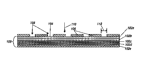
implantable material 100 has a surface 104, as illustrated in FIG. 11A. In one
embodiment, the
0 implantable biocompatible material may comprise one or more layers 102 of
vacuum deposited
material formed into a self-supporting structure, as illustrated by FIG. 11A
showing a first layer
11
CA 02835844 2013-11-12
WO 2012/158614 PCMJS2012/037776
102a, a second layer 102b, a third layer 102c, a fourth layer 102d, and a
fifth layer 102e. In
another embodiment, the implantable biocompatible material includes a bulk
material, either a
bulk material alone or a bulk material covered by the one or more layers 102a-
102e of vacuum
deposited biocompatible material. Five layers 102a-102e of vacuum deposited
material are
illustrated; however, any number of layers may be included as desired or
appropriate.
[049] The one or more layers 102, may have thicknesses that are the same or
different as
desired or appropriate. Each layer may have a thickness in a range from about
1 nanometer to
about 20 micrometers, from about 1 nanometer to about 10 micrometers, from
about 1 nanometer
to about 5 micrometers, or from about 1 nanometer to about 3 micrometers.
Alternating layers
0 102 of varying thicknesses may be applied as to accommodate the geometric
physiologically
functional features.
[050] In this embodiment, the geometric physiologically functional features
may be added to
the surface 104 by adding one or more layers 102 of vacuum deposited material.
For example,
referring to FIGS. 11B-11E, in one process, a mask 106 having holes 108 of
defined size
5 disposed therethrough and patterned throughout coats and is tightly
adhered to at least a first
portion of the surface 104. The holes 108 may be cut through the mask 106, for
example, by
using a laser, wet or dry chemical etching, or other like methods for forming
holes through a
material, or the mask 106 may be fabricated including the holes 108. The
thickness of the holes
108 may range about 1 nanometer to about 20 micrometers, from about 1
nanometer to about 10
0 micrometers, from about 1 nanometer to about 5 micrometers, or from about 1
nanometer to
about 3 micrometers.
[051] The shape of the holes 108 as seen in FIG. 11C or as looking in the
direction of arrow
110 may be any of the shapes described for the geometric physiologically
functional features
including: circle, square, rectangle, triangle, polygonal, hexagonal,
octagonal, elliptical, parallel
,5 lines and intersecting lines, or any combination thereof. The holes 108
may have a width 112, or
diameter 112 if the holes are circular, in a range between about 1 nanometer
and about 75
micrometers, between about 1 nanometer and about 50 micrometers, between about
1 nanometer
and about 2000 nanometers, or between about 1 nanometer and about 200
nanometers. Adjacent
holes 108 may be spaced apart by a distance D in a range from about 1
nanometer to about 20
0 micrometers, from about 1 nanometer to about 10 micrometers, from about 1
nanometer to about
5 micrometers, or from about 1 nanometer to about 3 micrometers. The distance
D may be less
12
than, about equal to or greater than the width 112. In another embodiment (not
shown), the width
112 of each of the holes 108 and/or the distance D between adjacent holes 108
may vary in size
to form a patterned array of the holes 108.
[052] Referring to FIG. 11D, a layer 114 of material was deposited into a
space as defined by
the holes 108 in the mask 106 by vacuum deposition. The layer 114 has a
thickness essentially
the same as that of the mask 106. In some embodiments, the thickness of the
mask may be
variable across the mask 106. After removal of the mask 106, geometric
physiologically
functional features 116 are revealed patterned across the surface 104 of the
implantable material
100. Each of the geometric physiologically functional features 116 includes a
top surface 118.
0 Each of the geometric physiologically functional features 116 has
dimensions as described
hereinabove for the holes 108 in the mask 106.
10531 In another embodiment where geometry of the layer or layers of deposited
material
defines the geometric physiologically functional features, a patterned array
of recesses may be
formed each having a hydrophobic, hydrophilic or surface energy difference
relative to the
5 surface into which the recesses are added, meaning a top most surface of
the deposited layers, the
difference enhancing the binding, proliferation and migration of endothelial
cells to and between
the recesses and across the surfaces, recessed and top most. The hydrophobic,
hydrophilic or
surface energy differences relative to the surface may be formed, by way of
example, any of the
methods disclosed in commonly assigned U.S. Patent Application No. 12/428,981,
filed April,
,0 23,2009.
[054] In this embodiment, the recesses may be formed by a relative lack of
deposition of a layer
or layers onto a surface, or by machining recesses through a layer or layers
of material vacuum
deposited on a surface. For example, to produce a pattern of recesses similar
to the pattern of
geometric physiologically functional features 116 illustrated in FIG. 11E, in
one example, a
,5 process begins by executing the steps described hereinabove with regard
to FIGS. 11A-11E, to
produce the pattern of geometric physiologically functional features 116
illustrated in FIG. 11E,
except in this embodiment, the layer 114 of material is a sacrificial layer of
material that is
removed in a subsequent step.
10551 Referring to FIGS. 12A and 12B, a layer 120 of material is deposited
into spaces
,0 between the geometric physiologically functional features 116 by vacuum
deposition. The layer
120 has a thickness essentially the same as that of the geometric
physiologically functional
13
CA 2835844 2018-11-09
CA 02835844 2013-11-12
WO 2012/158614 PCMJS2012/037776
features 116. In this embodiment, after vacuum deposition of the layer 120,
the geometric
physiologically functional features 116 of the sacrificial layer 114 are
removed, for example, by
chemical etching, photo etching, laser ablation, or other method reveal
geometric physiologically
functional features 122 patterned across the surface 104 of the implantable
material 100. Each of
the geometric physiologically functional features 122 is a recess that has a
thickness or depth
between a surface 124 of the layer 120 and the surface 104.
[056] The shape of the recesses 122 as seen looking in the direction of arrow
126 in FIG. 12B
may be any of the shapes described for the geometric physiologically
functional features
including: circle, square, rectangle, triangle, polygonal, hexagonal,
octagonal, elliptical, parallel
0 lines and intersecting lines, or any combination thereof. The recesses
122 may have the width
112, or diameter if the recesses 122 are circular, in a range between about 1
nanometer and about
75 micrometers, alternatively between about 1 nanometer and about 50
micrometers,
alternatively between about 1 nanometer and about 2000 nanometers, or
alternatively between
about 1 nanometer and about 200 nanometers. Adjacent recesses 122 may be
spaced apart by the
5 distance D in a range from about 1 nanometer to about 20 micrometers,
from about 1 nanometer
to about 10 micrometers, from about 1 nanometer to about 5 micrometers, or
from about 1
nanometer to about 3 micrometers. The distance D may be less than, about equal
to or greater
than the width 112. In another embodiment (not shown), the width 112 of each
of the recesses
122 and/or the distance D between adjacent recesses 122 may vary in size to
form a patterned
0 array of the recesses 122.
[057] In another embodiment, the recesses 122 having width and spacing as
described
hereinabove with regard to FIGS. 12A and 12B may be formed by machining the
recesses 122
through a layer or layers 128 of vacuum deposited material. For example, an
implantable
material 130 having a surface 132, may comprise a bulk material 134, the one
or more layers 128
,5 of vacuum deposited material, or the bulk material 134 and the one or
more layers 128 of
vacuum deposited material, as illustrated in FIG. 13A.
[058] Alternatively, as shown in FIG. 12C, the geometric physiologically
functional features
116 themselves include a plurality of deposited layers, wherein the geometric
physiologically
functional features 116 include the first layer 102a, the second layer 102b,
and the third layer
0 102c. The geometric physiologically functional features 116 are deposited
through a mask as
previously indicated, on top of structural material of the stent or other
medical device include
14
deposited layer 102d and 102e. Alternatively, the geometric physiologically
functional features
116 include the first layer 102a and the second layer 102b, deposited through
the mask whereby
the structural material of the stent or other medical device includes the
layers 102c-102d.
Alternatively, the geometric physiologically functional features 116 include
the first layer 102a,
the second layer 102b, the third layer 102c, and the fourth layer 102d,
whereby the structural
material of the stent or other medical device includes the fifth layer 102e.
When additional layers
102a-102d are included in the geometric physiologically functional feature
116, the thickness of
the layers as deposited can be modified to be a narrower or decreased
thickness as to allow for
the geometric physiologically functional feature 116 to be adjusted to a
particular thickness. The
0 layers of different vacuum deposited materials can be deposited to
create the elevated surfaces
having inherently different material properties. Alternatively, layers of the
same vacuum
deposited material can be deposited having differences in grain size, grain
phase, and/or surface
topography or variations of hydrophobic, hydrophilic or surface energy
difference relative to the
surface of the stent or structural material. The grain size, grain phase,
and/or surface topography
5 or variations of hydrophobic, hydrophilic or surface energy
difference relative to the surface of
the stent or structural material may be formed or included on the surface as
shown in U.S. Patent
Application Serial No. 12/428,981, which was filed April, 23, 2009.
10591 Alternatively, as shown in FIG. 12D, the recesses 122 may include a
plurality of layers
,0 102 to provide for differences in grain size, grain phase, and/or
surface topography or variations
of hydrophobic, hydrophilic or surface energy difference relative to the
surface of the stent or
structural material. The recesses 122 may be formed by the surface 124 being
deposited through
a mask as to form the layer 120 that gives rise to the plurality of recesses
122 with a wall 123. As
such, the recesses 122 include an inner wall 123 including the first layer
102a, the second layer
;5 102b, and the third layer 102c, whereby the surface 104 is on layer
102d, which is exposed on
the bottom of the recess 122 and surface 124 is on top of layer 102a.
Alternatively, the recesses
122 may include a wall of the first layer 102a and the second layer 102b,
whereby the surfaces
124 are deposited through a mask, and the structural material of the stent or
other medical device
includes the layers 102d-102e. Alternatively, the recesses 122 include a wall
of the first layer
0 102a, the second layer 102b, the third layer 102c, and the fourth
layer 102d, and surfaces 124 are
deposited through a mask whereby surface 102e that acts as the surface 104 of
the structural
CA 2835844 2018-11-09
CA 02835844 2013-11-12
WO 2012/158614 PCMJS2012/037776
material of the medical device. When additional layers 102a-102d are included
as the wall in the
geometric physiologically functional feature 116, the thickness of the layers
as deposited can be
modified to be a narrower or decreased thickness as to allow for the geometric
physiologically
functional feature 116 to be adjusted to a particular thickness. The layers of
different vacuum
deposited materials can be deposited to create recesses having inherently
different material
properties. Alternatively, layers of the same vacuum deposited material can be
deposited having
differences in grain size, grain phase, and/or surface topography or
variations of hydrophobic,
hydrophilic or surface energy difference relative to the surface of the stent
or structural material.
[060] Referring to FIG. 13B, recesses 136 may be machined into the surface 132
of the
0 implantable material 130 to have a depth greater than a thickness of a
first layer of material 128a
or recesses 138 may be machined into the surface 132 of the implantable
material 130 to have a
depth greater than a thickness of the first and second layers 128a, 128b of
material. Two layers
arc illustrated for convenience of explanation and illustration; however, any
number of layers
128 of material may be used as desired or appropriate. In this embodiment,
each of the recesses
5 136 has a thickness or depth between the surface 132 of the layer 128a
and a surface 140 that is
within a second layer 128b. Similarly, each of the recesses 138 has a
thickness or depth between
the surface 132 of the layer 128a and a surface 142 that is within the bulk
material 134.
[061] An implantable material including geometric physiologically functional
features
comprising a layer or layers of vacuum deposited material, as illustrated by
the geometric
0 physiologically functional features 116 in FIG. 11E, recesses disposed
through one or more
layers of vacuum deposited material, as illustrated by the recesses 122 in
FIG. 12B or the
recesses 136 or 138 in FIG. 13B, has an inherently different structure than a
block of material
having recesses cut into it. The reason for this inherent difference lies in
the differences in the
materials making up surfaces exposed by the recesses. For example, in the case
of a block of
,5 material and assuming that the block material is uniform in regard to
material properties, an
undisturbed surface of the block and a surface within a recess or groove cut
into the block have
the same material properties.
[062] In contrast, layers of different vacuum deposited materials can be
deposited to create
recessed and/or elevated surfaces having inherently different material
properties. In fact, layers
0 of the same vacuum deposited material can be deposited having differences
in grain size, grain
phase, and/or surface topography. The alternative grain size, grain phase,
and/or surface
16
topography may be included or formed, by way of example, any of the methods
disclosed in
commonly assigned U.S. Patent Application No. 12/428,981, filed April, 23,
2009..
For example, surfaces of the recesses 122, 136 can be deposited to have a
roughened surface topography and a large grain size and surfaces of the
material deposited
defining the recesses 122, 136, for example the layer 120 illustrated in FIG.
12B, can have a
relatively smoother surface topography and/or a smaller grain size.
Alternative grain sizes and
surfaces may be formed and included as shown in U.S. Patent Application Serial
No.
12/428,981, which was filed April, 23, 2009.
0631 It is contemplated that a factor in increasing endothelialization of a
surface of an
0 implanted medical device may be the cleanliness of the surface. In this
context, cleanliness refers
to the presence or lack of contaminant molecules bonding to otherwise
unsaturated chemical
bonds at the surface. A perfectly clean surface, for example as may exist in a
vacuum, comprises
unsaturated bonds at the surface that have not bound to any contaminant
molecules. The
unsaturated bonds provide the surface with a higher surface energy as compared
to a
5 contaminated surface having fewer unsaturated bonds, which have a lower
surface energy.
Measurements of surface energy may be accomplished by contact angle
measurements, as
disclosed in U.S. Patent Application Serial No. 12/428,981, which was filed
April, 23, 2009.
10641 Unfortunately, unsaturated chemical bonds at the surface will bond to
contaminant
molecules when exposed thereto. For example, there are many air-borne
chemistries such as
,0 phthalates, hydrocarbons, and even water that may bond to unsaturated
bonds or otherwise attach
to reactive spots such as, for example, residual negative charges on the
surface of a metal oxide.
Such contaminant molecules, for example, normally occurring hydrocarbons, SO2,
NO, etc.,
occupy otherwise unsaturated bonds thereby reducing the number of unsaturated
bonds and
lowering the surface energy of the surface. Such reduction in the number of
unsaturated bonds
.5 decreases the availability of such unsaturated bonds for interaction
with blood proteins.
[065] The air atmosphere around the surface include normally occurring
impurities which will
be attracted to the unsaturated chemical bonds at levels in the air around
1x10⁹ to 1x10⁶ so it
will take a few seconds before the surface is contaminated by their Brownian
motion, after I
min, most of the unsaturated bond are saturated with contaminants. One
molecular monolayer
0 (i.e. a single layer of molecules) will be adsorbed on the surface. On
longer time scales,
additional molecules may bond to the surface and build multi-layers of
contaminant molecules.
17
CA 2835844 2018-11-09
CA 02835844 2013-11-12
WO 2012/158614 PCMJS2012/037776
The surface of a few molecular monolayers of contaminants may have thickness
of about 0.1-
2nm, which may be detected by sensitive surface analysis as indicated above.
[066] Thus, as relates to endothelialization, a cleaner surface having more
unsaturated bonds
provides increased potential for interaction with blood proteins. It is
contemplated that a
contaminated surface of a vacuum deposited or bulk material can be activated,
or made more
likely to interact with blood proteins, by removing the contaminant molecules
that occupy the
otherwise unsaturated bonds at the surface. There may be several techniques
for accomplishing
such activation, including by way of example and not limitation, chemical
etching, wet chemical
etching, oxidation, electrochemical treatment, thermal treatment, UV-ozone
cleaning, coating by
0 evaporation or sputtering, etc. For example, another technique for
activating a vacuum deposited
surface may be by using plasma electron bombardment under vacuum, a technique
also known
as plasma etching. The contaminant layer may be detected by surface-sensitive
spectrosscopies,
such as Auger electron spectroscopy (AES), x-ray photocmission spectroscopy
(XPS or ESC),
infrared reflection absorption spectroscopy (IRAS, FT-IR, etc.) secondary ion
mass spectroscopy
5 (SIMS), and those disclosed in U.S. Patent Application Serial No.
12/428,981.
[067] Plasma etching the sample to be treated is positioned within a
controlled electrical gas
discharge (a plasma), as schematically shown in FIG. 14. The plasma may be
formed by
applying a high voltage (AC or DC) over a gas under considerably lower
pressure than one
atmosphere (typically 0.1-1mm Hg, or a vacuum). Because of the low pressure
and because gas
0 purity is vital for the process, the discharge and the sample must be
housed in a hermetically
closed system that can be evacuated by vacuum pumps, and whose gas composition
can be
controlled. The plasma also has sufficient energy and momentum to remove atoms
and
molecules that are adsorbed on unsaturated bonds, or are constituents of the
native surface. As
such, the contamination layer bond to unsaturated bonds may be removed, to
recreate the
,5 unsaturated bonds on the surface and thus increasing the surface energy.
Depending on the
parameters of the discharge (gas pressure and composition, applied voltage,
current density,
position of the sample, etc.) the surface treatment can be mild (mainly
removal of the
contamination layer) or more aggressive. The complete surface oxide layer on a
metal may be
removed so that the bare metal is exposed. The latter occurs only provided
that no oxidizing or
0 other reactive gases are present, i.e., the used gas must be a noble gas
such as Ar, Kr, or Xe. By
controlling the gas atmosphere, the composition of the newly formed surface is
controlled; if
18
CA 02835844 2013-11-12
WO 2012/158614 PCMJS2012/037776
oxygen is added, oxide will be formed; if nitrogen or hydrocarbons are added,
surface nitride or
surface carbide, respectively, will form, etc. The gas purity must be high, as
impurities within the
gas will react to the high energy cleaned surfaces.
[068] Because of the omnipresence of contaminant molecules in the environment,
a surface
once activated may not remain activated until implantation into a patient.
Thus, an important
consideration of the activation process is how to preserve the activated
surface long enough to
provide the benefit of activation upon implantation. In this context, the
activated surface may be
preserved by introducing a contaminant gas or liquid into the plasma etching
process in a
controlled manner, which may be easily removed before use of the medical
device. The
0 contaminant layer may be a known biodegradable material or may be a
contaminant layer or
coating of inorganic or organic nature or a mixture of both. For example, the
contaminant layer
may be layer readily removed by a saline or water solution, which are
typically used in flushing
procedures or washing procedures.
[069] Alternatively, the activated surface may be coated with a protective
coating, for example,
5 a biodegradable material that dissolves upon exposure to the in vivo
environment when
implanted. The biodegradable material may alternatively be dissolved via
introduction of an
externally delivered fluid solvent during implantation. Alternatively, the
protective coating may
be a fluid in which the activated device is immersed until implantation. For
example, it is
contemplated that storing the activated surface in water facilitates
preservation of the activation
0 as compared to exposure of the activated surface to air. The
biodegradable material may be any
material, natural or synthetic, that may be broken down by living organisms,
including, but not
limited to a biodegradable organic substance, biodegradable polymer substances
(Poly(lactic
acid) PLA, poly(L-lactic acid) (PLLA), poly(lactic-co-glycolic acid) PLGA,
poly(glycolicacid)
(PGA), Polyethylene glycol, PEG, polytetrafluoroethylene (PTFE), and the
like), peptides or
,5 proteins, carbohydrates, nucleic acids, fatty acids, carbon-containing
compounds, nanoparticles,
microparticles, biocomposites, sol-gel coatings, hydrogels water-soluble
bioactive agent and
poly(alkyl cyanoacrylate) polymer coating; nanoparticle coating formed by
electrospraying; a
poly(diol citrates)-based coatings; natural biodegradable hydrophobic
polysaccharides coatings,
hydrophilic polymers, and the like. Alternatively, other materials may be
used, such as gold,
0 other metals, heparin, silicon carbide, titanium-nitride-oxide,
phoshphorylcholine, and other
medical device coatings.
19
CA 02835844 2013-11-12
WO 2012/158614 PCMJS2012/037776
[070] The method disclosed herein comprehends the creation of a patterned
array of geometric
physiologically functional features elevated relative to a surface of an
implantable biocompatible
material, recessed relative to the surface, or disposed on the surface. For
example, in accordance
with an alternative embodiment, the implantable biocompatible material is
formed of a bulk
material of titanium, nickel-titanium alloy or other titanium-rich alloy
metals or a top most layer
of titanium, nickel-titanium alloy or other titanium-rich alloy metals
deposited over the bulk
material. The titanium, nickel-titanium alloy or other titanium-rich alloy
metal is oxidized to
convert surface titanium to titanium dioxide, then covered with a pattern-mask
and exposed to
high intensity UV irradiation. It is well-known that titanium dioxide (TiO2)
absorbs UV radiation
0 and has been used in a variety of applications as a UV inhibitor to
prevent UV transmission
across a TiO2 barrier layer. It has been discovered that upon exposure to UV
irradiation, an
originally hydrophobic and oleophilic titanium oxide layer becomes
amphiphilic.
[071] The effect of UV irradiation on a titanium oxide surface is believed to
occur because of
unsymmetrical cleavage of the Ti-0 bond to leave Ti 3 ions on the surface in
some regions.
5 Presently, these amphiphilic surfaces are being used in a range of
technological applications,
such as self-cleaning paints and anti-misting glasses. It has been recognized
that these
amphiphilic titanium oxide layers have use in medical applications. Zarbakhsh,
A.,
Characterization of photon-controlled titanium oxide surfaces, ISIS
Experimental Report,
Rutherford Appelton Laboratory, May 16, 2000 (which may be found on the
internet at:
0 WWW. isissLac.uklisis200Preports/11144.pdt).
[072] The amphiphilic state of the UV irradiated titanium oxide may be
advantageously
employed as an alternative to depositing patterned elevated or recessed
geometric
physiologically functional features onto the implantable biocompatible
material. An implantable
biocompatible material fabricated having a bulk substrate or a top most vacuum
deposited layer
,5 of titanium or a titanium alloy is masked with a pattern mask having a
plurality of openings
passing there through. As with the above-described embodiment, the plurality
of openings
preferably have a size and special array selected to define affinity binding
domains and cellular
migration cites for promoting endothelial cell binding and proliferation
across the substrate
surface.
0 [073] The open surface area of each of the plurality of openings in the
pattern mask is
preferably in the range of between about lnm to about 75 pm, and with adjacent
pairs of
CA 02835844 2013-11-12
WO 2012/158614 PCMJS2012/037776
openings being in a spaced apart relationship such that a distance of about mm
to about 75 1,,tm
exists between the openings, the inter-opening being greater than, about equal
to, or less than the
size of the opening. By interposing the pattern mask between a UV source and
the surface of the
implantable biocompatible material, a pattern of UV irradiated regions is
imparted to the surface
implantable biocompatible material, thereby altering the titanium dioxides
present at the
irradiated regions and forming affinity domains at the surface implantable
biocompatible
material.
[074] Referring to FIG. 10A, a portion of an implantable material 56 made of
titanium or a
titanium-alloy is shown having at least one surface 52 and 54 that is oxidized
by heating or an
0 equivalent known by the person skilled in the art. Referring to FIG. 10B,
according to one
embodiment, a machined mask 48 that had laser-cut holes 40 of defined size
from about 1 nm to
about 75 pm, from about 1 nm to about 50 pm, from about 1 nm to about 2000 nm,
and
preferably from about 1 nm to about 200 nm, patterned throughout to coat the
at least one surface
52 of the implantable material 56 and is tightly adhered to the covered
surface 52.
5 [075] Referring to FIG. 10C, the implantable material 56 covered with the
mask 48 is then
illuminated by the ultraviolet rays. Because TiO2 is sensitive to ultraviolet,
the chemical
composition in holes 58 is different from the area that is covered by the
mask. In contrast to the
geometric physiologically functional features illustrated in FIGS. 9C, 11E,
12B, and 13B, the
geometric physiologically functional features 59 in FIG. 10C are not elevated
and therefore have
0 zero thickness relative to the surrounding surface of the implantable
material.
[076] Referring to FIG. 10D, after ultraviolet irradiation, the mask is
removed to reveal the
surface 52 that surrounds the geometric physiologically functional features 59
formed by
ultraviolet irradiation. As described above, because the shape of the holes 58
in the mask 48
could be in any of the shapes described for the geometric physiologically
functional features
,5 including: circle, square, rectangle, triangle, parallel lines and
intersecting lines, and
combinations thereof, the geometric physiologically functional features 58
accordingly adopts
such shapes also.
[077] EXAMPLE 1
[078] Nickel-titanium sheets were heated to oxidize titanium present at the
surface of the sheet.
0 Pattern masks fabricated from machined metal were laser drilled a pattern of
holes having
diameters ranging from 15 [tm to 50 pm, with a single diameter of holes on
each pattern mask. A
21
CA 02835844 2013-11-12
WO 2012/158614 PCMJS2012/037776
single pattern mask was placed over a single nickel-titanium sheet and the
assembly was exposed
to high intensity ultra-violet irradiation. After UV irradiation, the
irradiated nickel-titanium sheet
was placed on a fully endothelialized test surface and maintained at 37 C.
under simulated in
vivo flow conditions and under static flow conditions. Qualitative
observations were periodically
made and it was found that endothelial cells bound to the pattern of UV
irradiated affinity
domains and migrated across the nickel-titanium sheet by proliferating across
the pattern of
affinity domains, eventually fully seeding endothelium on the nickel-titanium
sheet.
[079] EXAMPLE 2
[080] Selected metal pieces (Flat, lx1 cm square pieces (1/16 in. thick) of
electropolished 316L
0 stainless steel, electropolished and heat-treated, electropolished
Nitinol, gold and titanium) were
subjected to radiofrequency plasma glow discharge using an EMS-100 glow
discharge unit
(Electron Microscopy Services, Fort Washington, PA). For this procedure, the
flat metal piece is
placed on a flat metal platform within the glow discharge vacuum chamber. The
plasma
treatments were conducted at a base vacuum pressure of 10-2 mbar in the
presence of a purified
5 argon gas atmosphere. The sample was always at negative potential as the
cathode using an
applied current of 20 mamps for the treatment time of 3 min. Under these
conditions the surface
of the sample is bombarded with argon ions resulting in the removal of surface
oils and other
surface contaminating molecules. Electrostatic force analyses were performed
on these samples
within 2 hr after removal from glow discharge treatment.
0 [081] For calculation of metal surface energy values, contact angle
measurements were
performed using a VCA-2500XE video contact angle system (AST systems,
Billerica, MA) on
the flat metal pieces after cleaning as described above. The surface energy of
all materials
studied was determined by the advancing contact angle measurement of three
standard liquids;
water, formamide and xylene; on each metal surface and calculated by the
harmonic mean
,5 method. Ten videocaptures per second of the advancing fluid
droplet/solid interface were
obtained for water and formamide and 65 captures per second for xylene. All
experiments were
repeated 4 times.
[082] Glow discharge plasma treatment is a method of cleaning and removing
surface
contaminants from metallic as well as other surfaces, schematically shown in
FIG. 15. Glow
0 discharge treatment of many metallic surfaces causes their surfaces to
change from very
hydrophobic surfaces on which water beads to a hydrophilic surface on which
water rapidly
22
CA 02835844 2013-11-12
WO 2012/158614 PCMJS2012/037776
spreads. This can be quantitatively measured using contact angle measurement
techniques,
described above. In the case of stainless steel, a change in water contact
angle was measured
from 98 prior to treatment to 7 after glow discharge. With this profound
alteration in surface
characteristics associated with glow discharge treatment, it was important to
examine whether
these physical alterations in surface behavior might be associated with an
alteration in surface
electrostatic forces. Gold, stainless steel and electropolished Nitinol all
exhibit net attractive
forces subsequent to glow discharge treatment, as shown in FIG. 16. Nitinol
and gold now
exhibit highly attractive forces that are significantly higher (p<.001) than
that observed on
stainless steel.
0 [0831 It is likely based upon the profound change in measured surface
electrostatic energy
associated with glow discharge treatment and a similar dramatic change in
water contact angle
measurements that the two approaches to surface characteristics might be
fundamentally related.
To fully explore this possibility, contact angles on gold, stainless steel,
electropolished Nitinol,
and heat-treated oxidized Nitinol were measured using water, xylene, and
formamide. Using the
5 Harmonic Mean method, these measurements were used to calculate the total
surface energy
associated with each of the metallic surfaces. The final total surface energy
value represents the
sum of the polar and hydrophobic dispersive forces. To evaluate a possible
association with these
components of total surface energy to AFM measured electrostatic forces, the
possible
correlations between electrostatic force and either total surface energy were
examined, the polar
0 component of surface energy or the dispersive component. As demonstrated in
FIG. 17, a
significant correlation was observed between the polar component of total
surface energy and
AFM measured electrostatic force. Within this comparison it is noteworthy that
electropolished
Nitinol exhibits the lowest polar energy component of all four surfaces and,
furthermore, that
when its surface becomes heavily oxidized that the polar component increases
almost 3-fold
,5 (from 1.3 to 3.4 dynes/cm), again, paralleling changes observed in
surface electrostatic force
(FIG. 16).
23