Note: Descriptions are shown in the official language in which they were submitted.
CA 2836274 2017-05-10
1
METHOD AND APPARATUS TO MINIMIZE AIR-SLURRY
SEPARATION DURING GYPSUM SLURRY FLOW
BACKGROUND OF THE INVENTION
The present invention relates to a method and apparatus for preparing
gypsum products (i.e., products comprising calcium sulfate dihydrate) from
starting
materials comprising calcined gypsum (i.e., calcium sulfate hemihydrate or
anhydrite) and water. More particularly, the present invention relates to an
improved
method and apparatus for use in conjunction with the slurry mixer typically
used in
supplying agitated gypsum slurry to a wallboard production line. The present
apparatus provides an improved conduit leading from the mixer which minimizes
air-
slurry separation during gypsum slurry flow through the conduit to the outlet.
It is well known to produce gypsum products by uniformly dispersing
calcined gypsum in water to form a slurry and then casting the slurry into a
desired
shaped mold or onto a surface and allowing the slurry to set to form hardened
gypsum by reaction of the calcined gypsum (calcium sulfate hemihydrite or
anhydrite) with the water to form hydrated gypsum (calcium sulfate dihydrate).
It is
also well known to produce a lightweight gypsum product by uniformly mixing an
aqueous foam into the slurry to produce air bubbles. This will result in a
uniform
distribution of voids in the set gypsum product if the bubbles do not escape
from the
slurry before the hardened gypsum forms. The voids lower the density of the
final
product, which is often referred to as "foamed gypsum."
Prior apparatus and methods for addressing some of the operational problems
associated with the production of foamed gypsum are disclosed in commonly-
assigned U.S. Pat. Nos. 5,683,635, 5,643,510, 6,494,609 and 6,874,930. The
present
invention relates generally to the use of foamed gypsum in the production of
gypsum
wallboard.
A gypsum wallboard mixer typically includes a housing defining a mixing
chamber with inlets for receiving calcined gypsum and water, among other
additives
well known in the art. The mixer includes an impeller or other type of
agitator for
agitating the contents to be mixed into a mixture or slurry. Such mixers
typically
have a rectangular discharge gate or slot with a cutoff block or door. The
discharge
gate controls the flow of slurry from the mixer, and is difficult to adjust to
change
CA 02836274 2013-11-14
WO 2012/166357 PCT/US2012/038037
2
slurry flow when product requirements change, such as when thicker or thinner
wallboard is desired.
It has been found that it is desirable to reduce the pressure of the slurry in
the
slurry conduit before the slurry leaves the conduit outlet in order to avoid
disrupting
the distribution of the previously deposited slurry in a wallboard production
line.
This is accomplished by providing one or more changes of direction of the
conduit
between the mixer and the conduit outlet, such as by providing one or more
elbows or
bends along the length of the conduit and also by enlarging a cross section of
the flow
stream of slurry in the conduit while at the same time changing the direction
of the
flow stream. In the known constructions, the enlargement of the flow stream
and the
changing of the direction of the flow stream take place simultaneously in a
boot which
comprises a 90 degree elbow that has an increasing diameter throughout the 90
degree
bend of the elbow.
When the slurry-foam additive mixture is such that the air content approaches
or exceeds 40%, then as the flow stream of the mixture passes through the
elbow with
the enlarging diameter, there is a significant and undesirable separation of
the air from
the slurry.
Therefore, it would be an improvement in the art if there were a method and
an apparatus that still provided for reducing the pressure of the slurry flow
stream via
changes of direction of the conduit and increases in the diameter of the flow
stream,
while reducing the amount of separation of the air from the slurry in the
conduit.
SUMMARY OF THE INVENTION
What the inventors have surprisingly discovered is that changing the direction
of flow of the flow stream at the same time as enlarging the cross section of
the flow
stream causes a greater separation of the air from the slurry than if the
changing of the
direction of the flow stream and enlarging a cross section of the flow stream
take
place at different times and at different spatial locations.
Accordingly, an unexpected improvement is provided by the present apparatus
and method in which a conduit is used to discharge the slurry from the mixer
in which
the changing of the direction of the flow stream in the conduit and an
enlargement of
the cross section of the flow stream are both provided, yet at different times
and
spatial locations.
CA 2836274 2017-05-10
3
In an embodiment, a method for providing an evenly mixed additive enhanced
gypsum slurry to a web includes inserting calcined gypsum and water into a
mixing
chamber of a mixer through at least one inlet of the mixing chamber, agitating
the
contents of the mixing chamber to form a slurry comprising an aqueous
dispersion of
the calcined gypsum, passing the slurry from an outlet of the mixer into a
slurry
dispensing apparatus including a conduit, introducing an additive into the
slurry at a
point along a length of the conduit in the slurry dispensing apparatus to
achieve a flow
stream of a slurry/additive mixture through the conduit, and expanding a cross
section
of the flow stream in the conduit while not changing a direction of the flow
stream
and changing a direction of the flow stream while not expanding the cross
section of
the flow stream and conduit prior to the flow steam exiting from an outlet of
the
conduit.
In still another embodiment, an apparatus is configured for connection to a
mixer for receiving a gypsum slurry, which includes a conduit having a main
inlet in
slurry receiving communication with the mixer outlet and extending in a
downstream
direction to a spout for discharging the slurry, the conduit providing a flow
path for a
flow stream of the slurry, at least one bend in the conduit to cause a change
of
direction of the flow stream between the main inlet and the spout, wherein a
cross
section of the flow stream does not expand in the bend, and at least one
expansion
section in the conduit to cause an expansion of a cross section of the flow
stream
between the main inlet and the spout, wherein the flow stream does not change
direction in the at least one expansion section.
In a broad aspect, moreover, the present invention provides a method of
providing an evenly mixed additive enhanced gypsum slurry to a web,
comprising:
inserting calcined gypsum and water into a mixing chamber of a mixer through
at
least one inlet of the mixing chamber; agitating the contents of the mixing
chamber to
form a slurry comprising an aqueous dispersion of the calcined gypsum; passing
the
slurry from an outlet of the mixer into a slurry dispensing apparatus
including a
conduit; introducing an additive into the slurry at a point along a length of
the conduit
in the slurry dispensing apparatus to achieve a flow stream of a
slurry/additive mixture
through the conduit; changing a direction of the flow stream while not
changing a
cross section of the flow stream, and thereafter, directing the flow stream
through a
linear leg of the conduit without changing a cross section of the flow stream
or a
CA 2836274 2017-05-10
3a
direction of the flow stream, and thereafter, changing a direction of the flow
stream
while not changing a cross section of the flow stream, and thereafter
expanding a
cross section of the flow stream in the conduit while not changing a direction
of the
flow stream, all prior to the flow steam exiting from an outlet of the
conduit.
In another broad aspect, the present invention provides an apparatus
configured for connection to a mixer for receiving a gypsum slurry, said
apparatus
comprising: a conduit having a main inlet in slurry receiving communication
with the
mixer outlet and extending in a downstream direction to a spout for
discharging the
slurry, said conduit providing a flow path for a flow stream of the slurry;
two spaced
apart bends in said conduit to cause a change of direction of said flow stream
between
said main inlet and said spout, wherein a cross section of the flow stream
does not
expand in the bends; a linear section of said conduit extending between the
two bends,
wherein the cross section of the flow stream does not expand in the linear
section, and
at least one expansion section in said conduit to cause an expansion of a
cross section
of said flow stream between downstream one of the two bends and said spout,
wherein
the flow stream does not change direction in the at least one expansion
section.
In another broad aspect, the present invention provides a method of providing
an evenly mixed additive enhanced gypsum slurry to a web, comprising:
inserting
calcined gypsum and water into a mixing chamber of a mixer through at least
one inlet
of the mixing chamber; agitating the contents of the mixing chamber to form a
slurry
comprising an aqueous dispersion of the calcined gypsum; passing the slurry
from an
outlet of the mixer into a slurry dispensing apparatus including a conduit;
introducing
an additive into the slurry at a point along a length of the conduit in the
slurry
dispensing apparatus to achieve a flow stream of a slurry/additive mixture
through the
conduit; and changing a direction of the flow stream while not changing a
cross
section of the flow stream, and thereafter, directing the flow stream through
a linear
leg of the conduit without changing a cross section of the flow stream or a
direction of
the flow stream, and thereafter, expanding a cross section of the flow stream
without
changing a direction of the flow stream, and thereafter changing a direction
of the
flow stream while not changing a cross section of the flow stream, all prior
to the flow
steam exiting from an outlet of the conduit.
In another broad aspect, the present invention provides an apparatus
configured for connection to a mixer for receiving a gypsum slurry, said
apparatus
CA 2836274 2017-05-10
3b
comprising: a conduit having a main inlet in slurry receiving communication
with the
mixer outlet and extending in a downstream direction to a spout for
discharging the
slurry, said conduit providing a flow path for a flow stream of the slurry; a
first bend
in said conduit to cause a change of direction of said flow stream between
said main
inlet and said spout, wherein a cross section of the flow stream does not
expand in the
bend: a linear segment in said conduit between said first bend and said spout,
wherein
a cross section of the flow stream does not expand in the linear segment; at
least one
expansion section in said conduit to cause an expansion of a cross section of
said flow
stream between said linear segment and said spout, wherein the flow stream
does not
change direction in the at least one expansion section; and a second bend in
said
conduit to cause a change of direction of said flow stream between said
expansion
section and said spout, wherein a cross section of the flow stream does not
expand in
the bend.
BRIEF DESCRIPTION OF THE DRAWINGS
The features of the present invention which are believed to be novel, are set
forth with particularity in the appended claims. The invention, together with
further
objects and advantages, may best be understood by reference to the following
description taken in conjunction with the accompanying drawings, in the
several
Figures in which like reference numerals identify like elements, and in which:
Figure 1 is a fragmentary schematic overhead plan view of a mixing apparatus
incorporating the features of the invention.
Figure 2 is a side elevational view of a first embodiment of the pressure
reducing apparatus of FIG. 1 shown in isolation.
CA 02836274 2013-11-14
WO 2012/166357 PCT/US2012/038037
4
Figure 3 is a side elevational view of a second embodiment of the pressure
reducing apparatus of FIG. 1 shown in isolation.
Figure 4 is a fragmentary schematic overhead plan view of an alternate
embodiment of the mixing apparatus of FIG. 1.
DETAILED DESCRIPTION OF THE PREFERRED EMBODIMENTS
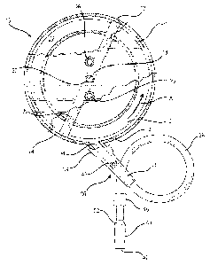
Referring now to FIG. 1, a mixing apparatus for mixing and dispensing a
slurry is generally designated 10 and includes a mixer 12 having a housing 14
configured for receiving and mixing the slurry. The housing 14 defines a
mixing
chamber 16 which is preferably generally cylindrical in shape, has a generally
vertical
axis 18, and upper radial wall 20, a lower radial wall 22 and an annular
peripheral
wall 24. An inlet 26 for calcined gypsum and an inlet 28 for water are both
positioned
in the upper radial wall 20 proximate the vertical axis 18. It should be
appreciated
that the inlets 26, 28 are connected to gypsum and water supply containers
respectively (not shown), such that gypsum and water can be supplied to the
mixing
chamber 16 by simple gravity feed. Also, as is well known in the art, other
materials
or additives in addition to gypsum and water, often employed in slurries to
prepare
gypsum products (e.g. accelerators, retarders, fillers, starch, binders,
strengtheners,
etc.) can also be supplied through these or other inlets similarly positioned.
An agitator 30 is disposed in the mixing chamber 16 and has a generally
vertical drive shaft 32 positioned concentrically with the vertical axis 18
and extends
through the upper radial wall 20. The shaft 32 is connected to a conventional
drive
source such as a motor for rotating the shaft at whatever speed is appropriate
for
agitating the agitator 30 to mix the contents of the mixing chamber 16. Speeds
in the
range of 275-300 rpm are common. This rotation directs the resulting aqueous
slurry
in a generally centrifugal direction, such as in a counter-clockwise outward
spiral
indicated by the arrow A. It should be appreciated that this depiction of an
agitator is
relatively simplistic and meant only to indicate the basic principles of
agitators
commonly employed in gypsum slurry mixing chambers known in the art.
Alternative agitator designs, including those employing pins or paddles, arc
contemplated.
An outlet 34, also referred to as a mixer outlet, a discharge gate or a slot,
is
provided in the peripheral wall 24 for the discharge of a portion comprising
more than
CA 02836274 2013-11-14
WO 2012/166357 PCT/US2012/038037
half of the well-mixed slurry into what is generally referred to herein as a
mixing and
dispensing apparatus 36. While conventional outlets are typically rectangular
in
cross-section, the present outlet 34 is preferably circular in cross-section,
however
other shapes are contemplated depending on the application. Also, while it is
5 contemplated that the specific configuration of the mixer 12 may vary, it
is preferred
that the present mixer is of the centrifugal type commonly used in the
manufacture of
gypsum wallboard, and also of the type in which the outlet 34 dispenses the
slurry
tangentially to the housing 14. While conventional mixers typically provide a
cutoff
block at the outlet 34 to mechanically adjust the flow of slurry for the
desired
thickness of wallboard, typically ranging from 1/4" to 1", it has been found
that such
a block often provides a site for the premature setting of gypsum, resulting
in slurry
buildup and eventual clogging and disruption of the production line.
The mixing and dispensing apparatus 36 includes an elongated, preferably
cylindrical tube or conduit 38 and having a main inlet 39 in slurry receiving
communication with the mixer outlet 34, and has an additive inlet 40 such as a
nipple
for the introduction of aqueous foam or other desired additive, such as
retarders,
accelerators, dispersants, starch, binders, and strength-enhancing products
such as
poly-phosphates, typically sodium trimetaphosphate, all of which are known in
the
wallboard art, after the slurry has been substantially mixed. It is desired
that when
foam is the additive, it is uniformly mixed in the slurry but not excessively
agitated to
the extent that it is broken down. As such, it is common to introduce the foam
into
the additive inlet 40 just after or downstream of, yet close to the outlet 34
and the
main inlet 39 to prolong mixing time with the slurry. However, depending on
the
particular application, it is contemplated that the additive such as foam may
be
introduced at other places along the apparatus 36.
It is preferred that the length of the mixing and dispensing apparatus 36 be
in
the range of at least 48 inches (120 cm), however it is contemplated that the
length
may vary depending on the particular application and the constraints of the
particular
gypsum wallboard production line. The extended length of the mixing and
dispensing
apparatus 36 is desirable for providing time for the foam to mix uniformly
with the
slurry after the point of additive introduction, and prior to dispensing the
slurry upon a
wallboard forming area such as the web of wallboard paper or upon a previously
dispensed layer of relatively denser gypsum slurry, also deposited upon a web
of
CA 02836274 2013-11-14
WO 2012/166357 PCT/US2012/038037
6
wallboard paper. Since the preferred application for the present invention is
a gypsum
wallboard production line, the gypsum slurry with additives is commonly
dispensed
or discharged upon such a web.
A feature of the present mixing apparatus 10 is that the conduit 38 is placed
in
fluid communication with the outlet 34 upstream from the introduction of foam
at the
inlet 40, and includes a discharge spout 42 for dispensing the slurry upon the
web as
described above. The conduit 38 is preferably a flexible hose of rubber or
rubber-like
material (although rigid conduits are contemplated) and is of sufficient
length to
provide extra time for the foam or other additive to become more uniformly
mixed
within the slurry. While rigid conduits are also contemplated, best results
have been
obtained using hoses which are double reinforced to avoid kinking, preferably
having
a smooth inner surface, and being dimensioned in the range of 11/2 -3 inches
(3.75-7.5
cm) inner diameter. Other diameters are contemplated to suit the application.
In the
present invention, a preferably relatively rigid additive inlet portion 44
bearing the
inlet nipple 40 is in the approximate range of 6-24 inches (15-60 cm), and
with the
preferably flexible hose piece conduit, has a total length at least in the
approximate
range of 50 to 168 inches (125-420 cm), while longer lengths are contemplated,
such
as when increased slurry residence time is desired for more complete mixing.
It is
contemplated that in some applications, the additive inlet portion 44 is also
made of
flexible, rubber-like material and is in the shape of a hose. When the
additive inlet
portion 44 and the conduit 38 are made of dissimilar materials, they are
joined to each
other with adhesives, clamps, ultrasonic welding or other known fastening
technologies in a way which will provide a smooth transition and which
minimizes
internal obstructions which might provide a site for the collection and
premature
setting of slurry.
A drawback of conventional gypsum slurry mixing apparatuses is that a
canister is often used downstream of the discharge gate to reduce the slurry
pressure.
Another goal of the present invention is to eliminate the canister and its
inherent
problems. Accordingly, the present mixing and dispensing apparatus 36 is
configured
to maintain a generally smooth flow of the slurry from the main inlet 39 to
the
discharge spout 42 without a flow disrupter in the nature of the prior
canisters.
Sufficient mixing action of the additive with the slurry occurs without the
need for
any additional energy or force being applied to the slurry or additive in the
conduit 38
CA 02836274 2013-11-14
WO 2012/166357 PCT/US2012/038037
7
through which they pass. This is in contrast to an undeterministic nature of
the flow
through the prior canisters, in which uneven mixing of additives and slurry
often
occurred.
The flexibility of the present mixing and dispensing apparatus 36, and
specifically the conduit 38 permits coiled or serpentine configurations that
extend the
length of the mixing chamber 16, and thus increase the residence time in which
the
foam and/or other additive can complete its mixing with the slurry without
requiring a
longer production line. Unlike conventional wallboard mixing apparatuses, in
the
present invention the conduit 38 of the mixing and dispensing apparatus 36 is
directly
connected to the gate portion 44, and ultimately to the outlet 34 without
intervening
devices such as a canister. Also, the preferably flexible construction of at
least a
portion of the conduit 38 reduces the tendency for gypsum to prematurely set
up in
the interior and cause undesirable clogging.
Another feature provided in some embodiments of the present mixing
apparatus 10 is at least one conduit restrictor or flow restrictor 46
associated with the
mixing and dispensing apparatus 36 for creating back pressure in the gate and
ultimately in the mixing chamber 16, for controlling the flow of slurry from
the spout
42 and for at least reducing and generally preventing the buildup of slurry in
the gate
and the mixer. In the preferred embodiment, the restrictor 46 is of the type
which;
exerts an even, circular or concentric clamping force on the flexible conduit
38. Also,
the preferred restrictor 46 exerts its clamping force on the exterior of the
conduit 38,
so that an internal passageway of the conduit is not obstructed by valve
components.
The preferred restrictor 46 is a dynamically adjustable valve, i.e., is
adjustable
while the mixer 12 is in operation and slurry is being emitted from the spout
42, and is
taken from the group consisting of pinch valves, muscle valves, concentric
valves,
iris-action valves and butterfly valves. In some low-pressure applications,
simple
hose clamps are also suitable. It is contemplated to use a transition between
a larger
diameter hose to a smaller diameter hose section as the restrictor 46 for
reducing the
volume of dispensed slurry, and for creating backpressure. For best results,
the valve
46 is located on the conduit 38 near the spout 42 to provide the most
efficient use of
the length of the conduit for complete mixing of the foam into the slurry,
however
other locations farther from the spout are contemplated depending on the
application.
CA 02836274 2013-11-14
WO 2012/166357
PCT/US2012/038037
8
Referring now to FIGS. 1-3, a further feature of the present mixing apparatus
is a pressure reducing apparatus or pressure reducer, shown generally at 50,
in the
mixing and dispensing apparatus 36 for reducing the pressure or force of the
slurry
being dispensed from the spout 42. A typical mixer 12 of the type used with
the
5 present invention generates a slurry velocity in the approximate range of
700-2200
ft/min, measured at the discharge gate or outlet 34 with a correspondingly
high force
or pressure. Unless this force or pressure is reduced significantly, the force
of the
output from the spout 42 will disrupt the distribution of the previously
deposited
slurry, causing the above-described "washout," and will result in uneven
wallboard.
10 Thus, the pressure reducer 50 is needed so that the discharge from the
spout 42 is
acceptably slow and even.
In the preferred embodiment, the pressure reducer 50 is disposed in close
association with the spout 42 and generally defines at least one and perhaps
two or
more bends 52, 54 in the conduit 38. The bends may each be in the range of 30
to 90
degrees and the radius of the bends may be relatively tight, such as not
greater than a
diameter of the conduit. The objective of the bends 52, 54 is to cause the
flow of
slurry in the conduit 38 to undergo at least one and perhaps at least two
deflections
(which may be approximately right angle deflections) prior to exiting the
spout 42. It
has been determined that it is important that the diameter of the conduit at
the bends
be constant, and not expanding. Each successive deflection will further reduce
the
output pressure of the slurry measured at the spout 42. It has also been found
that
positioning the conduit 38 to have an upwardly extending portion causes
gravitational
forces to reduce the pressure of the slurry.
As seen in FIGs. 2 and 3, the pressure reducer 50 also includes an expanding
portion 60 in which a cross sectional area of the flow stream of the slurry
increases as
the flow stream passes through this expanding portion. In this portion of the
pressure
reducer, it is important that the direction of flow of the flow stream not
change, or at
least that it not change significantly or abruptly.
FIG. 2 shows a first embodiment of the pressure reducer 50 in isolation where
the bend 54 precedes the expanding portion 60 in the flow direction. In this
embodiment, the bend 54 is located upstream of the expanding portion 60. FIG.
3
shows a second embodiment of the pressure reducer 50 in isolation and shows
the
CA 02836274 2013-11-14
WO 2012/166357
PCT/US2012/038037
9
expanding portion 60 preceding the bend 54 in the flow direction. That is, the
expanding portion 60 is located upstream of the bend 54.
Referring now to FIG. 4 an alternate embodiment of the mixing apparatus 10
is designated 100. Components of the apparatus 100 which are shared with the
apparatus 10 are designated with the same reference numbers. The main
distinguishing feature of the apparatus 100 is that the additive inlet is
moved from its
former location 40 near the mixer outlet 34 and is preferably provided in the
form of a
foam injection block 64. The block 64 is located downstream of the valve 46,
or
between the valve and the spout 42. The purpose of this placement is to
address the
potential, in some applications, for the foam additive to be used in excessive
amounts,
or to prematurely break down upon the application of backpressure by the
conduit
restrictor 46.
By introducing the foam after the backpressure has been created by the
conduit restrictor 46, the destructive forces acting on the foam will be
reduced.
However, to promote even distribution of the foam or other additive in the
slurry
between the restrictor 46 and the spout 42, there must be sufficient length
provided to
the conduit 38 in this region to provide adequate blending time, otherwise
known as a
slurry travel distance, which is sufficient to promote satisfactory foam or
other
additive blending in the slurry. The length of the conduit 38 in this region
will vary
with the application.
In operation, it will be seen that a system for providing an evenly mixed
slurry
to a web is provided, including inserting calcined gypsum and water into the
mixing
chamber 16 through one or more inlets 26, 28 of the mixing chamber, agitating
the
contents of the mixing chamber to form an aqueous dispersion of the calcined
gypsum, emitting the agitated contents from the outlet 34 of the mixer 12,
passing the
agitated contents into the main inlet 39 of the mixing and dispensing
apparatus 36,
36a-e, introducing an aqueous foam into the mixture at the gate, preferably
through
the inlet nipple 40, creating a back pressure on the mixture in the gate by
constricting
the area of mixture being emitted from the flexible conduit 38, 38a-e of the
gate, the
back pressure being created by constricting the conduit 38, such as with the
valve 46,
and controlling the pressure of slurry and additive dispensed from the spout
42, 42c,
42e such as by the pressure reducer 50 in its various configurations. In the
preferred
embodiment, the slurry pressure is reduced by being forced to change direction
CA 02836274 2013-11-14
WO 2012/166357
PCT/US2012/038037
approximately 90 degrees at least once and perhaps twice or more. The cross
sectional area of the slurry flow stream is also enlarged as the flow stream
moves
through the conduit, however, the change of direction of the flow stream and
the
expansion of the cross section of the flow stream should occur at different
times and
5 spatial locations along the conduit.
Where possible, the flexible conduit 38 extends generally directly down the
board line. It is contemplated that the conduit 38 may extend linearly at
least as much
as 60 inches (150 cm) past the mixer 12. The benefits of improved foam/slurry
mixing achieved by the present invention include: reduction and/or elimination
of
10 blisters in the board; uniformity of the board, leading to improved
strength; and
potential water reduction from the board formulation, which in turn will led
to energy
savings in the kiln or an increase in line speed.
While specific embodiments of the slurry conduit of the present invention
have been shown and described, it will be appreciated by those skilled in the
art that
changes and modifications may be made thereto without departing from the
invention
in its broader aspects and as set forth in the following claims.