Note: Descriptions are shown in the official language in which they were submitted.
CA 02836366 2013-11-15
PCT/EP2012/058606 / 2010P26109W0
1
Description
Converter arrangement
The invention relates to a converter arrangement having at least one
AC voltage connection, at which an alternating current can be fed in
or drawn, and at least one DC voltage connection, at which a direct
current can be fed in or drawn.
A converter arrangement of this type is known from the publication "An
Innovative Modular Multilevel Converter Topology Suitable for Wide
Power Range" (A. Lesnicar and R. Marquardt, 2003 IEEE Bologna Power
Tech Conference, 23-26 June 2003, Bologna, Italy). This previously
known converter arrangement is a so-called Marquardt converter
arrangement, which includes at least two series circuits which are
connected in parallel, the outer terminals of which form DC voltage
connections of the converter arrangement. Each of the series circuits
connected in parallel includes in each instance at least two
submodules connected in series, each of which includes at least two
switches and a capacitor. The voltage level at the DC voltage
connections can be set by suitable activation of the switches.
The object underlying the invention is to specify a converter
arrangement, which can be used especially universally.
This object is achieved according to the invention by a converter
arrangement having the features according to claim 1. Advantageous
embodiments of the inventive converter arrangement are specified in
the subclaims.
Provision is made in accordance with the invention for an energy
storage device to be connected to the capacitor of at least one of the
submodules, wherein a filter is connected electrically between the
capacitor and the energy storage device.
CA 02836366 2013-11-15
,
,
PCT/EP2012/058606 / 2010P26109W0
2
One significant advantage of the inventive converter arrangement
consists in this, contrary to previously known converter arrangements,
having one or a number of additional connections, at which energy can
be stored and/or buffered. This a],lows :the converter arrangement to be
used in technical systems in a particularly versatile fashion. For
instance, the inventive converter arrangement can be used to
distribute electrical energy, in other words as a type of energy
distribution system or as a component of a complex energy distribution
system, wherein energy buffering is enabled. The submodules of the
inventive converter arrangement can be distributed spatially, for
instance across an entire urban area and form local draw or feed-in
points of the energy distribution system in order to draw and/or feed
in electrical energy. The filter provided in accordance with the
invention between the energy storage device and the capacitor (module
capacitor) advantageously allows the energy storage device to be
effectively protected from voltage fluctuations at the capacitor,
which are produced indirectly or directly by the alternating voltage
present at the AC voltage connection of the converter arrangement, as
a result of which the service life of the energy storage device can be
significantly increased.
The filter is preferably embodied such that it attenuates at least the
fundamental frequency of the alternating voltage present at the AC
voltage connection. Alternatively or in addition, the filter can
attenuate at least the first and/or second harmonic of the alternating
voltage present at the AC voltage connection.
The filter is preferably a low-pass filter or a band-pass filter, the
limit frequency and/or upper limit frequency of which is lower than
the fundamental frequency of the alternating voltage present at the AC
voltage connection. With such an embodiment, the energy storage device
is protected both from the fundamental frequency and the harmonics of
the alternating voltage present at the AC voltage connection and also
CA 02836366 2013-11-15
PCT/EP2012/058606 / 2010P26109W0
3
from the switching frequency of the control voltages present at the
switches of the respective switching module. The switching frequency
of the control voltages present at the switches of the respective
switching module may lie in the kilohertz range for instance.
4
With efficient filtering in mind, it is considered to be advantageous
if the limit frequency of the low-pass filter and/or the upper limit
frequency of the band-pass filter is maximally as large as half of the
fundamental frequency of the alternating voltage present at the AC
voltage connection.
The filter may be an active or a passive filter. A passive filter may
include for instance a simple throttle or a parallel oscillating
circuit (anti-resonant circuit) with a corresponding bandwidth. An
active filter may be embodied for instance as a PFC filter (efficiency
factor correction filter) with active components. A number of these or
comparable filter units or a combination of various filter topologies
are possibly advantageous.
The energy storage capacity of the energy storage device is preferably
at least 100 times the energy storage capacity of the capacitor, in
order to allow for energy storage which extends clearly beyond the
energy storage of the capacitor.
The energy storage device is preferably an electrochemical energy
storage device, in particular a rechargeable battery.
In respect of the AC voltage connections of the converter arrangement,
it is considered to be advantageous if each of the series circuits in
parallel has an intermediate connection in each instance, which, in
terms of potential, lies between two submodules of the respective
series circuit, and each intermediate connection forms one of the AC
voltage connections respectively.
CA 02836366 2013-11-15
PCT/EP2012/058606 / 2010P26109W0
4
The converter arrangement preferably operates in a multi-phase manner,
e.g. in three-phase, and includes at least one series circuit with at
least two submodules which are connected in series respectively per
phase.
The invention relates furthermore to an energy distribution system for
supplying a supply area with electrical energy, wherein the energy
distribution system comprises at least one connection for feeding in
electrical energy and a plurality of connections for drawing the fed-
in electrical energy.
In respect of such an energy distribution system, it is considered to
be advantageous if the energy distribution system comprises a
converter arrangement (as is described above), wherein the at least
one connection of the energy distribution system is formed to feed in
the electrical energy through a connection of the converter
arrangement and at least one subset of the connections of the energy
distribution system is formed to draw the fed-in electrical energy
through connections of the submodules of the converter arrangement and
wherein at least one subset of the connections of the submodules of
the converter arrangement is used to store or buffer energy.
With regard to the advantages of the inventive energy distribution
system, reference is made to the afore-cited advantages of the
inventive converter arrangement, since the advantages of the inventive
converter arrangement essentially correspond to those of the inventive
energy distribution system.
It is considered to be advantageous if the submodules are locally
distributed by way of the supply area to be supplied with electrical
energy by the energy distribution system. This allows relatively large
supply areas, for instance entire urban areas, to be supplied with
electrical energy with the aid of the submodules.
CA 02836366 2013-11-15
PCT/EP2012/058606 / 2010P26109W0
A wind farm with a plurality of wind generators and a converter
arrangement, as described above, is also considered to be inventive.
The wind generators are preferably connected in each instance to a
submodule of the converter arrangement.
A method for operating a converter arrangement, as described above, is
also considered to be inventive. In accordance with the invention,
electrical energy is drawn from the submodule at a connection of at
least one of the submodules and is buffered or buffered electrical
energy is fed into the submodule.
The energy storage devices are preferably lithium-ion batteries,
lithium iron phosphate batteries, lithium polymer batteries, Pb
batteries, NiCd batteries, NiMH batteries, high temperature batteries,
NaS batteries, ZEBRA batteries, sodium-air batteries, storage
capacitors, double layer capacitors and/or hybrid capacitors.
The energy storage device can contain batteries in the form of battery
packs, which each comprise individual cells which are connected in
series or in parallel. In the case of cells connected in series, it is
considered to be advantageous if battery management is integrated into
the battery packs, said battery management allowing for safe operation
of the battery pack in a predetermined temperature and voltage window.
If predetermined turn-off conditions are achieved in such a case
(energy storage device is fully charged or discharged, or a maximum or
minimum voltage of the battery pack is reached), additional energy can
be exchanged between the energy storage device and converter
arrangement by way of a corresponding activation of the switches of
the submodules of the converter arrangement. To this end, the
converter arrangement need only be operated as a conventional
Marquardt module.
Furthermore, it is considered to be advantageous if the energy storage
device or devices is/are each equipped with monitoring electronics
CA 02836366 2013-11-15
PCT/EP2012/058606 / 2010P26109W0
6
which communicate with a superordinate unit. The superordinate unit
can in such cases control the charging and/or discharging of the
energy storage device depending on the energy situation of the
converter arrangement.
The energy storage devices are preferably controlled using an
individual control algorithm, in order to optimize the storage
process. Furthermore, it is also considered to be advantageous if the
energy storage devices are equipped with a preferably independently
operating symmetry circuit.
The invention is subsequently explained in more detail with the aid of
exemplary embodiments, in which, by way of example
Figure 1 shows an exemplary embodiment of an inventive converter
arrangement and
Figure 2 shows an exemplary embodiment of an inventive energy
distribution system, which is equipped with an inventive converter
arrangement.
For the sake of clarity, the same reference characters are always used
in the figures for identical or comparable components.
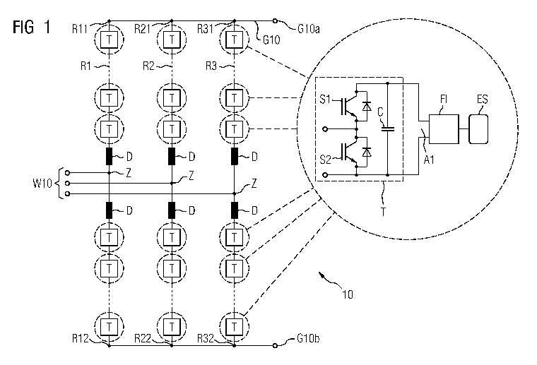
An exemplary embodiment of a three-phase converter arrangement 10 is
shown in Figure 1. This includes AC voltage connections W10 for
feeding in alternating current. Furthermore, it is equipped with a DC
voltage side G10, which includes two DC voltage connections GlOa and
GlOb.
The converter arrangement 10 comprises three series circuits R1, R2
and R3 which are connected in parallel, the outer connections R11, R21
and R31 of which are connected to the DC voltage connection GlOa. The
outer connections R12, R22 and R32 are connected to the DC voltage
CA 02836366 2013-11-15
PCT/EP2012/058606 / 2010P26109W0
7
connection GlOb on the DC voltage side G10. In other words, the outer
connections of the three series circuits R1, R2 and R3 form the DC
voltage side G10 of the converter arrangement 10.
Each of the three series circuits i, R? and R3 is equipped in each
instance with six series-connected submodules T and two inductors D.
An intermediate connection Z is disposed between the two inductors D,
said intermediate connection Z, in terms of potential, lying between
the upper three submodules in Figure 1 and the lower three submodules
in Figure 1 and forming one of the three AC voltage connections W10 of
the converter arrangement 10.
By way of example, the structure of the submodules T can be seen in
Figure 1. In the exemplary embodiment according to Figure 1, each of
the submodules T comprises two switches Si and S2 and a capacitor C
respectively. The connection contacts of the capacitor C of the
submodule T form a connection Al of the submodule, at which electrical
energy can be drawn from the submodule T or fed into the submodule.
Direct current can be fed in or drawn at the connection Al.
A filter Fl and an energy storage device ES can be connected to the
capacitor C and/or to the connection Al of one or a number of the
submodules T, as indicated in the dashed circle in Figure 1. The
energy storage device ES is used to store and/or buffer energy, which,
in the case of corresponding activation of the switches S1 and S2, is
drawn from the converter arrangement 10 by way of the respective
submodule T. The energy stored in the energy storage device can also
be fed back into the converter arrangement 10 at any time by way of
the respective submodule T, by the switches Si and S2 being activated
accordingly.
In order to activate the switches S1 and S2, a module-individual or a
central control facility is preferably provided, which is not shown in
Figure 1 for reasons of clarity. If electrical energy is to be stored
CA 02836366 2013-11-15
PCT/EP2012/058606 / 2010P26109W0
8
in the energy storage device ES, the switches 51 and S2 are activated
accordingly such that energy flows in the direction of the switches 51
and S2. If electrical energy is to be drawn from the energy storage
device ES, the switches 51 and S2 are activated accordingly such that
energy flows in the direction of tile energy storage device ES.
The filter Fl is preferably embodied such that it attenuates at least
the fundamental frequency of the alternating voltage present at the AC
voltage connection, as well as its first and second harmonic. The
filter Fl thus protects the assigned energy storage device from a
periodic charging and discharging with the frequency (or a multiple
thereof) of the alternating voltage present at the AC voltage
connection W10.
In summary, it allows the converter arrangement 10, on account of the
embodiment of the submodules T, to draw or feed in electrical energy
at the connection Al of each submodule T. The converter arrangement 10
can thus be used as an energy distribution system. If a filter Fl and
an energy storage device ES are connected to the connection Al, energy
storage can further take place, in particular energy buffering.
An exemplary embodiment of an energy distribution system 10 is shown
by way of example in Figure 2, said energy distribution system being
formed by a converter arrangement 10, as was explained in conjunction
with Figure 1.
The energy distribution system 100 comprises a connection E100 to feed
in electrical energy. In the exemplary embodiment according to Figure
2, this connection E100 is formed by three AC voltage connections W10
of the converter arrangement 10.
The energy distribution system 100 further comprises a plurality of
connections A101 to A118, which are suited to drawing and/or to
feeding in and/or to storing/buffering electrical energy. These
CA 02836366 2013-11-15
PCT/EP2012/058606 / 2010P26109W0
9
connections A101 to A118 are distributed spatially over a large local
supply area VG, such as for instance an urban area. In the exemplary
embodiment according to Figure 2, the connection A101 belongs to a
housing 200, which is disposed in the supply area VG. The connections
A107, A108 and A109 are arranged in a small building complex 210
within the supply area VG. The connections A110, A111 and A112 belong
to a power station 220, which supplies the local supply area VG with
electrical energy. The connections A113 to A118 are assigned to a
large building complex 230, which is likewise disposed within the
supply area VG.
Each of the cited connections A101 to A118 of the energy distribution
system 100 is formed by the connection Al of one of the submodules T
(cf. Figure 1), as has been explained in detail in conjunction with
the Figure 1. In other words, it is therefore possible to draw or feed
in electrical energy at each of the connections A101 to A118 or buffer
to electrical energy, by energy being drawn, fed-in or stored at one
or a number of the connections Al of each submodule T.
Energy storage devices ES with individual filters Fl can be connected
to one or to several connections A101 to A118 in order to store or
buffer energy, as was explained in conjunction with Figure 1. Energy
storage devices with individual filters are not shown in Figure 2 for
reasons of clarity.
Activation of the switches Si and S2 of the submodules T preferably
takes place through a central control center, which is not shown in
Figures 1 and 2 for reasons of clarity.
In summary, the converter arrangement 10 according to Figure 1 and the
energy distribution system 100 according to Figure 2 enable for
instance:
a connection of decentralized feed-in units and micro-systems,
CA 02836366 2013-11-15
PCT/EP2012/058606 / 2010P26109W0
- a formation of a high-performance medium or high voltage coupling
(DC voltage and AC voltage are possible),
- a superordinate controller, as a result of which a high dynamic
behavior of the overall system is enabled, and
- extended redundancy ability.,
By way of example, the converter arrangement 10 according to Figure 1
and the energy distribution system 100 enable the supply of many
decentralized small units, which distribute across a large area.
Therefore, individual houses in a narrower or wider urban area can be
coupled to the medium or high voltage by way of the submodules and are
supplied with low voltage.
Furthermore, a coupling of a number of converter arrangements and/or a
number of energy distribution systems is also possible. Various energy
distribution systems 100, as shown in Figure 2, can thus be connected
to one another for instance by way of their AC voltage connections
W10. The advantage here is that it does not result in any appreciable
increase in the short-circuit power. Alternatively, the converter
arrangements and/or the energy distribution systems formed as a result
can also be coupled to one another by way of the DC voltage
connections.
In the event of a coupling of a number of converter arrangements
and/or a number of energy distribution systems, a central switching
system, which can control the entire arrangement, is preferably
installed in the network.
The converter arrangement described in conjunction with Figures 1 and
2 can also be used as a feed-in inverter in the low, medium, high and
highest voltage networks with integrated energy storage devices.
Furthermore, it is possible to use the converter arrangement in
network (short) couplings with an integrated energy storage device.
The converter arrangement can also be used as a buffer for sensitive
CA 02836366 2013-11-15
PCT/EP2012/058606 / 2010P26109W0
11
networks and/or processes, for instance in order to ensure a supply of
a subnetwork, the primary feed-in of which has failed. Critical
procedures or processes can thus be reliably transferred into a
defined state using the described converter arrangement.
The converter arrangement can also be used for shore connections with
optimal buffering and in solar inverters having an integrated storage
device.
Furthermore, the converter arrangement can also be used as an energy
storage/coupling device in an electric or hybrid means of
transportation. In this case, charging can take place by the AC
voltage connection of the converter arrangement being connected to an
alternating voltage network. Movement of the means of transportation
can be ensured by the AC voltage connection being connected to a drive
motor and a useful buffering can take place by energy being fed back
into the AC voltage network from the energy storage device.
The converter arrangement can also be used as a central charging
station for energy storage devices, for instance rechargeable
batteries. A switchable electrical isolation preferably exists in the
charging station, in order to allow for an exchange of individual
battery packs of the energy storage device or devices.
The converter arrangement 10 according to Figure 1 and the energy
storage system 100 according to Figure 2 can also be used to couple
wind turbines in wind farms with one another. For instance, a wind
farm turbine can be connected to some submodules of the converter
arrangement 10 and/or the energy distribution system 100 according to
Figures 1 and 2 respectively. Such a connection can take place by way
of the turbine's integrated AC/DC converter, which is connected to the
capacitor C of the respective submodule T. The filter outlay involved
in the feeding-in of electrical energy generated by the wind turbines
can be kept to a minimum so that converters with a very simple
CA 02836366 2013-11-15
PCT/EP2012/058606 / 2010P26109W0
12
topology and very simple valves (e.g. in the form of thyristor
converters) can be used as integrated AC/DC converters in turbines. In
the simplest case, a diode rectifier can be used for instance. It is
also conceivable to dispense with a transformer between the turbine's
integrated AC/DC converter and the respective windpower generator.
Also when feeding into the submodule T, no fixed feed-in frequency
need be predetermined or retained, since each wind turbine can be
operated with its own frequency. It is also very easily possible to
shed individual wind turbines in the event of a fault, since the
submodules can operate independently of the operating points of the
individual generators.
Although the invention was illustrated and described in detail by the
preferred exemplary embodiments, the invention is not restricted by
the disclosed examples and other variations can be derived herefrom by
the person skilled in the art, without departing from the scope of
protection of the invention.