Note: Descriptions are shown in the official language in which they were submitted.
CA 02836429 2013-12-12
COMPRESSION DRAIN WITH ADJUSTABLE-HEIGHT GRATE
INVENTOR: Joseph R. Cook
CROSS-REFERENCE TO RELATED APPLICATIONS
[0001] N/A.
BACKGROUND OF THE INVENTION
[0002] Field of the Invention.
[0003] This invention relates generally to drains, and, more particularly,
relates to
drains for showers, baths, sinks and other drainable surfaces which have
height-adjustable drain tops associated therewith.
[0004] Background Art.
[0005] There are many different types of drains for shower, bath, sink,
basin and
other installations in which a watertight fit is achieved. The drains usually
employ a
drain top or upper plate, sometimes known as a grate, which is either
apertured or solid
(i.e. through or around which water drains from the surrounding surface into
the drain).
For obvious reasons, it is desired that the drain top be substantially level
with the adjacent
surface, which may be comprised of the floor of the shower, bath, sink, basin
or the like,
or may be flooring material, such as tile applied thereover.
[0006] Due to the myriad possibilities of such arrangements, including
thickness of
the floor in which the drain is installed, and thickness of any flooring
material adjacent
the drain, it is necessary that the height of the drain top be adjustable
relative to the
remainder of the drain, thereby permitting adjustment of the position of the
drain top
relative to the surface surrounding the drain, so that the grate may be flush
therewith.
[0007] Numerous height-adjustable drains have been proposed in the past,
but none
combine low cost with simple construction that positively delineate the
position of the
waste pipe relative to the drain, while simultaneously permitting the height
of the drain
top to be adjusted relative to the adjacent surface as well.
1
CA 02836429 2013-12-12
[0008] In
addition, the process of shower, bath, basin, etc. installation has been
vastly
improved by the introduction of prefabricated modules used for forming the
floor thereof.
Use of these prefabricated modules significantly decreases the amount of time
and skill
required to construct a tile-covered assembly, as well as providing more of a
consistent
and reliable surface upon which to tile.
[0009] One type of
such module is the prefabricated shower pan. These modules are
pre-constructed molded units having a sloping floor, an integrated drain, and,
if desired,
curb(s) and sidewalls. Installation of the module involves applying adhesive
and sealing
material to the subfloor where the module will rest, and seating the module on
the
subfloor, while simultaneously securing a section of drain pipe to the drain.
Tile can then
be applied directly to the shower walls and module without the need for
applying mortar
to form a floor.
[00010] However, because the specifications for one job may call for the drain
to be
integrated into the shower module in a different location than it is for
another job,
different tools must be used to create two pans that might otherwise be
nearly, or
actually, identical.
[00011] It would be desirable, therefore, to be able to incorporate an
adjustable top
drain into a shower, bath, basin, etc. module in any location by simply
creating a drain
aperture in the floor of the module after it is manufactured, and fitting a
drain into the
floor with an adjustable drain top so that the drain top is coplanar with the
adjacent
surface or flooring material.
SUMMARY OF THE INVENTION
[00020] The present
invention, in its preferred form, provides a compression
drain for use with a preformed floor in which the height of the drain grate
can be adjusted
relative to said floor, and which positively locates the drain housing
relative to the
subfloor/waste water drain pipe. The arrangement provides a unitary, water
tight,
assembly that uses very little material to be manufactured, has very few
moving parts,
and is very easy to install.
2
CA 02836429 2013-12-12
BRIEF DESCRIPTION OF THE DRAWINGS
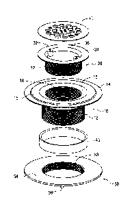
[00021] FIG. 1 is a top perspective exploded view of an embodiment of the
invention.
[00022] FIG. 2 is a bottom perspective exploded view thereof.
[00023] FIG. 3 is a front elevational cross-sectional exploded view
thereof.
[00024] FIG. 4 is a front elevational cross-sectional assembled view
thereof.
DETAILED DESCRIPTION OF EXEMPLARY EMBODIMENT(S)
[00025] Before describing in detail exemplary embodiments that accord with the
present invention, it should be observed that the embodiments reside primarily
in
combinations of apparatus components and processing steps related to
implementing a
compression drain for use with a preformed floor in which the height of the
drain grate
can be adjusted relative to said floor, and which positively locates the drain
housing
relative to the subfloor/waste water drain pipe. Accordingly, the apparatus
and method
components have been represented where appropriate by conventional symbols in
the
drawings, showing only those specific details that are pertinent to
understanding the
embodiments of the present invention so as not to obscure the disclosure with
details that
will be readily apparent to those of ordinary skill in the art having the
benefit of the
description herein.
[00026] In this document, relational terms, such as "first" and "second,"
"top" and
"bottom," and the like, may be used solely to distinguish one entity or
element from
another entity or element without necessarily requiring or implying any
physical or
logical relationship or order between such entities or elements. The terms
"comprises,"
"comprising," or any other variation thereof are intended to cover a non-
exclusive
inclusion, such that a process, method, article, or apparatus that comprises a
list of
elements does not necessarily include only those elements, but may include
other
elements not expressly listed or inherent to such process, method, article or
apparatus.
The term "plurality of" as used in connection with any object or action means
two or
more of such objects or actions. A claim element proceeded by the article "a"
or "an"
3
CA 02836429 2013-12-12
does not, without more constraints, preclude the existence of additional
identical
elements in the process, method, article or apparatus that includes the
element. The term
"tile" also encompasses "stone" and/or "marble." The term "tiled" means any
surface
having tile, stone, and/or marble applied thereon. The term "sidewall," in
relation to a
shower module, means any vertical surface rising above the floor of the shower
module
along one or more peripheral edges and may be any height or any width,
including,
without limitation, an integrated curb. The term "shower enclosure space"
refers to the
volume defined by the framed-out walls, the area where the shower door or
access area
will reside, the bathroom sub-floor, and the ceiling.
[00027] FIGs 1-4 illustrate the preferred form of the invention. It is to
be
understood, however, that this invention is not limited to the particular
structures, process
steps or materials disclosed herein, but is intended to encompass equivalents
thereof as
would be recognized by those of ordinary skill in the relevant arts.
Therefore, it is to be
understood that terminology used herein is employed for the purpose of
describing
particular disclosed examples of the invention only, and is not intended to
limit the scope
of the appended claims.
[00028] A drain in accordance with this invention is shown in FIGS 1-4,
wherein
drain body 10 is comprised of a cylindrical, externally threaded, lower
section 12 and an
upper annular flange 14. Flange 14 may include a frustro-conically tapered
section 16. A
portion of the interior of lower section 12 consists of screw threads 18, and
the remaining
portion thereof comprises a shoulder 20 below screw threads 18 and a smooth
cylindrical
wall section 21 which is adapted to receive a waste pipe W emanating from
subfloor S.
Shoulder 20 acts as a stop against the upper end of waste pipe W so as to
positively
position drain body 10 relative to subfloor S.
[00029] Preferably, a drain of this invention is adapted to be used with a
preformed
shower pan floor or other surface, which may be formed integrally with, or
assembled
post-manufacture (e.g. in factory or in the field) as part of a waterproof
pan, as known to
those of skill in the art. Pan floor 35 defines, or is modified to include, an
aperture 35
4
CA 02836429 2013-12-12
therein through which drain body 12 is adapted to be placed. A gasket 45, made
out of
any suitable material such as rubber, may be used to line the aperture 35 in
pan floor 35,
and be received about the exterior surface 17 of drain body 12. Preferably,
the height of
the gasket 45 corresponds substantially to the thickness of pan floor 35. A
top edge 45 of
gasket 45 may be chamfered so as to provide a nestable surface on which a
correspondingly tapered lower surface of flange 14 may sealingly mate.
[00030] Nut 50 is used to compress flange 14 of drain body 10 against an
upper
surface of pan floor 35, which may or may not define a corresponding annular
recess
within which flange 14 may nest. Flange 54 of nut 50 bears against a bottom
surface of
pan floor 35 to thereby compress drain body 10 in corresponding fashion
against the top
surface of pan floor 35. Lugs 59, or any other suitable structure, may be
employed to
engage a pipe wrench or other tool when tightening nut 50 to drain body 10.
[00031] A drain top 40, which may be of any type, including cylindrical,
square or
any other shape, apertured or not, is supported by drain top support 30. Drain
top support
30 includes a lower cylindrical section 32 defining screw threads on at least
a portion
thereof adapted to mate with corresponding screw threads 18 in drain body 10.
In this
way, support 30 can be raised or lowered so as to adjust the height of drain
top 40 relative
to the top surface of pan floor 35 or any covering (e.g. flooring material)
thereon. Drain
top 40 may be connected to support 30 by any suitable means, such as screws
received in
threaded bosses 39 defined by support 30. A frustro-conically tapered section
36 may be
employed adjacent upper flange 34 of support 30. Flange 34 may further define
a
recessed groove in which drain top 40 may fit.
[00032] As best seen in FIG. 4, when assembled, the drain of this invention
connects within aperture 35 in pan floor 35 by tightening nut 50 about the
screw threads
on lower section 12 of drain body 10 (and optional gasket 45 may also be
utilized), where
after support 30 is threaded to screw threads 18 of drain body 10 to a
distance which
renders the top surface of drain top 40 approximately coplanar with the
surrounding
surface, such as flooring tile 70. It is contemplated, however, that there
will be
CA 02836429 2013-12-12
installations where no flooring material is employed on pan floor 35 such that
support 30
should be adjusted so as to position the top surface of drain top 40
substantially coplanar
with the top surface of pan floor 35.
[00033] In the installation shown in FIG. 4, however, an insulated membrane
such
as rubber membrane 74 may be used, which membrane defines a central aperture
which
is concentric and coincides substantially with shoulder 15 of flange 14, said
shoulder
defined by a recessed groove in flange 14. In this way, the top surface of
flange 14
radially inwardly from shoulder 15 is substantially coplanar with the top
surface of the
membrane 74. Thereafter, an adhesive material 76, such as an epoxy adhesive or
other
thin set mortar, is applied above membrane 74 and flange 14 and under the
underside of
flange 34 of support 30 to provide a seal thereafter, flooring material 70
such as flooring
tile may be applied, and grouted if desired around the perimeter of drain top
40 and/or
flange 34.
[00034] Flange 34 of support 30 may be formed to define a lower surface
having a
taper 34 relative to horizontal which is in part parallel with the frustro-
conical recess 16
of drain body 12 when support 30 is threadingly engaged within threads 18 of
drain body
12. In this way, a gap is created, as seen in FIG. 4, in which sealing
material 76 such as
epoxy adhesive can be inserted to provide a waterproof joint. Surfaces 34 and
16 need
not be parallel to accomplish the desired result of defining a gap in which
sealing
material 76 may be placed.
[00035] The various components of the drain assemblies of this invention
may be
fabricated of any suitable material, such as metal, hardened resin, foam, or
the like. In
addition, drain top 40 may be made in any shape, the circular shape shown in
the
drawings being merely by way of example but not limitation. Drain top 40 may
be
apertured as shown, or may be solid, and mounted to support 30 in such a way
as to
provide a gap (not shown) between flange 34 and a bottom surface of drain top
40
through which water may drain. Drain top 40 may be adapted to receive tile or
other
flooring material thereon, or may be uncovered or partially covered.
6
CA 02836429 2013-12-12
[00036] Benefits,
other advantages, and solutions to problems have been described
above with regard to specific embodiments of the present invention. However,
the
benefits, advantages, solutions to problems, and any element(s) that may cause
or result
in such benefits, advantages, or solutions to become more pronounced are not
to be
construed as a critical, required, or essential feature or element of any or
all the claims.
The invention is defined solely by the appended claims including any
amendments made
during the pendency of this application and all equivalents of those claims as
issued.
7