Note: Descriptions are shown in the official language in which they were submitted.
CA 02836542 2013-11-18
WO 2012/158755
PCT/US2012/038060
1
TITLE: MULTI-LOOP ADJUSTABLE KNOTLESS ANCHOR ASSEMBLY,
ADJUSTABLE CAPTURE MECHANISM, AND METHOD FOR REPAIR
BACKGROUND OF THE INVENTION
1. Field of the Invention
The present invention relates to devices or methods used in tissue repair,
more
particularly, devices and methods for attachment of biological tissue (i.e.,
tendons or
ligaments) to a bone mass.
2. Description of the Related Art
Soft tissues, such as tendons and ligaments, generally are attached to bone by
small collageaous fibers. These connections are strong but permit the tendons
and
ligaments to be flexible. When a tissue, or a portion of a tissue, is torn
away from the
bone and requires repair, a surgeon is often required to repair the detached
soft tissue
with sutures, which are passed through bone tunnels and tied. A number of
devices
have been developed for securing a ligament or tendon to a bone mass. These
devices
can be used in place of bone tunneling techniques. These attachment devices
are
usually anchor element through extensive surgical incisions and, in some
circumstances, by arthroscopic surgical techniques. The placement of bone
tunnels for
repair can be difficult and generally require large open incisions. Recently,
through the
advent of arthroscopic surgery, where the surgeon looks into a joint cavity
with an
arthroscope, there has been a trend to repair soft tissues back to bone
through small
incisions called portals. The unique free loop knotless suture anchor
assemblies
described herein facilitate this difficult and precise procedure.
A variety of devices are available for attaching objects to bone, such as
screws,
staples, cement, suture anchors, and sutures alone. These devices have been
used to
attach soft tissue, such as ligaments, tendons, muscles, as well as objects
such as
prostheses, to bone. A suture anchor assembly is a device, which utilizes
small anchors
with suture materials attached thereto. A device, such as a screw, is inserted
into the
bone mass and anchored in place. After insertion of the anchor, the attached
suture is
passed through the tissue to be repaired. The tying of a knot in the suture is
then
CA 02836542 2013-11-18
WO 2012/158755
PCT/US2012/038060
2
required to secure the tissue to the bone. The process of passing the anchored
suture
through the soft tissue and tying a knot is time consuming and difficult to
undertake in
the tight space encountered during arthroscopic surgery and sometimes even in
conventional open surgery.
Knotless anchor assemblies have been popular and are embodied in a number of
prior patents such as U.S. Patent No. 6,045,574 wherein there is provided an
assembly
with an anchor means having a snag means, and a hollow sleeve element with a
loop
suture element attached thereto, wherein the snag means captures a loop suture
element of the hollow sleeve element to draw tissue into secure attachment
with a
bone mass.
However, difficulties still exist and the present invention attempts to
address
these with a method and apparatus for knotless suture anchoring.
CA 02836542 2013-11-18
WO 2012/158755 PCT/US2012/038060
3
SUMMARY OF THE INVENTION
It is, therefore, an object of the present invention to provide a suture
anchoring
system including a first anchor with an anchor suture loop secured thereto and
a tissue
=
suture loop.
It is also an object of the present invention to provide a suture anchoring
system wherein the tissue suture loop includes a one-way sliding, locking knot
with a
tensioning suture component extending therefrom.
It is another object of the present invention to provide a suture anchoring
system wherein the anchor suture loop includes a one-way sliding, locking knot
with a
tensioning suture component extending therefrom.
It is a further object of the present invention to provide a suture anchoring
system wherein the first anchor is an elongated member having a first end and
a second
end, the first end including a first aperture and the second end includes a
second
aperture.
It is also an object of the present invention to provide a suture anchoring
system wherein the anchor suture loop is secured to a first end of the first
anchor and a
second end of the first anchor includes a snag member shaped and dimensioned
for
engaging a free end of the anchor suture loop.
It is another object of the present invention to provide a suture anchoring
system including a sleeve shaped and dimensioned for receiving the first
anchor.
It is a further object of the present invention to provide a suture anchoring
system wherein the first anchor includes an external surface with means for
engaging
with a recess of the sleeve.
It is also an object of the present invention to provide a suture anchoring
system including a mounting sleeve having an open distal end and an open
proximal
end defining a passageway therethrough, a first elongated member with an
anchor
suture secured thereto, and a tissue suture loop.
It is another object of the present invention to provide a suture anchoring
system including a second elongated member secured to the anchor suture.
It is a further object of the present invention to provide a method for
securing
tissue including passing a tissue suture loop through the tissue such that
opposed first
CA 02836542 2013-11-18
WO 2012/158755
PCT/US2012/038060
4
and second loop sections are formed, passing an anchor suture through first
and second
openings respectively defined by the opposed first and second loop sections,
capturing
the anchor suture after passing through the first and second openings with a
first
elongated member attached to the anchor suture, and securing the first
elongated
member attached to the anchor suture to a desired anchor hole in an anatomical
site.
It is also an object of the present invention to provide a method for securing
tissue wherein the anatomical site is a bone surface.
It is another object of the present invention to provide a method for securing
tissue wherein a first end of the anchor suture is secured to the first
elongated member
and a second end of the anchor suture is secured to a second elongated member,
and
the first and second elongated members are secured with in a mounting sleeve
at an
anchor hole at the anatomical site.
It is a further object of the present invention to provide a method for
securing
tissue wherein the mounting sleeve includes an open proximal end and an open
distal
end defining a cylindrical passageway and allowing access therethrough. The
method
further includes the step of passing both the first and second elongated
members
through the passageway and into the small cavity defined by a bottom of the
anchor
hole, and orienting the first and second anchors transversely to a
longitudinal axis of
the cylindrical mounting sleeve to thereby lock the first and second elongated
members in position.
It is also an object of the present invention to provide a method for securing
tissue wherein a first end of the anchor suture is secured to first end of the
first
elongated member and a free end of the anchor suture is captured by a snag
member of
the first elongated member prior to securing the first elongated member.
It is another object of the present invention to provide a method for securing
tissue further including the step of tensioning either the tissue suture loop
or the
anchor suture.
It is a further object of the present invention to provide a method for
securing
tissue further including the step of tensioning the tissue suture loop.
CA 02836542 2013-11-18
WO 2012/158755
PCT/US2012/038060
It is also an object of the present invention to provide a method for securing
tissue wherein the anchor suture is an anchor suture loop and the method
includes the
further step of tensioning the anchor suture loop.
It is another object of the present invention to provide a method for securing
tissue further including a cylindrical anchor mounting sleeve shaped and
dimensioned
for receiving the first elongated member, the cylindrical anchor mounting
sleeve
includes an open proximal end and an open distal end defining a passageway and
allowing access therethrough, wherein the cylindrical anchor mounting sleeve
is
positioned within the anatomical site.
It is a further object of the present invention to provide a method for
securing
tissue further including the step of passing the first elongated member
through the
passageway and into the small cavity defined by a bottom of the anchor hole,
and
orienting the first anchor transversely to a longitudinal axis of the
cylindrical anchor
mounting sleeve to thereby lock the bone anchor in position.
Other objects and advantages of the present invention will become apparent
from the following detailed description when viewed in conjunction with the
accompanying drawings, which set forth certain embodiments of the invention.
CA 02836542 2013-11-18
WO 2012/158755
PCT/US2012/038060
6
BRIEF DESCRIPTION OF THE DRAWINGS
Figure 1 is a perspective view of the adjustable suture loop.
Figure 2 is a perspective view of the bone anchor.
Figures 3, 4 and 5 show the steps of the present method.
Figure 6 shows bone anchors deployed at different depths within a bone mass
in accordance with the present invention.
Figures 7, 8 and 9 are respectively a front plan view, a side plan view and a
perspective view of an anchor member in accordance with an alternate
embodiment.
Figures 10A-C and 11A-D show alternate embodiments for securing an anchor
suture loop to the anchor member shown in Figures 7, 8 and 9.
Figures 12, 13 and 14 show the steps of the present method as applied using
the
anchor member shown in Figures 7, 8 and 9.
Figures 15, 16 and 17 are respectively a front plan view, a side plan view and
a
perspective view of an anchor member in accordance with yet another alternate
embodiment.
Figures 18, 19 and 20 show the steps of the present method as applied using
the
anchor member shown in Figures 15, 16 and 17.
Figures 21 and 22 disclose an alternate embodiment in accordance with the
present invention.
Figure 23, 24, 25 and 26 show an alternate system associated methodology in
accordance with the present invention.
CA 02836542 2015-06-02
7
DESCRIPTION OF THE PREFERRED EMBODIMENTS
The detailed embodiments of the present invention are disclosed herein. It
should be understood, however, that the disclosed embodiments are merely
exemplary
of the invention, which may be embodied in various forms. Therefore, the
details
disclosed herein are not to be interpreted as limiting, but merely as a basis
for teaching
one skilled in the art how to make and/or use the invention.
In accordance with the present invention, and with reference to Figures 1 to
6,
the present procedure is achieved using existing bone anchors 1, for example,
the
BIOKNOTLESSTm/LUPINETm bone anchors of DePuy Mitek as described in U.S.
Patent Nos. 5,709,708 and 5,782,864, which are shown in Figures 2, 4, 5 and 6.
Each of the bone anchors 1 preferably employed in accordance with the present
invention is composed of an anchor member 10 having a first end 20 and a
second end
22. A suture element in the form of an anchor suture loop 12 is provided and
can be
fixedly secured at the first end 20 and/or the second end 22 of the anchor
member 10
such that the anchor suture loop 12 includes a fixed end 24 directly secured
at the first
end 20 of the anchor member 10 and a free end 26 that may be freely
manipulated in
accordance with the present invention. Conversely, the anchor suture loop may
be
attached to any desired location on the anchor member or separate and free
from the
anchor member. It is also appreciated, the anchor suture loop can be secured
by a knot
or just passed through the aperture 52. Also, the anchor suture loop 12 can be
attached
with a sliding, locking knot that allows adjustability to the size of loop 12,
which can be
used to tension the repair. In accordance with a preferred embodiment, the
anchor
suture loop 12 is retained in an aperture 52 formed adjacent the first end 20
of the
anchor member 10, although it is appreciated other attachment arrangements and
mechanisms may be employed.
The second end 22 of the anchor member 10 includes a snag member 14 shaped
and dimensioned for engaging the free end 26 of the anchor suture loop 12. In
accordance with a preferred embodiment, the snag member 14 is a notch formed
in the
second end 22 of the anchor member 10. Although the embodiment disclosed
herein
employs a snag member in the form of a notch at the second end of the anchor
CA 02836542 2013-11-18
WO 2012/158755
PCT/US2012/038060
8
member, it is appreciated other snag member structures and positions may be
employed as shown in U.S. Patent Nos. 5,709,708 and 5,782,864.
The anchor member 10 also includes, if desired, lateral extending prongs 16,
18
shaped and dimensioned to facilitate the attachment of the anchor member 10 to
a
bone mass 28. The anchor member 10 is also provided with a selectively
detachable
deployment arm 50 that is used in the manipulation of the anchor member 10 as
it is
deployed as discussed below in greater detail. It is appreciated the bone
anchor 1 can
also contain, or be configured with, umbrella spokes, it can contain threads,
be
expandable, or have any other type of engaging features on its exterior for
secure
attachment with a bone mass. All of these exterior attachment features are
known to
the industry and may be readily applied to the bone anchor of the present
invention.
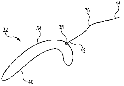
Briefly, the present invention achieves secure, tensioned attachment of soft
tissue 30 to a bone mass 28 using a bone anchor 1 as described above in
conjunction
with an adjustable suture loop 32 composed of loop member 34 with a tensioning
suture component 36 extending therefrom and coupled thereto through the
creation of
a slip (or sliding) knot 38. The adjustable suture loop 32 is preferably
flexible and/or
inelastic, and may be prepared with a pre-tied sliding knot. The free end of
the
adjustable suture loop 32, that is, the second end 44 of the tensioning suture
component 36, is left in place to allow for additional tensioning as is
discussed below in
greater detail. It is appreciated, the tensioning suture component, as shown
in Figure 1,
can be composed of more than one suture and may have multiple free ends.
The adjustable suture loop 32 is composed of one or more strands of suture 40.
The adjustable suture loop 32 includes a first segment and a second segment
tied so as
to form a loop member 34 and one or more tensioning suture components 36
extending from the loop member 34. As such, the tensioning suture component
36, as
shown in Figure 1, may be composed of more than one suture depending upon the
number of strands of suture used in the construction of the adjustable suture
loop.
The tensioning suture component 36 includes a first end 42 and a second end
44. The
first end 42 is secured to the loop member 34 at the sliding, locking knot 38
defining
the loop member 34, while the second end 44 freely extends therefrom for
manipulation by the medical practitioner as discussed below in greater detail.
CA 02836542 2013-11-18
WO 2012/158755
PCT/US2012/038060
9
The adjustable suture loop 32 is constructed by tying the first segment and
the
second segment of the strand of suture 40 with a sliding, locking knot 38. As
is
appreciated, various knot types and a sliding, locking knot is formed in the
manner
disclosed in Arthroscopic Knot Tying, Frank G. Alberta, et al. (Arthroscopic
Knot
Tying Chapter 4: pp. 29-38); Arthroscopic knot-tying techniques, Eric R
McMillan et
al. (An Atlas of Shoulder Arthroscopy Imhoff AB Tucker IB Eu EH (eds) pp81-
95);
and Arthroscopic Knots: Determining the Optimal Balance of Loop Security and
Knot
Security, Ian K. Y. Lo, et al. (The Journal of Arthroscopic and Related
Surgery, Vol
20, No 5 (May-June). 2004: pp. 489-502). By constructing the adjustable
flexible suture
loop 32 with a sliding, locking knot 38, one can alter the size of the loop
member 34
by pulling upon the tensioning suture component 36, which functions by pulling
a
portion of the suture strand 40 through the sliding, locking knot 38 and
ultimately
reducing the size of the loop member 34 while increasing the length of the
tensioning
suture component 36.
In accordance with the present method, the adjustable suture loop 32 is first
passed through the soft tissue 30 one wishes to secure to a bone mass 28.
Referring to
Figure 3, the adjustable suture loop 32, in particular, the loop member 34
thereof is
drawn through the soft tissue 30 with a surgical needle. A variety of suture
passing
methods can be used such as arthroscopic suture passers, arthroscopic suture
shuttling
devices or suture, or the like. The loop member 34 is passed through the soft
tissue 30,
one or more times, such that opposed first and second loop sections 46, 48 are
formed
when the loop member 34 is effectively split into two sections by the soft
tissue 30;
that is, with the soft tissue 30 between the opposed loop sections 46, 48. In
particular,
the loop member 34 is pulled through the soft tissue 30 until the two loop
sections 46,
48 are of substantially the same size and in alignment. Pulling of the loop
member 34
through the tissue is preferably achieved using a "utility suture" in a manner
known to
those skilled in the art. It is appreciated the loop member 34 is relatively
long so that
the opposed loop sections 46, 48 may be brought outside of the joint under
repair. As
shown in Figures 2, 3 and 4, the tensioning suture component 36 of the
adjustable
suture loop 32 also extends from one of the loop sections 46 and is similarly
accessible
from outside of the joint under repair.
CA 02836542 2013-11-18
WO 2012/158755
PCT/US2012/038060
With the loop sections 46, 48 of the adjustable suture loop 32 outside of the
joint, and with reference to Figure 4, the anchor suture loop 12 of the anchor
member
10 is passed through the openings 51, 53 respectively defined by the opposed
first and
second loop sections 46, 48. That is, the free end 26 of the anchor suture
loop 12 is
drawn through the openings 51, 53 such that the anchor suture loop 12 is
intertwined
or linked with the opposed loop section 46, 48. In this arrangement, the
central
portion 60 of the loop member 34 between the loop sections 46, 48 is in direct
contact
with the soft tissue 30 securing the anchor suture loop 12 to the soft tissue
30 such that
the loop sections 46, 48 may simultaneously pull against the anchor suture
loop 12
without fear that the loop member 34 will become disengaged with the soft
tissue 30.
Thereafter, the free end 26 of the anchor suture loop 12 is captured by the
snag
member 14 of the anchor member 10; that is, the free end 26 of the anchor
sutilre loop
12 is captured, entangled, coupled to, or otherwise attached to the snag
member 14 at
the second end 22 of the anchor member 10 for manipulation of the anchor
suture
loop 12 and ultimately fixed attachment of the free end 26 of the anchor
suture loop 12
to the snag member 14 at the second end 22 of the anchor member 10 upon
deployment of the bone anchor 1 within the bone mass 28 to which the soft
tissue 30 is
secured. It is appreciated that if the snag member is not positioned at the
second end of
the anchor, which is possible as discussed above, the free end of the anchor
suture loop
would be fixed wherever the snag member is located.
With the anchor suture loop 12 passed through the openings 51, 53 defined by
the opposed first and second loop sections 46, 48 and the free end 26 of the
anchor
suture loop 12 captured by the snag member 14 at the second end 22 of the
anchor
member 10, the anchor suture loop 12 is linked to the loop member 34 and
ultimately
the soft tissue 30. Referring to Figure 5, the bone anchor 1 is then inserted
within an
anchor hole 54 preferably predrilled in the bone mass 28. It is appreciated,
the anchor
member 10 can also be pushed into or screwed into the bone mass 28, if
desired. In
accordance with the disclosed embodiment, the bone anchor 1 is inserted into
the hole
50 securing the two ends of the suture in the bone mass 28. It is appreciated;
the bone
anchor can be deployed by toggling, flipping, or the like. Alternatively, the
anchor
member may have a second hole or opening on its second end, and the suture
loop is
CA 02836542 2013-11-18
WO 2012/158755
PCT/US2012/038060
11
wrapped around the tip of the anchor member. It is also appreciated, a
mounting
sleeve may be inserted into the anchor hole and the anchor member secured
directly to
the mounting sleeve instead of the anchor hole. After the anchor member is
passed in
the hole or in a threaded anchor mounting sleeve, if desired, the anchor
member can be
rotated so it locks in place on the end of the anchor mounting sleeve. The
provision of
the sliding, locking knot on anchor suture loop allows for adjustment in the
size of this
loop. This adjustability is useful in several aspects of the surgical
procedure.
With the bone anchor 1 securely held within the drill hole 54, the loop member
34 is tensioned so as to reduce the size of the loop member 34 and draw the
soft tissue
toward the bone mass 28. In particular, the tensioning suture component 36 is
pulled
in a direction away from the loop member 34 causing the suture strand 40 to be
drawn
through the sliding, locking knot 38 reducing the size of the loop member 34
and
consequently drawing the soft tissue 30 toward the bone mass 28 since the size
of the
anchor suture loop 12 is fixed. The tensioning suture 36 is pulled and the
loop
member 34 size is reduced until such a time that the soft tissue 30 is fully
pulled
toward the bone mass 28. The procedure may be repeated depending upon the
needs
of the procedure. The excess suture material of the tensioning suture
component(s) 36
may then be cut away and the incision closed. With some anchor member designs,
additional tensioning can be achieved by pushing the anchor deeper into the
drill hole
after the loop is tensioned by the sliding, locking knot. Referring to Figure
6, it is also
appreciated the present invention allows for anchoring and soft tissue
attachment with
limited regard for the depth of the drilled hole or the depth of the bone
anchor within
the bone mass. This results from ability to draw the soft tissue 30 toward the
bone
anchor 1 and bone mass 28 under the control of the adjustable suture loop 32,
in
particular pulling of the tensioning suture component 36 which results in a
reduction
in the size of the loop member 34. Because the size of the loop member 34
dictates
how far the soft tissue 30 is pulled toward the bone mass 28/bone anchor 1, a
medical
practitioner can readily control the position of the soft tissue 30 relative
to the bone
mass 28/bone anchor 1.
As briefly discussed above, it is appreciated other bone anchor. structures
may
be employed in accordance with the present invention. Such a bone anchor is
CA 02836542 2013-11-18
WO 2012/158755
PCT/US2012/038060
12
disclosed with reference to Figures 7 to 14, and is used in conjunction with
the
adjustable suture loop described above.
The bone anchor 100 is composed of an anchor member 110 having a first end
120 and a second end 122. A suture element 112, in the form of an anchor
suture loop
is provided and can be fixedly secured at the anchor member 110 as discussed
below in
greater detail.
The anchor member 110 includes an elongated body 162. In accordance with a
preferred embodiment, the elongated body 162 is preferably, cylindrical
shaped, and
includes a rounded first end 120 and a rounded second end 122. The elongated
body
162 includes spaced first and second apertures 164, 166. The first and second
apertures
164, 166 are preferably positioned adjacent the first end 120 and the second
end 122 of
the elongated body 162, respectively. It is, however, appreciated other
aperture
positions are possible.
As with the prior embodiment, the anchor member 110 may also include, if
desired, lateral extending prongs shaped and dimensioned to facilitate the
attachment
of the anchor member 110 to a bone mass 128. The anchor member 110 is also
provided with a selectively detachable deployment arm 150 that is used in the
manipulation of the anchor member 110 as it is deployed as discussed below in
greater
detail.
The anchor suture loop 112 is coupled to the anchor member 110 by controlled
entanglement with the first and second apertures 164, 166 and the elongated
body 162
of the anchor member 110. For example, and in conjunction with a first manner
of
attachment, the anchor suture loop 112 is fixedly secured at the first
aperture 164 in a
manner similar to the embodiment disclosed with reference to Figures 1 to 6.
Considering such an attachment mechanism, the anchor suture loop 112 may be
thought of as including a fixed (or first) end 124 directly secured at the
first aperture
164 of the anchor member 110 and a free (or second) end 126 that may be freely
manipulated for passage through the second aperture 166. When it is desired to
entangle the anchor suture loop 112 with the adjustable suture loop 132, the
free end
126 of the anchor suture loop 112 is passed through the second aperture 166
creating an
entanglement loop 170 at the second aperture 166 opposite the entry point for
the free
CA 02836542 2013-11-18
WO 2012/158755
PCT/US2012/038060
13
end 126 of the anchor suture loop 112, as well as an engagement loop 172
between the
first aperture 164 and the second aperture 166. The entanglement loop 170 is
then
looped around the elongated body 162 adjacent the second end 122 of the anchor
member 110 effectively locking the anchor suture loop 112 in position when
tension is
applied to the engagement loop 172 formed by the anchor suture loop 112
between the
first aperture 164 and the second aperture 166.
In accordance with an alternate attachment mechanism, the anchor suture loop
112' may be initially separate from the anchor member 110' and secured thereto
by
looping the anchor suture loop 112' over the elongated body 162' at both the
first end
120' and the second end 122' of the anchor member 110'. Considering the anchor
suture loop 112' as being drawn taut and, therefore, including a first suture
end 124'
and a second suture end 126', the first suture end 124' is passed through the
first
aperture 164' creating an entanglement loop 170a' at the first aperture 164'
opposite
the entry point for the first suture end 124' of the anchor suture loop 112'.
The
entanglement loop 170a' is then looped around the elongated body 162' adjacent
the
first end 120' of the anchor member 110' effectively locking the anchor suture
loop
112' in position when tension is ultimately applied to engagement loop 172'
formed by
the anchor suture loop 112' between the first aperture 164' and the second
aperture
166'. The second suture end 126' is then passed through the second aperture
166'
creating an entanglement loop 170b' at the second aperture 166' opposite the
entry
point for the second suture end 126' of the anchor suture loop 112'. The
entanglement
loop 170b' is then looped around the elongated body 162' adjacent the second
end 122'
of the anchor member 110'. The application of tension effectively locks the
anchor
suture loop 112' in position when tension is ultimately applied to engagement
loop
172' formed by the anchor suture loop 112 between the first aperture 164' and
the
second aperture 166', that is, the entanglement loops 170a', 170b' at the
first and
second ends 120', 122' of the anchor member 110' wrap thereabout in a manner
gripping the anchor member 110'. It is appreciated as discussed below in
accordance
with an alternate embodiment that the anchor suture loop may also be provided
as an
adjustable loop with a sliding, locking knot and tensioning suture.
CA 02836542 2013-11-18
WO 2012/158755
PCT/US2012/038060
14
In accordance with the present method as applied in conjunction with the
anchor suture loop attachment methodology described with reference to Figures
10A-
C to (those skilled in the art would appreciate the utilization of the
alternative anchor
suture loop 112' attachment methodology described with reference to Figures
11A-
1ID would be the same with the exception of the attachment of the first suture
end
124' of the anchor suture loop 112' to the first end 120' of the anchor member
1101,
the adjustable suture loop 132 is first passed through the soft tissue 130 one
wishes to
secure to a bone mass 128. Referring to Figure 12, the adjustable suture loop
132, in
particular, the loop member 134 thereof is drawn through the soft tissue 130
with a
surgical needle. The loop member 134 is passed through the soft tissue 130,
one or
more times, such that opposed first and second loop sections 146, 148 are
formed when
the loop member 134 is effectively split into two sections by the soft tissue
130; that is,
with the soft tissue 130 between the opposed loop sections 146, 148. In
particular, the
loop member 134 is pulled through the soft tissue 130 until the two loop
sections 146,
148 are of substantially the same size and in alignment. It is appreciated the
loop
member 34 is relatively long so that the opposed loop sections 146, 148 may be
brought outside of the joint under repair. As shown in Figures 12, 13 and 14,
the
tensioning suture component 136 of the adjustable suture loop 132 also extends
from
one of the loop sections 146 and is similarly accessible from outside of the
joint under
repair.
With the loop sections 146, 148 of the adjustable suture loop 132 outside of
joint, and with reference to Figure 13, the anchor suture loop 112 of the
anchor
member 110 is entangled with the adjustable suture loop 132. In particular,
the free
end 124 of the anchor suture loop 112 is passed through the openings 151, 153
respectively defined by the opposed first and second loop sections 146, 148.
That is,
the free end 126 of the anchor suture loop 112 is drawn through the openings
151, 153
such that the anchor suture loop 112 is intertwined with the opposed loop
section 146,
148. In this arrangement, the central portion 160 of the loop member 134
between the
loop sections 146, 148 is in direct contact with the soft tissue 130 securing
the anchor
suture loop 112 to the soft tissue 130 such that the loop sections 146, 148
may
CA 02836542 2013-11-18
WO 2012/158755
PCT/US2012/038060
= 15
simultaneously pull against the anchor suture loop 112 without fear that the
loop
member 134 will become disengaged with the soft tissue 130.
Thereafter, the free end 126 of the anchor suture loop 112 is captured by
passing the free end 126 of the anchor suture loop 112 through the second
aperture 166
creating an entanglement loop 170 at the second aperture 166 opposite the
entry point
for the free end 126 of the anchor suture loop 112, as well as an engagement
loop 172
between the first aperture 164 and the second aperture 166. The entanglement
loop
170 is then looped around the elongated body 162 adjacent the second end 122
of the
anchor member 110 effectively locking the anchor suture loop 112 in position
when
tension is applied to engagement loop 172 formed by the anchor suture loop 112
between the first aperture 164 and the second aperture 166.
Ultimately, fixed attachment of the free end 126 of the anchor suture loop 112
at the second end 122 of the anchor member 110 is achieved upon deployment of
the
bone anchor 100 within the bone mass 128 to which the soft tissue 130 is
secured.
With the anchor suture loop 112 passed through the openings 151, 153 defined
by the
opposed first and second loop sections 146, 148 and the free end 126 of the
anchor
suture loop 112 secured at the second end 122 of the anchor member 110, the
anchor
suture loop 112 is tied to the loop member 134 and ultimately the soft tissue
130.
Referring to Figure 14, the bone anchor 100 is then inserted within an anchor
hole 154
preferably predrilled in the bone mass 128 and the adjustable suture loop 132
is
tightened as discussed above with regard to Figures 1 to 6.
In accordance with an alternate embodiment, as shown with reference to
Figures 15-20, a bone screw 280 is used in conjunction with a bone anchor 200
for
securely implanting of the bone anchor 200 within the bone mass 228. In
particular,
the bone anchor 200 is substantially the same as described above with
reference to
Figures 7-14, with the exception the external surface 282 of the anchor member
210 is
provided with threading 284 shaped and dimensioned for engagement with
threading
286 formed in an anchor recess 288 of the bone screw 280.
The bone anchor 200 is composed of an anchor member 210 having a first end
220 and a second end 222. A suture element 212, in the form of an anchor
suture loop
CA 02836542 2013-11-18
WO 2012/158755
PCT/US2012/038060
16
is provided and can be fixedly secured to the anchor member 210 as discussed
below in
greater detail.
The anchor member 210 includes an elongated body 262. The elongated body
262 is preferably cylindrical shaped and includes a rounded first end 220 and
a rounded
second end 222. The elongated body 262 includes spaced first and second
apertures
264, 266. The first and second apertures 264, 266 are preferably positioned
adjacent the
first end 220 and the second end 222 of the elongated body 262, respectively.
The external surface 282 of the elongated body 262 is provided with threading
284 shaped and dimensioned for threaded engagement with a threaded anchor
recess
288 formed in the bone screw 280. The anchor member 210 is also provided with
a
selectively detachable deployment arm 250 that is used in the manipulation of
the
anchor member 210 as it is deployed as discussed below in greater detail.
The anchor suture loop 212 is coupled to the anchor member 210 by controlled
entanglement with the first and second apertures 264, 266 and the elongated
body 262
of the anchor member 210 as discussed above with regard to Figures 10A-C and
11A-
D. For the purposes of describing this embodiment, the coupling of the anchor
suture
loop 212 with the anchor member 210 is shown as described with reference to
Figures
10A-C, although it is appreciated other attachment mechanisms (for example, as
shown
with reference to Figures 11A-D) may be employed.
In accordance with the present method, the adjustable suture loop 232 is first
passed through the soft tissue 230 one wishes to secure to a bone mass 228.
Referring
to Figure 18, the adjustable suture loop 232, in particular, the loop member
234 thereof
is drawn through the soft tissue 230 with a surgical needle. The loop member
234 is
passed through the soft tissue 230, one or more times, such that opposed first
and
second loop sections 246, 248 are formed when the loop member 234 is
effectively split
into two sections by the soft tissue 230; that is, with the soft tissue 230
between the
opposed loop sections 246, 248. In particular, the loop member 234 is pulled
through
the soft tissue 230 until the two loop sections 246, 248 are of substantially
the same size
and in alignment. It is appreciated the loop member 234 is relatively long so
that
opposed loop sections 246, 248 may be brought outside of the joint under
repair. As
shown in Figures 18, 19 and 20, the tensioning suture component 236 of the
adjustable
CA 02836542 2013-11-18
WO 2012/158755
PCT/US2012/038060
17
suture loop 232 also extends from the one of the loop sections 246 and is
similarly
accessible from outside of the joint under repair.
With the loop sections 246, 248 of the adjustable suture loop 232 outside of
joint, and with reference to Figures 18 and 19, the anchor suture loop 212 of
the
anchor member 210 is entangled with the adjustable suture loop 232. In
particular, the
free end 226 of the anchor suture loop 212 is passed through the openings 251,
253
respectively defined by the opposed first and second loop sections 246, 248.
That is,
the free end 226 of the anchor suture loop 212 is drawn through the openings
251, 253
such that the anchor suture loop 212 is intertwined with the opposed loop
sections
246, 248. In this arrangement, the central portion 260 of the loop member 234
between the loop sections 246, 248 is in direct contact with the soft tissue
230 securing
the anchor suture loop 212 to the soft tissue 230 such that the loop sections
246, 248
may simultaneously pull against the anchor suture loop 212 without fear that
the loop
member 234 will become disengaged with the soft tissue 230.
Thereafter, the free end 226 of the anchor suture loop 212 is captured by
passing the free end 226 of the anchor suture loop 212 through the second
aperture 266
creating an entanglement loop 270 at the second aperture 266 opposite the
entry point
for the free end 226 of the anchor suture loop 212, as well as an engagement
loop 272
between the first aperture 264 and the second aperture 266. The entanglement
loop
270 is then looped around the elongated body 262 adjacent the second end 222
of the
anchor member 210 effectively locking the anchor suture loop 212 in position
when
tension is applied to engagement loop 272 formed by the anchor suture loop 212
between the first aperture 264 and the second aperture 266.
Ultimately, fixed attachment of the free end 226 of the anchor suture loop 212
at the second end 222 of the anchor member 210 is achieved upon deployment of
the
bone anchor 200 within the bone screw 280, and ultimately the bone mass 228,
to
which the soft tissue 230 is secured. With the anchor suture loop 212 passed
through
the openings 251, 253 defined by the opposed first and second loop sections
246, 248
and the free end 226 of the anchor suture loop 212 secured at the second end
222 of the
anchor member 210, the anchor suture loop 212 is tied to the loop member 234
and
ultimately the soft tissue 230. Referring to Figure 20, the bone anchor 200 is
then
CA 02836542 2013-11-18
WO 2012/158755
PCT/1.152012/038060
18
inserted within the threaded anchor recess 288 formed in the bone screw 280
previously applied to the bone mass 228 and the adjustable suture loop 232 is
tightened
as discussed above with regard to Figures 1 to 6. It is appreciated as
discussed below
in accordance with an alternate embodiment that the anchor suture loop may
also be
provided as an adjustable loop with a sliding, locking knot and tensioning
suture.
With reference to Figures 21 and 22, an alternate embodiment is disclosed that
is similar to that disclosed with reference to Figures 15-20. In the alternate
embodiment, the distal end 290 of the cylindrical anchor mounting sleeve or
bone
screw 280 is open, allowing access to the internal bone mass; that is, the
bone screw
280 is in the form of an open cylindrical anchor mounting sleeve with or
without
external threading. Any fixation method can be utilized to affix the anchor
mounting
sleeve to the bone mass. It is appreciated the open cylindrical anchor
mounting sleeve
provides an anchor recess (or anchor passageway 288 in accordance with such an
embodiment) extending from the proximal end 292 of the open cylindrical anchor
mounting sleeve 280 to the distal end 290 of the open cylindrical anchor
mounting
sleeve 280. As will be explained below, the bone anchor is secured in a
different
manner, to effectuate tissue repair, from that disclosed above and threading
on the
bone anchor is therefore not necessary. As such, reference numerals used in
conjunction with Figures 15-20 have also been used, where possible, based upon
the
similarity of the two embodiments.
The anchor passageway 288, in the open cylindrical anchor mounting sleeve
280, allows for capture of the bone anchor 200 on the distal end 290 of the
open
cylindrical anchor mounting sleeve 280 within a small cavity 294 defined by
the
bottom 296 of the anchor hole 254 and the distal end 290 of the open
cylindrical
anchor mounting sleeve 280. The bone anchor 200 is passed through the anchor
passageway 288 with the longitudinal axis of the bone anchor 200 aligned
substantially
parallel with the longitudinal axis of the open cylindrical anchor mounting
sleeve 280
(see Figure 21). Once the bone anchor 200 has passed fully through the anchor
passageway 288 and into the small cavity 294 defined by the bottom 296 of the
anchor
hole 254 and the distal end 290 of the open cylindrical anchor mounting sleeve
280, the
bone anchor 200 may be oriented to extend transversely to the longitudinal
axis of the
CA 02836542 2013-11-18
WO 2012/158755
PCT/US2012/038060
19
open cylindrical anchor mounting sleeve 280 and thereby lock the bone anchor
200 in
position due to the fact the length of the bone anchor 200 is greater than the
diameter
of the anchor passageway 288 or alternatively, the bone anchor 200 is shaped
in such a
manner, for example, a wedge-shaped suture anchor, such as those sold by Mitek
Surgical Products, Inc. and depicted in U.S. Patent No. 5,683,418, and having
an edge
shaped in such a manner to capture the distal end of the open cylindrical
anchor
mounting sleeve 280 (see Figure 22). It is also appreciated, the internal
structure of the
bone mass is not very dense and the bone anchor 200 may actually be pushed
into, and
manipulated within the bone mass for orientation as shown in Figure 22,
thereby
obviating the need for a deep hole or a hole extending below the distal end of
the open
cylindrical anchor mounting sleeve 280.
As with the embodiment disclosed with reference to Figures 15-20, once the
bone anchor 200 is locked in position within the small cavity 294, the
adjustable suture
loop 232 may be tightened as discussed above with regard to Figures 1 to 6.
In accordance with yet another embodiment of the present invention, and with
reference to Figures 23-26, an alternate method and apparatus is disclosed
wherein first
and second bone anchors 300a, 300b are used in securing of tissue. As with the
embodiment of Figure 21 and 22, the distal end 390 of the cylindrical anchor
mounting
sleeve or bone screw 380 is open, allowing access to the internal bone mass;
that is, the
bone screw 380 is in the form of an open cylindrical anchor mounting sleeve
with or
without external threading. Any fixation method can be utilized to affix the
anchor
mounting sleeve to the bone mass. The open cylindrical anchor mounting sleeve
380
provides an anchor passageway 388 extending from the proximal end 392 of the
open
cylindrical anchor mounting sleeve 380 to the distal end 390 of the open
cylindrical
anchor mounting sleeve 380.
The anchor passageway 388, in the open cylindrical anchor mounting sleeve
380, allows for capture of the bone anchors 300a, 3006 on the distal end 390
of the
open cylindrical anchor mounting sleeve 380 within a small cavity 394 defined
by the
bottom 396 of the anchor hole 354 and the distal end 390 of the open
cylindrical
anchor mounting sleeve 380. The bone anchors 300a, 300b are passed through the
anchor passageway 388 with the longitudinal axis of the bone anchors 300a,
300b
CA 02836542 2013-11-18
WO 2012/158755
PCT/1JS2012/038060
aligned substantially parallel with the longitudinal axis of the open
cylindrical anchor
mounting sleeve 380 (see Figure 24 where the first bone anchor 300a is being
passed
through the mounting sleeve). Once each of the bone anchors 300a, 300b have
passed
fully through the anchor passageway 388 and into the small cavity 394 defined
by the
bottom 396 of the anchor hole 354 and the distal end 390 of the open
cylindrical
anchor mounting sleeve 380, the bone anchors 300a, 300b are oriented to extend
transversely to the longitudinal axis of the open cylindrical anchor mounting
sleeve
380 and thereby lock the bone anchors 300a, 300b in position due to the fact
the length
of the bone anchors 300a, 300b is greater than the diameter of the anchor
passageway
388. It is also appreciated, the internal structure of the bone mass is not
very dense and
the bone anchors 300a, 300b may actually be pushed into, and manipulated
within the
bone mass for orientation as shown in Figure 26, thereby obviating the need
for a deep
hole or a hole extending below the distal end 390 of the open cylindrical
anchor
mounting sleeve 380.
More particularly, each of the first and second bone anchors 300a, 3006 is
composed of an anchor member 310 having a first end 320 and a second end 322.
A
suture element 312, in the form of an anchor suture loop as discussed above,
is
provided and is fixedly secured to the anchor member 310 as discussed below in
greater
detail.
The anchor member 310 includes an elongated body (or member) 362. The
elongated body 362 is preferably cylindrical shaped and includes a rounded
first end
320 and a rounded second end 322. The anchor suture loop 312 is coupled to the
anchor members 310 by securing opposite ends thereof to the respective first
and
second bone anchor 300a, 300b. Several methods for attachment are contemplated
in
accordance with the present invention. For example, fixed & adjustable loops
are
contemplated, as is a sliding, locking knot as described above. It is also
appreciated, the
elongated bodies of the anchor members need not be connected by a loop, but
could be
connected by a suture strand or multiple suture loops.
In contrast to the prior embodiments, and as discussed below in greater
detail,
the sliding, locking knot 338 is formed on the anchor suture loop 312 allowing
for
adjustability thereof. As such, the anchor suture loop 312 is provided with a
CA 02836542 2013-11-18
WO 2012/158755
PCT/US2012/038060
21
tensioning suture component 336 similar to that disclosed with reference to
the
adjustable suture loop disclosed above. However, it is appreciated; the
concepts
underlying this embodiment could also be achieved with the sliding, locking
knot
being formed on the adjustable suture loop as discussed above. As such, what
is
referred to above as the adjustable suture loop is referenced below as the
tissue suture
loop.
In accordance with the present method, the tissue suture loop 332 is first
passed
through the soft tissue 330 one wishes to secure to a bone mass 328. Referring
to
Figure 23, the tissue suture loop 332, in particular, the loop member 334
thereof, is
drawn through the soft tissue 330 with a surgical needle (or a "utility
suture" as
discussed above). The loop member 334 is passed through the soft tissue 330,
one or
more times, such that opposed first and second loop sections 346, 348 are
formed when
the loop member 334 is effectively split into two sections by the soft tissue
330; that is,
with the soft tissue 330 between the opposed loop sections 346, 348. In
particular, the
loop member 334 is pulled through the soft tissue 330 until the two loop
sections 346,
348 are of substantially the same size and in alignment. It is appreciated the
loop
member 334 is relatively long so that opposed loop sections 346, 348 may be
brought
outside of the joint under repair. Although the tensioning suture component
forms
part of the anchor suture loop in accordance with a preferred embodiment of
the
methodology and system disclosed in Figures 23-26, it is appreciated the
tissue suture
loop may be formed with a tensioning suture component as discussed above with
the
prior embodiments. In such situations, the length of the loop member of the
tissue
suture loop is relevant. However, where the anchor suture loop is adjustable,
the loop
member of the tissue suture loop may be a small, fixed size loop.
With the loop sections 346, 348 of the adjustable suture loop 332 outside of
joint, and with reference to Figures 24, 25 and 26, the anchor suture loop 312
of the
anchor member 310 is entangled with the adjustable suture loop 332. In
particular, the
first end 326 of the anchor suture loop 312 to which the first bone anchor
300a is
secured, is passed through the anchor passageway 388 under the control of a
delivery
device 389 with the longitudinal axis of the first bone anchor 300a aligned
substantially
parallel with the longitudinal axis of the open cylindrical anchor mounting
sleeve 380
CA 02836542 2013-11-18
WO 2012/158755
PCT/US2012/038060
22
(see Figure 24). Once the first bone anchor 300a has passed fully through the
anchor
passageway 388 and into the small cavity 394 defined by the bottom 396 of the
anchor
hole 354 and the distal end 390 of the open cylindrical anchor mounting sleeve
380, the
first bone anchor 300a is oriented to extend transversely to the longitudinal
axis of the
open cylindrical anchor mounting sleeve 380 and thereby lock the first bone
anchor
300a in position due to the fact the length of the first bone anchor 300a is
greater than
the diameter of the anchor passageway 388 (see Figure 25). As mentioned above
It is
also appreciated, the internal structure of the bone mass is not very dense
and the first
bone anchor 300a may actually be pushed into, and manipulated within the bone
mass
for orientation thereby obviating the need for a deep hole or a hole extending
below
the distal end of the open cylindrical anchor mounting sleeve 380.
Referring now to Figure 25, with the first bone anchor 300a secured to the
cylindrical anchor mounting sleeve 380, the second bone anchor 300b and the
second
end of the anchor suture loop 312 are passed through the openings 351, 353
respectively defined by the opposed first and second loop sections 346, 348.
That is,
the second end 326 of the anchor suture loop 312 is drawn through the openings
351,
353 such that the anchor suture loop 312 is intertwined with the opposed loop
sections
346, 348. In this arrangement, the central portion 360 of the loop member 334
between the loop sections 346, 348 is in direct contact with the soft tissue
330 securing
the anchor suture loop 312 to the soft tissue 330 such that the loop sections
346, 348
may simultaneously pull against the anchor suture loop 312 without fear that
the loop
member 334 will become disengaged with the soft tissue 330. Thereafter, and
with
reference to Figure 26, the second bone anchor 300b is captured within the
cylindrical
anchor mounting sleeve 380 by passing it through the cylindrical anchor
mounting
sleeve 280 in the same manner as the first bone anchor 300a. That is, and as
with the
first bone anchor 300a, the second bone anchor 300b is passed through the
anchor
passageway 388 with the longitudinal axis of the bone anchor 3006 aligned
substantially parallel with the longitudinal axis of the open cylindrical
anchor
mounting sleeve 380. Once the bone anchor 300 has passed fully through the
anchor
passageway 388 and into the small cavity 394 defined by the bottom 396 of the
anchor
hole 354 and the distal end 390 of the open cylindrical anchor mounting sleeve
380, the
CA 02836542 2015-06-02
23
bone anchor 300b is oriented to extend transversely to the longitudinal axis
of the
open cylindrical anchor mounting sleeve 380 and thereby lock the second bone
anchor
300b in position due to the fact the length of the bone anchor 300b is greater
than the
diameter of the anchor passageway 388. As mentioned above It is also
appreciated, the
internal structure of the bone mass is not very dense and the bone anchor 300b
may
actually be pushed into, and manipulated within the bone mass for orientation
above
the first bone anchor as shown in Figure 22.
With the anchor suture loop 312 passed through the openings 351,353 defined
by the opposed first and second loop sections 346, 348 and the free end 326 of
the
anchor suture loop 312 secured at the second end 322 of the anchor member 310,
the
anchor suture loop 312 is tied, linked or entangled to the loop member 334 and
ultimately the soft tissue 330. The anchor suture loop 312 may then be is
tightened by
pulling upon tensioning suture component 336 as discussed above with regard to
Figures 1 to 6. It is appreciated that this embodiment may employ a sliding,
locking
knot on the anchor suture loop to facilitating tightening as discussed above.
In many situations throughout the discussion above, the terminology relating
to the secure attachment of soft tissue to bone mass has been used. Such
terminology
refers to the attachment or reattachment of tissue to a bone mass by securely
binding
the tissue to the bone mass utilizing the novel knotless suture anchor
assembly. The
suture element can be made up of a known suture material, or it can be made of
polymer materials, or can be formed of bioabsorbable/biocomposite material
such as a
polylactide polymer.
While the preferred embodiments have been shown and described, it will be
understood that there is no intent to limit the invention to such embodiments,
but
rather, is intended to cover all modifications and alternate constructions
falling within
the scope of the invention, as described herein.