Note: Descriptions are shown in the official language in which they were submitted.
CA 02836814 2013-11-20
WO 2012/159189 PCT/CA2011/000593
High pressure fossil fuel oxy-combustion system with carbon dioxide capture
for
interface with an energy conversion system
Field of the Invention
This invention relates to combustion systems and methods of operating
combustion systems,
and in particular to a combustion system for operational connection to an
energy conversion
system. More particularly, the invention relates to a combustion system for
oxy-firing under
pressure using supercritical carbon dioxide, and a method of operating the
system for
interfacing with a closed supercritical carbon dioxide Brayton cycle system.
Background of the Invention
The emissions of greenhouse gases to the atmosphere are increasing at an
alarming rate, and
among them carbon dioxide emissions, as a result of the increased use of
fossil fuels, are a
major contributor to global warming and climate change, leading to
international efforts to
develop low carbon energy approaches which are less dependent on fossil fuels.
However,
the relative costs of alternative fuels to fossil fuels present a significant
disadvantage,
leading to efforts to develop technologies which during the transition to low-
carbon
economy can use fossil fuels but without the serious effects of greenhouse gas
emissions.
For industrial processes, such as power generation, these efforts include
improved methods
of capturing carbon dioxide from the processes and increasing the efficiency
of the power
generation process. In the case of power generation, these methods are pre-
combustion
carbon dioxide capture, post-combustion carbon dioxide capture and oxy-fuel
combustion
with carbon dioxide capture. However, each of these methods has associated
disadvantages
of capital and operational costs of the carbon dioxide capture plants, and in
the case of
oxygen-blown gasifiers or oxy-fuel processes, the additional high costs of
producing oxygen
from known cryogenic air separation units. In addition to high costs of
construction and
operation, other disadvantages are known in relation to each of these methods,
including the
complexity of the technology and associated risks, and low energy efficiency
compared with
previous plant operation, particularly for power generation.
1
SUBSTITUTE SHEET (RULE 26)
CA 02836814 2013-11-20
WO 2012/159189 PCT/CA2011/000593
Proposals have been made for integration of closed Brayton cycles with a
nuclear heat
source, or with a solar heat source. However, each of those sources presents
inherent
disadvantages based on the nature of the source, and significant cost
disadvantages, so that
the use of a fossil fuel for the heat source remains attractive if the carbon
dioxide emissions
can be substantially reduced or eliminated.
It has now been found that many of the disadvantages identified above, and
others, can be
addressed and overcome by a simple, efficient, compact and low-emission
process in a
pressurized combustion system which is constructed to interface with an energy
conversion
system, in particular a closed supercritical carbon dioxide Brayton cycle
system, or similar
systems, such as, but not limited to, systems for power generation. The system
and method
of the invention provide for integration of a highly efficient near-zero
emission pressurized
oxy-fuel combustion process with the energy conversion system. The combustion
systems
and method of the invention can be operated with fossil fuels in their various
forms, i.e. as
gaseous, liquid or solid fuels.
In the system and method of the invention, the heat is provided to the energy
conversion
system by an interface heat exchanger, and the temperature of the combustion,
and hence of
the combustion product stream passing to and through the heat exchanger, can
in part be
moderated and controlled by the mass flow rates of the fuel and oxygen as well
as selective
recirculation into the combustor of part of the flue gas stream leaving the
heat exchanger, so
as to meet the thermal energy requirements of the energy conversion system at
the heat
exchanger.
It has further been found that additional efficiencies can be achieved by use
of the flue gas
stream to preheat the incoming fuel supply and the incoming oxygen supply.
Depending on
the configuration of the energy conversion system, surplus heat from that
system can be
used to preheat the incoming fuel and oxygen supply for the combustion system.
Also
2
SUBSTITUTE SHEET (RULE 26)
CA 02836814 2013-11-20
WO 2012/159189 PCT/CA2011/000593
further efficiencies can be achieved by using the flue gas stream to drive a
prime mover
connected to the circulation pump. In addition, the combustion system's high
pressure
operation in excess of carbon dioxide supercritical pressure, avoids the
energy need for
carbon dioxide exhaust stream compression for storage or use. Also the
pressurized flue gas
exhaust stream can be purified using less energy intensive technologies such
as membranes.
Summary of the Invention
The invention therefore seeks to provide a combustion system for operational
connection to
an energy conversion system, the combustion system comprising
(i) a combustion means constructed and arranged for selective operation at
combustion pressures exceeding atmospheric pressure and comprising a combustor
having
(a) at least one combustion chamber;
(b) a fuel input means constructed and arranged to receive a supply of
fuel at a pressure exceeding the selected combustion pressure;
(c) an oxygen input means constructed and arranged to receive a supply
of an oxygen having a purity of at least 70% and at a pressure exceeding the
selected combustion pressure;
(d) a carbon dioxide input means constructed and arranged to receive a
supply of supercritical carbon dioxide at a pressure exceeding the selected
combustion pressure;
(e) at least one combustion products outlet means defining a combustor
outlet flow path for removal of products of combustion from the combustion
chamber and the combustor; and
(f) at least one combustion product stream recirculation inlet means;
(ii) an oxygen delivery means operatively connected to the oxygen input
means;
(iii) a fuel delivery means operatively connected to the fuel input means;
(iv) at least a first heat exchanger means constructed and arranged for
operational
connection to the energy conversion system, having an input region, a
discharge
region, and at least a first flow passage defining a flow path between the
input region
3
SUBSTITUTE SHEET (RULE 26)
CA 02836814 2013-11-20
WO 2012/159189 PCT/CA2011/000593
and the discharge region for the products of combustion received from the
combustor;
(v) a combustion exhaust means comprising a flow passage;
(vi) a recirculation means operatively connected to the at least one
combustion
product stream recirculation inlet means and comprising at least one
circulation
pump; and
(vii) a combustion discharge means operatively connected to the discharge
region
of the first heat exchanger means for removal of the products of combustion
and
comprising
(a) a divider means for division of the products of combustion into a
recirculation stream and an exhaust stream;
(b) a recirculation stream delivery means operatively connected to the
recirculation means; and
(c) an exhaust stream delivery means operatively connected to the
combustion exhaust means.
In some embodiments, the energy conversion system is a closed Brayton cycle
system
having a working fluid, and the first heat exchanger means further comprises a
second flow
passage defining a flow path between the input region and the discharge region
for a supply
of the working fluid from the closed Brayton cycle system.
Preferably, wherein the oxygen input means is constructed and arranged to
receive a supply
of oxygen having a purity of at least 80%, more preferably at least 90%, and
most preferably
at least 95%.
Preferably, each of the at least one combustion chamber is constructed and
arranged to be
operated at a pressure of at least 10 MPa, more preferably at a pressure of
between 10 and
25 MPa.
4
SUBSTITUTE SHEET (RULE 26)
CA 02836814 2013-11-20
WO 2012/159189 PCT/CA2011/000593
Preferably, the combustion exhaust means is constructed and arranged to be
operatively
connected to a conditioning means for the exhaust stream, and the conditioning
means
comprises a water vapour removal means and an impurity removal means for
producing a
carbon dioxide product stream. Preferably, the conditioning means is selected
from at least
one of a flash separator, a gravity separator and a membrane process means.
Preferably, the circulation means comprises at least one condensate knock out
vessel located
upstream of the divider means.
Preferably, the combustion system further comprises a prime mover operatively
connected
to the recirculation means, and preferably the prime mover is selected from at
least one of a
turbine, an engine, an electric motor and combinations thereof, and preferably
is located
within the flow passage of the combustion exhaust means.
Preferably, the combustion system further comprises a back pressure regulator
operatively
connected to the combustion exhaust means.
Preferably, the first heat exchanger means is selected from a printed circuit
heat exchanger,
a shell and tube heat exchanger and a plate type heat exchanger, more
preferably a counter
flow heat exchanger.
Optionally, the combustion system further comprises at least a second heat
exchanger means
for operational connection to the combustion exhaust means, having an input
region, a
discharge region, and defining a flow passage between the input region and the
discharge
region for the exhaust stream. Preferably, the second heat exchanger means
comprises a
second flow passage defining a flow path for the incoming stream of oxygen,
and is selected
from a printed circuit heat exchanger, a shell and tube heat exchanger and a
plate type heat
exchanger, preferably a counter flow heat exchanger.
5
SUBSTITUTE SHEET (RULE 26)
CA 02836814 2013-11-20
WO 2012/159189 PCT/CA2011/000593
Optionally, the combustion system further comprises at least a third heat
exchanger means
for operational connection to the combustion exhaust means downstream from the
second
heat exchanger and comprising a flow passage for the exhaust stream.
Preferably, the third
heat exchanger means is selected from a printed circuit heat exchanger, a
shell and tube heat
exchanger and a plate type heat exchanger, preferably a counter flow heat
exchanger.
Optionally, the energy conversion system can comprise a secondary heat
exchanger means,
and the oxygen delivery means of the combustion system can be operatively
connectible to
the secondary heat exchanger means.
Optionally, the energy conversion system can comprise a tertiary heat
exchanger means, and
the fuel delivery means can be operatively connectible to the tertiary heat
exchanger means.
Preferably, the fuel input means is constructed and arranged to receive a
supply of fuel
selected from the group consisting of a liquid fuel, a gaseous fuel, a solid
fuel and mixtures
thereof.
Where the fuel is a liquid fuel, preferably the fuel input means is
constructed and arranged to
receive a stream from the recirculation stream to atomize the liquid fuel.
Where the fuel is a pulverized solid fuel, preferably the fuel input means is
constructed and
arranged to receive a stream from the recirculation stream to carry the
pulverized solid fuel.
Where the fuel is a gaseous fuel, it can comprise natural gas, or be selected
from synthesis
gas from a gasification process and off gases from a fuel refining process.
Where the fuel is a gaseous fuel, preferably the third heat exchanger means
comprises a
second flow passage defining a flow path for the incoming supply of fuel.
6
SUBSTITUTE SHEET (RULE 26)
CA 02836814 2013-11-20
WO 2012/159189 PCT/CA2011/000593
Optionally, the combustion system further comprises a fourth heat exchanger
means
operatively connected to the recirculation stream delivery means for
modification of
operational temperatures of the recirculation stream.
Where the fuel is a solid fuel, preferably it comprises a hydrocarbon fuel
selected from at
least one of coal, pulverized coal, beneficiated coal, oil, bitumen, petroleum
coke,
combustible waste and biomass and combinations thereof, and preferably is a
pulverized
solid fuel, in which case preferably the fuel input means comprises a stream
of supercritical
carbon dioxide to carry the pulverized solid fuel, and the fuel input means is
constructed and
arranged to receive a stream from the recirculation stream to carry the
pulverized solid fuel.
Optionally, the supply of fuel is a slurry comprised of a pulverized solid
fuel in liquid
carbon dioxide, and the fuel input means further comprises a slurry feed
system.
Preferably, the combustion means further comprises at least one solids removal
outlet means
constructed and arranged to remove non-combustible solid particles comprising
at least one
of fly ash, bottoming ash, slag, and non-ash particulates. Preferably, the
recirculation means
comprises at least one solids removal outlet means constructed and arranged to
remove non-
combustible solid particles, and at least one solids removal outlet means is
located upstream
of the first heat exchanger. Alternatively or additionally, at least one
solids removal outlet
means is located downstream of the first heat exchanger, and/or at least one
solids removal
outlet means is located upstream of the circulation pump.
The invention further seeks to provide a method of providing thermal energy to
an energy
conversion system, the method comprising the steps of
(a) providing a combustion means constructed and arranged for
selective
operation at combustion pressures exceeding atmospheric pressure and
comprising a
combustor having at least one combustion chamber, and operatively connected to
a
7
SUBSTITUTE SHEET (RULE 26)
CA 02836814 2013-11-20
WO 2012/159189 PCT/CA2011/000593
first heat exchanger having a combustion products flow passage, the combustion
means further being operatively connected to a circulation pump;
(b) connecting the first heat exchanger to the energy conversion system;
(c) selecting an operating combustion pressure;
(d) determining a required delivery temperature range for the energy
conversion
system and determining a target temperature range within the required delivery
temperature range;
(e) delivering a supply of fuel, a supply of oxygen having a purity of at
least
70% and at a pressure exceeding the selected operating combustion pressure,
and
concurrently selectively delivering a supply of pressurizing fluid comprising
a flow
of supercritical carbon dioxide to the combustor;
(f) combusting the supply of fuel in the combustion chamber in the presence
of
the supply of oxygen and the pressurizing fluid at the selected operating
combustion
pressure to produce a combustion products stream;
(g) delivering the combustion products stream to and through the first flow
passage of the first heat exchanger;
(h) selectively dividing the combustion products stream leaving the first
heat
exchanger into a recirculation stream and an exhaust stream;
(i) delivering the recirculation stream to the combustor;
(i) monitoring the required delivery temperature range and adjusting the
target
temperature range in accordance with changes in the required delivery
temperature
range;
(k) selectively controlling and adjusting the rate of supply of
fuel and oxygen
and the rate of delivery of the recirculation stream to the combustor to bring
and
maintain the combustion products stream within the target temperature range;
and
(1) delivering the exhaust stream to a combustion exhaust means
for removal and
selective recovery.
8
SUBSTITUTE SHEET (RULE 26)
CA 02836814 2013-11-20
WO 2012/159189 PCT/CA2011/000593
Preferably, before step (e) the method comprises a start-up step of (d.1)
preheating the
combustion means to an operating temperature within the target temperature
range by
combusting a supply of fuel in air at ambient pressure.
Preferably, after step (d.1) and before step (e) the method comprises start-up
steps of
(d.2) delivering to the combustor a supply of fuel and a supply of oxygen
having a
purity of at least 70% with a supply of pressurizing fluid comprising a flow
of carbon
dioxide at a temperature less than a maximum of the selected target
temperature range, and
at a pressure less than the selected operating combustion pressure, and
combusting the fuel
to raise the temperature and pressure of the combustion means to respective
selected values;
and
(d.3) selectively operating the circulation pump to establish the
recirculation stream.
Preferably, step (h) further comprises selectively controlling a rate of
removal of the exhaust
stream by a back pressure regulator to control pressure in the recirculation
stream.
Preferably, step (f) further comprises having a maximum of 3% oxygen in the
combustion
products stream measured on a dry basis.
In some embodiments, the energy conversion system is a closed Brayton cycle
system
having a working fluid, and the first heat exchanger further comprises a
second flow passage
defining a flow path for a supply of the working fluid to receive heat from
the combustion
products stream delivered in step (g) to the first flow passage. In these
embodiments,
preferably step (k) includes controlling and adjusting the rate of supply of
fuel and oxygen
and the rate of delivery of the recirculation stream to the combustor in
response to changes
in a mass flow rate of the working fluid through the first heat exchanger and
changes within
the required delivery temperature range.
9
SUBSTITUTE SHEET (RULE 26)
CA 02836814 2013-11-20
WO 2012/159189 PCT/CA2011/000593
Preferably, the supply of oxygen in step (d) comprises a supply of oxygen
having a purity of
at least 80%, more preferably at least 90%, most preferably at least 95%.
Preferably, step (c) comprises selecting an operating combustion pressure of
at least 10
MPa, more preferably between 10 and 25 MPa.
Preferably, the method further comprises, before step (e), the step of (c.1)
preheating the
oxygen, and preferably, step (c.1) comprises providing a second heat exchanger
to the
combustion exhaust means, delivering the exhaust stream to and through the
second heat
exchanger, and delivering the supply of oxygen to and through the second heat
exchanger to
be heated by the exhaust stream.
Preferably, step (g) comprises delivering the fluid products of combustion to
the first flow
passage at a temperature of at least 5 C greater than a maximum of the
required delivery
temperature range.
Preferably, step (i) further comprises compressing the recirculation portion
to a pressure
exceeding the operating combustion pressure selected in step (c).
Where the delivering a supply of fuel in step (e) comprises delivering natural
gas, preferably
the method further comprises, before step (e), the step of (c.2) preheating
the supply of fuel.
More preferably, step (c.2) comprises providing a third heat exchanger to the
combustion
exhaust means, delivering the exhaust stream to and through the third heat
exchanger, and
delivering the supply of fuel to and through the third heat exchanger to be
heated by the
exhaust stream.
Preferably the delivering a supply of fuel in step (e) comprises delivering a
supply of fuel
selected from the group consisting of a liquid fuel, a gaseous fuel, a solid
fuel and mixtures
thereof. Where the fuel is a solid fuel, preferably the delivering a supply of
fuel in step (e)
SUBSTITUTE SHEET (RULE 26)
CA 02836814 2013-11-20
WO 2012/159189 PCT/CA2011/000593
comprises delivering a supply of a hydrocarbon fuel selected from at least one
of coal,
pulverized coal, beneficiated coal, oil, bitumen, petroleum coke, combustible
waste, biomass
and combinations thereof. Where the supply of fuel is a pulverized solid fuel,
preferably step
(e) further comprises providing the pulverized solid fuel in a stream of
supercritical carbon
dioxide, or in liquid carbon dioxide in slurry form.
Preferably, step (k) further comprises bringing the exhaust stream to ambient
temperature.
Preferably, step (k) also further comprises conditioning the exhaust stream by
removing
water vapour and impurities from the exhaust stream to produce a carbon
dioxide product
stream within a selected purity range, and the carbon dioxide product stream
is in a form
selected from supercritical and subcritical.
Preferably, step (a) further comprises providing at least one solids removal
means to the
combustor. More preferably, step (a) further comprises providing at least one
solids removal
means and at least one solids outlet between the combustor and the first heat
exchanger, and
the method further comprises before step (g) the step of (f.1) passing the
combustion
products stream through the solids removal means and discharging removed
solids through
the at least one solids outlet.
Preferably, the method further comprises before step (i) the step of
selectively removing
solids from the recirculation stream. More preferably, step (a) further
comprises providing at
least one solids removal means to the combustion means upstream of the
circulation pump.
Preferably, step (a) further comprises providing a recirculation stream heat
exchanger and
step (i) further comprises selectively passing at least part of the
recirculation stream through
the recirculation stream heat exchanger to modify temperatures of the
recirculation stream.
11
SUBSTITUTE SHEET (RULE 26)
CA 02836814 2013-11-20
WO 2012/159189 PCT/CA2011/000593
Optionally, step (a) further comprises providing a bypass means to the first
heat exchanger,
and step (g) further comprises selectively passing at least part of the
combustion products
stream through the bypass means instead of through the first heat exchanger.
Brief Description of the Drawings
The invention will now be described in relation to the drawings, in which
Figure 1 is a schematic representation of an embodiment of the invention;
Figure 2 is a schematic representation of a second embodiment of the
invention, for a
gaseous fuel;
Figure 3 is a schematic representation of a second embodiment of the
invention, for a liquid
fuel;
Figure 4 is a schematic representation of a third embodiment of the invention,
for a solid
fuel; and
Figure 5 is a schematic representation of a fourth embodiment of the
invention, for a slurry
fuel.
Detailed Description of the Drawings
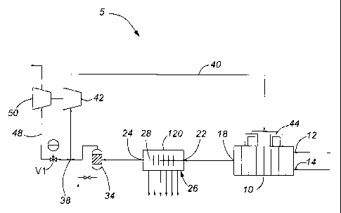
Referring first to Figure 1, a first embodiment of a combustion system 5 of
the invention is
shown in a schematic representation, comprising a system 5 constructed to be
suitable for
connected to any energy conversion system (not shown) which is designed to
receive
thermal energy by contact. In this embodiment, combustion system 5 comprises a
combustor
10, shown as having a plurality of regions, designed for pressurized oxy-
firing, and having
an oxygen inlet 12, a fuel inlet 14, and a combustion products outlet 18, from
which the
stream of flue gas can pass to the inlet 22 of heat exchanger 120, and along
path 28 to the
heat exchanger outlet 24. Heat from the flue gas stream passing through heat
exchanger 120
is received by the energy conversion system from contact surface 26 by any
suitable means
(not shown).
12
SUBSTITUTE SHEET (RULE 26)
CA 02836814 2013-11-20
WO 2012/159189 PCT/CA2011/000593
After passing through heat exchanger 120, the cooler stream of flue gas passes
to condensate
drum 34, which removes any liquid during start-up. The flow path of the flue
gas stream
continues to divider 38, at which recirculation line 40 is separated from
exhaust line 48.
During operation, as discussed further below, the rate of recirculation is
selectively changed
for moderation of the temperature of the combustor, and any residual part of
the flue gas
stream not delivered into recirculation line 40 is passed into the exhaust
stream in line 48,
and through a prime mover, shown here as turbine 50, to be further processed
as a carbon
dioxide product.
The recirculation stream passed into recirculation line 40 is pumped by
circulation pump 42,
and delivered to selected ones of the regions of combustor 10, through
respective ones of the
recirculation inlets 44 provided to combustor 10.
Referring now to Figure 2, a combustion system 205 in a second embodiment of
the
invention is shown, designed for use with a gaseous fuel supply. The
configuration of the
primary components of combustion system 205 is similar to that for combustion
system 5 in
Figure 1. However, the flue gas stream leaving combustor 10 at outlet 18
passes to inlet 222
to pass into and through heat exchanger 220 in a first path 228, while working
fluid from an
energy conversion system (not shown) passes in the opposite direction in a
second path 30
through heat exchanger 220, to receive thermal energy from the flue gas stream
in first path
228. At the same time, if required for load management, as discussed further
below, part of
the flue gas stream leaving combustor 10 at outlet 18 can be diverted around
heat exchanger
220 in optional by-pass line 32, and rejoin the flue gas stream leaving heat
exchanger 220 at
outlet 224.
After divider 38, the recirculation stream is pumped by pump 42 in
recirculation line 40 in
the same manner as shown in Figure 1. However, in this embodiment,
recirculation line 40
is provided with optional heat exchanger 76, which can be used selectively for
removing
part of the thermal energy of the recirculation stream for load management. A
portion of the
13
SUBSTITUTE SHEET (RULE 26)
CA 02836814 2013-11-20
WO 2012/159189 PCT/CA2011/000593
recirculation stream can be separated to join the stream of the oxygen supply
in line 60,
instead of passing directly into the combustor at recirculation inlets 44. For
start-up of this
embodiment, pressurized carbon dioxide is supplied to the combustor through
line 16.
Figure 2 also shows options for the exhaust stream divided from the
recirculation stream at
divider 38. After expansion through a prime mover, shown as turbine 50, the
exhaust stream
optionally can be passed into and through heat exchanger 72, through which the
oxygen
supply also passes, so that excess thermal energy in the exhaust stream can be
used to
partially preheat the oxygen supply. As a further alternative or additional
option, the exhaust
stream can be passed into and through heat exchanger 73, and used to preheat
the gaseous
fuel supply in line 62. Thereafter, the exhaust stream can be passed into
suitable purification
means 52, for the removal of contaminants, before passing into product line
54.
As still further options, excess heat from the energy conversion system can be
used to
contribute to preheating the oxygen supply in line 60 through heat exchanger
74, and to
preheating the gaseous fuel supply in line 62 through heat exchanger 75.
Referring now to Figure 3, a combustion system 305 in a third embodiment of
the invention
is shown in a schematic representation, designed for use with a liquid fuel
supply. This
embodiment is similar in many respects to the embodiment shown in Figure 2 for
a gaseous
supply, including the optional bypass line 32 for load management, the start-
up line 16 for
supply of pressurized carbon dioxide, and heat exchangers 72, 73, 74, 75 and
76. In addition,
part of the recirculation stream in line 40 can be separated to be added to
the supply of liquid
fuel in line 64, to atomize the fuel before delivery into combustor 10 at
input 14;
alternatively or additionally, part of the recirculation stream can be
separated and added to
the oxygen supply in line 60 in the same manner as shown in Figure 2. Further,
to deal with
impurities from the liquid fuel supply, ash removal means, shown here as 36a,
36b and 36c,
can be provided at appropriate locations in the system.
14
SUBSTITUTE SHEET (RULE 26)
CA 02836814 2013-11-20
WO 2012/159189 PCT/CA2011/000593
Referring now to Figure 4, a combustion system 405 in a fourth embodiment of
the
invention is shown in a schematic representation, designed for use with a
solid fuel supply.
In this embodiment, the solid fuel is delivered at feeder 66. Optionally, part
of the
recirculation stream can be separated into line 46 and used to carry the solid
fuel from feeder
66 into inlet 14 of combustor 10. In this embodiment also, optional heat
exchangers 72 and
74 can be used for preheating the oxygen supply in line 60. In the same manner
as shown in
Figure 3, to deal with impurities from the solid fuel supply, ash removal
means, shown here
as 36a, 36b and 36c, can be provided at appropriate locations in the system.
Referring now to Figure 5, a combustion system 505 in a fifth embodiment of
the invention
is shown in a schematic representation, designed for use with a fuel supply in
slurry form. In
this embodiment, the slurry is delivered from feeder 68 directly into
combustor 10 at inlet
14. The features of ash removal means are provided at appropriate locations,
such as at 36a,
36b, 36; and the optional heat exchangers 72, 74 and 76 can be provided in the
same manner
as shown in Figure 4.
Referring now to Figures 2 to 5, the start-up process will consist of the
following steps:
The system can be preheated by closing valves V2, V3 and V5, and partially
opening valves
V1 and V6, and combusting solid, liquid or gaseous fuel with air at ambient
pressure, or
suitable alternative means, to bring it to the operating temperature of the
system, and
running circulation pump 42 using a motor while modulating valves V1 and V6 to
optimize
the rate of heating in different sections of the system. For example, pre-
heating can be
performed by combusting liquid or gaseous fuel with air at ambient pressure.
Suitable
alternative means would include the use of external electrical or solar means,
or other
means. When the preheating is completed, the air and fuel supply are isolated,
and valve V6
is closed.
Following this initial preheating, there are various options for completion of
the start-up.
SUBSTITUTE SHEET (RULE 26)
CA 02836814 2013-11-20
WO 2012/159189 PCT/CA2011/000593
Firstly, for systems to be operated with gaseous fuel, as in Figure 2, the
next steps are as
follows:
1. Pre-pressurize the system with carbon dioxide at a pressure lower than or
equal to the
operating pressure and at a temperature lower than or equal to the operating
temperature of
the system;
2. Start the circulation pump to establish the recirculation stream;
3. Start the flow of fuel and oxygen, initiate combustion, and increase the
flow rates until the
system reaches the normal operating values, while modulating control valve V1
until the
steady state operating pressure and temperature is reached; and
4. While the system is reaching steady state conditions, also modulate control
valves V2 and
V3 to optimize the combustion performance.
As an alternative method for systems to be operated with gaseous fuel, the
next steps can be
as follows:
1. Start the flow of fuel and oxygen and a temperature moderating stream of
pressurized
carbon dioxide from an external source, initiate combustion, and increase the
flow rates until
the system reaches the normal operating values, while modulating control valve
V1 until the
steady state operating pressure and temperature is reached;
2. Concurrently, start the circulation pump and continue circulation to fully
establish the
recirculation stream at steady state conditions, while gradually reducing the
external supply
of pressurized carbon dioxide;
3. While the system is reaching steady state conditions, also modulate control
valves V2 and
V3 to optimize the combustion performance.
Secondly, for systems to be operated with liquid fuel, as in Figure 3, the
next steps are as
follows:
1. Pre-pressurize the system with carbon dioxide at a pressure lower than or
equal to the
operating pressure and at a temperature lower than or equal to the operating
temperature of
the system;
16
SUBSTITUTE SHEET (RULE 26)
CA 02836814 2013-11-20
WO 2012/159189 PCT/CA2011/000593
2. Start the circulation pump to establish the recirculation stream;
3. Start the flow of oxygen and fuel, by atomizing the fuel using a
pressurized carbon
dioxide stream from an external source supplied through control valve V8,
initiate
combustion, and increase the flow rates until the system reaches the normal
operating
values, while modulating control valve V1 until the steady state operating
pressure and
temperature is reached. Concurrently, as the pressure is further built up in
the system,
gradually close valve V8 and open up valve V7; and
4. While the system is reaching steady state conditions, also modulate control
valves V2, V3
and V7 to optimize the combustion performance.
As a further alternative method for systems to be operated with liquid fuel,
the steps can be
as follows:
1. Start the flow of oxygen and fuel and a temperature moderating stream of
pressurized
carbon dioxide from an external source through control valve V8, initiate
combustion, and
increase the flow rates until the system reaches the normal operating values,
while
modulating control valve V1 until the steady state operating pressure and
temperature is
reached. Concurrently, as the pressure is further built up in the system,
gradually close valve
V8 and open up valve V7;
2. Concurrently start the circulation pump and continue circulation to fully
establish the
recirculation stream at steady state conditions, while gradually reducing the
external supply
of pressurized carbon dioxide; and
3. While the system is reaching steady state conditions, also modulate control
valves V2, V3
and V7 to optimize the combustion performance.
During operation, there are various methods of load management of the system,
in response
to the requirements of the energy conversion system to which thermal energy is
supplied
through heat exchanger 220. These methods and options are based on controlling
the amount
of heat being transferred to the energy conversion system through heat
exchanger 220, while
the energy conversion system experiences load variations. The following
options can be
17
SUBSTITUTE SHEET (RULE 26)
CA 02836814 2013-11-20
WO 2012/159189 PCT/CA2011/000593
implemented individually or in combination for gaseous, liquid and solid fuels
(as shown
variously in Figures 2 to 5):
= Introduce a new heat exchanger HX6 to modulate the temperature of the
recirculation stream within the target temperature range.
= Introduce a bypass means around the HX1 with a modulating valve V4 to
control the
flow rate of the bypass stream.
= Introduce an inventory control means through the use of a relief valve V5
to control
the excess pressure, temperature, and mass flow rate within the system.
= Modulate the fuel and 02 flow rates to follow the load variation in the
energy
conversion system.
= Modulate the circulation pump to control the mass flow rate of the
recirculation
stream.
= 18
SUBSTITUTE SHEET (RULE 26)