Note: Descriptions are shown in the official language in which they were submitted.
CA 02836924 2013-11-20
WO 2012/166400 PCT/US2012/038671
- 1 -
WEJ_JAPDRE JUNCTION COMPLETION
WITH FLUID LOSS CONTROL
TECHNICAL FIELD
This disclosure relates generally to equipment utilized
and operations performed in conjunction with a subterranean
well and, in an example described below, more particularly
provides a wellbore junction completion with fluid loss
control.
BACKGROUND
A wellbore junction provides for connectivity in a
branched or multilateral wellbore. Such connectivity can
include sealed fluid communication and/or access between
certain wellbore sections.
Unfortunately, a typical wellbore junction completion
does not provide for fluid loss control. Therefore, it will
be appreciated that improvements would be beneficial in the
art of configuring wellbore junction completions.
CA 02836924 2013-11-20
WO 2012/166400 PCT/US2012/038671
- 2 -
SUMMARY
In the disclosure below, apparatus and methods are
provided which bring improvements to the art of configuring
wellbore junction assemblies. One example is described below
in which a wellbore junction assembly includes a tubular
string which is received in a deflector, and opens a flow
control device. Another example is described below in which
the flow control device isolates sections of a wellbore from
each other, until the tubular string is installed.
In one aspect, the disclosure below describes a method
of installing a wellbore junction assembly in a well. In one
example, the method can include inserting a tubular string
into a deflector, and opening a flow control device in
response to the inserting.
In another aspect, this disclosure provides to the art
a well system. In one example, the well system can include a
deflector positioned at an intersection between at least
three wellbore sections, and a tubular string connector
having at least two tubular strings connected to an end
thereof, one tubular string being received in the deflector
and engaged with a flow control device positioned in a
wellbore section, and another tubular string being received
in another wellbore section.
In yet another aspect, a method of installing a
wellbore junction assembly in a well is described below. In
one example, the method can include inserting a tubular
string into a deflector positioned at a wellbore
intersection, then sealingly engaging the tubular string,
and then opening a flow control device in response to the
inserting.
These and other features, advantages and benefits will
become apparent to one of ordinary skill in the art upon
CA 02836924 2013-11-20
WO 2012/166400 PCT/US2012/038671
- 3 -
careful consideration of the detailed description of
representative examples below and the accompanying drawings,
in which similar elements are indicated in the various
figures using the same reference numbers.
BRIEF DESCRIPTION OF THE DRAWINGS
FIG. 1 is a representative partially cross-sectional
view of a well system and associated method which can embody
principles of this disclosure.
FIG. 2 is a representative partially cross-sectional
view of a wellbore junction assembly which may be used in
the system and method of FIG. 1.
FIG. 3A-E are representative cross-sectional detailed
views of the wellbore junction assembly installed in a
branched wellbore.
FIG. 4 is a representative cross-sectional view of a
portion of the junction assembly including a flow control
device.
FIG. 5 is a representative cross-sectional view of the
junction assembly, with the flow control device being opened
by insertion of a tubular string therein.
FIG. 6 is a representative cross-sectional view of the
junction assembly with another flow control device being
opened therein.
FIGS. 7-10 are representative cross-sectional views of
additional configurations of the flow control device.
DETAILED DESCRIPTION
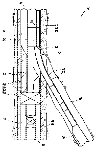
Representatively illustrated in FIG. 1 is a well system
10 and associated method which can embody principles of this
CA 02836924 2013-11-20
WO 2012/166400 PCT/US2012/038671
- 4 -
disclosure. In the well system 10, a wellbore junction 12 is
formed at an intersection of three wellbore sections 14, 16,
18.
In this example, the wellbore sections 14, 16 are part
of a "parent" or main wellbore, and the wellbore section 18
is part of a "lateral" or branch wellbore extending
outwardly from the main wellbore. In other examples, the
wellbore sections 14, 18 could form a main wellbore, and the
wellbore section 16 could be a branch wellbore. In further
examples, more than three wellbore sections could intersect
at the wellbore junction 12, the wellbore sections 16, 18
could both be branches of the wellbore section 14, etc.
Thus, it should be understood that the principles of this
disclosure are not limited at all to the particular
configuration of the well system 10 and wellbore junction 12
depicted in FIG. 1 and described herein.
In one feature of the well system 10, a wellbore
junction assembly 20 is installed in the wellbore sections
14, 16, 18 to provide controlled fluid communication and
access between the wellbore sections. The assembly 20
includes a tubular string connector 22, tubular strings 24,
26 attached to an end 28 of the connector, and a tubular
string 30 attached to an opposite end 32 of the connector.
In this example, the connector 22 provides sealed fluid
communication between the tubular string 30 and each of the
tubular strings 24, 26. In addition, physical access is
provided through the connector 22 between the tubular string
and at least one of the tubular strings 24, 26.
A valve or other flow control device 36 controls flow
30 longitudinally through a tubular string 40 in the wellbore
section 16. In this example, it is desired to maintain the
flow control device 36 closed until the junction assembly 20
CA 02836924 2013-11-20
WO 2012/166400
PCT/US2012/038671
- 5 -
is installed at the wellbore junction 12, in order to
prevent loss of fluid into an earth formation penetrated by
the wellbore, to prevent fluid from flowing to the surface
from the formation below the valve (e.g., to prevent a
"kick" or fluid influx) and/or to prevent pressure above the
valve from being applied to the formation below the valve,
etc.
In the example depicted in FIG. 1, the wellbore
sections 14, 16 are lined with casing 42 and cement 44, but
the wellbore section 18 is uncased or open hole. A window 46
is formed through the casing 42 and cement 44, with the
wellbore section 18 extending outwardly from the window.
However, other completion methods and configurations
may be used, if desired. For example, the wellbore section
18 could be lined, with a liner therein being sealingly
connected to the window 46 or other portion of the casing
42, etc. Thus, it will be appreciated that the scope of this
disclosure is not limited to any of the features of the well
system 10 or the associated method described herein or
depicted in the drawings.
A deflector 48 is secured in the casing 42 at the
junction 12 by a packer, latch or other anchor 50. The
tubular string 40 is sealingly secured to the anchor 50 and
deflector 48, so that a passage 52 in the tubular string 40
is in communication with a passage 54 in the deflector 48
when the flow control device 36 is open. The flow control
device 36 may be closed, for example, after setting the
packer 50 in the wellbore portion 16. The tubular string 24
is thereafter engaged with seals 56 in the deflector 48, so
that the tubular string 24 is in sealed communication with
the tubular string 40 in the wellbore section 16.
CA 02836924 2013-11-20
WO 2012/166400 PCT/US2012/038671
- 6 -
A bull nose 58 on a lower end of the tubular string 26
is too large to fit into the passage 54 in the deflector 48
and so, when the junction assembly 20 is lowered into the
well, the bull nose 58 is deflected laterally into the
wellbore section 18. The tubular string 24, however, is able
to fit into the passage 54 and, when the junction assembly
20 is appropriately positioned as depicted in FIG. 1, and
the flow control device 36 is opened, the tubular string 24
will be in sealed communication with the tubular string 40
via the passage 52.
In the example of FIG. 1, fluids (such as hydrocarbon
fluids, oil, gas, water, steam, etc.) can be produced from
the wellbore sections 16, 18 via the respective tubular
strings 24, 26. The fluids can flow via the connector 22
into the tubular string 30 for eventual production to the
surface.
However, such production is not necessary in keeping
with the scope of this disclosure. In other examples, fluid
(such as steam, liquid water, gas, etc.) could be injected
into one of the wellbore sections 16, 18 and another fluid
(such as oil and/or gas, etc.) could be produced from the
other wellbore section, fluids could be injected into both
of the wellbore sections 16, 18, etc. Thus, any type of
injection and/or production operations can be performed in
keeping with the principles of this disclosure.
Referring additionally now to FIG. 2, a partially
cross-sectional view of the wellbore junction assembly 20 is
representatively illustrated, apart from the remainder of
the system 10. In this example, a fluid 60 is produced from
the wellbore section 16 via the tubular string 24 to the
connector 22, and another fluid 62 is produced from the
wellbore section 18 via the tubular string 26 to the
CA 02836924 2013-11-20
WO 2012/166400 PCT/US2012/038671
- 7 -
connector. The fluids 60, 62 may be the same type of fluid
(e.g., oil, gas, steam, water, etc.), or they may be
different types of fluids.
The fluid 62 flows via the connector 22 into another
tubular string 64 positioned within the tubular string 30.
The fluid 60 flows via the connector 22 into a space 65
formed radially between the tubular strings 30, 64.
Chokes or other types of flow control devices 66, 68
can be used to variably regulate the flows of the fluids 60,
62 into the tubular string 30 above the tubular string 64.
The devices 66, 68 may be remotely controllable by direct,
wired or wireless means (e.g., by acoustic, pressure pulse
or electromagnetic telemetry, by optical waveguide,
electrical conductor or control lines, mechanically,
hydraulically, etc.), allowing for an intelligent completion
in which production from the various wellbore sections can
be independently controlled.
Although the fluids 60, 62 are depicted in FIG. 2 as
being commingled in the tubular string 30 above the tubular
string 64, it will be appreciated that the fluids could
remain segregated in other examples. In addition, although
the device 68 is illustrated as possibly obstructing a
passage 70 through the tubular string 64, in other examples
the device 68 could be positioned so that it effectively
regulates flow of the fluid 62 without obstructing the
passage.
Referring additionally now to FIGS. 3A-E, detailed
cross-sectional views of the junction assembly 20 as
installed in the wellbore sections 14, 16, 18 of the well
system 10 are representatively illustrated. For clarity, the
remainder of the well system 10 is not illustrated in FIGS.
3A-E.
CA 02836924 2013-11-20
WO 2012/166400 PCT/US2012/038671
- 8 -
In FIGS. 3A-E, it may be clearly seen how the features
of the junction assembly 20 cooperate to provide for a
convenient and effective installation in the wellbore
sections 14, 16, 18. Note that the tubular string 26 has
been deflected by the deflector 48 into the wellbore section
18, the tubular string 24 is sealingly received in the seals
56, and the flow control device 36 has been opened in
response to inserting the tubular string 24 into the
passages 52, 54. Fluid communication is now established
between the connector 22 (and the tubular string 30
thereabove) and each of the tubular strings 24, 26.
Preferably, the tubular string 24 is sealingly engaged
with the seals 56 prior to the flow control device 36 being
opened. In this manner, sealed fluid communication is
established between the tubular string 24 and the passage 54
prior to opening the flow control device 36, thereby
enhancing continued control over pressure and flow
communicated to the passage 52 (and formations penetrated
below the wellbore section 16) when the flow control device
is opened.
The flow control device 36 may be opened using a
variety of different techniques, some of which are described
below. However, the scope of this disclosure is not limited
to the particular techniques for opening the various
examples of the flow control device 36 described below,
since any method of opening the flow control device may be
used in keeping with the scope of this disclosure.
Preferably, the flow control device 36 opens in
response to the tubular string 24 being inserted into the
passages 52, 54. As mentioned above, the flow control device
36 is also preferably opened after the tubular string 24 is
sealingly engaged with the seals 56.
CA 02836924 2013-11-20
WO 2012/166400 PCT/US2012/038671
- 9 -
Referring additionally now to FIG. 4, an enlarged scale
cross-sectional view of a section of the junction assembly
20 is representatively illustrated apart from the remainder
of the well system 10. In this example, the flow control
device 36 is positioned just below the seals 56, so that,
when the tubular string 24 is inserted into the passage 54,
the tubular string will engage the seals 56 just prior to
engaging the flow control device.
The flow control device 36 is similar in some respects
to a Glass Disc Sub (Model DP-SDS) marketed by Halliburton
Energy Services, Inc. of Houston, Texas USA. The flow
control device 36 includes a frangible barrier 72 (such as
glass or ceramic, etc.) which initially prevents fluid
communication between the passages 52, 54. When the barrier
72 is broken, fluid communication is permitted between the
passages 52, 54.
At least two ways of breaking the barrier 72 are
provided. The tubular string 24 can break the barrier 72
when the tubular string is inserted into the passage 54 (as
depicted in FIG. 5), or increased pressure in the passage 52
below the flow control device 36 can displace an annular
piston 74 to impact the barrier from below.
Increased pressure in the passage 52 below the flow
control device 36 could be due to stinging the deflector 48
into the anchor 50. In that case, the barrier 72 could be
broken due to the increased pressure, prior to inserting the
tubular string 24 into the passage 54.
In another example, the device 36 could be operated by
applying pressure to a control line or port in communication
with a chamber (not shown) exposed to a piston (see FIG. 4)
of the device. The piston would then displace when pressure
in the chamber is increased sufficiently to break shear
CA 02836924 2013-11-20
WO 2012/166400
PCT/US2012/038671
- 10 -
pins/screws, or another type of releasing device, in order
to break the barrier 72.
In yet another example, the device 36 could be turned
upside-down, so that the piston of the device is exposed to
pressure in the passage 54 above the barrier 72. In this
example, increased pressure applied to the passage 54 will
cause the piston to displace, in order to break the barrier
72.
In a further example, pressure applied to the tubular
string 24 can be used to apply pressure to the passage 54
(or to another passage, such as a passage extending through
a sidewall of the deflector 48, etc.), in order to displace
the piston of the device 36 and break the barrier 72.
Referring additionally now to FIG. 6, another
configuration of the junction assembly 20 is
representatively illustrated. In this configuration, the
barrier 72 is pierced by the tubular string 24 when it is
inserted into the passage 52.
The barrier 72 in this example is preferably a
severable metal disc, similar to that used in an ANVIL(TM)
plugging system marketed by Halliburton Energy Services,
Inc. The barrier 72 is preferably cut by a lower end of the
tubular string 24, and folded out of the way, so that the
tubular string can extend through it into the passage 52.
Referring additionally now to FIG. 7, another example
of the flow control device 36 is representatively
illustrated, apart from the remainder of the junction
assembly 20. In this example, the barrier 72 is generally
hemispherical in shape, and is preferably made of a ceramic
material, so that the barrier is frangible.
CA 02836924 2013-11-20
WO 2012/166400 PCT/US2012/038671
- 11 -
The curved shape of the barrier 72 enables it to
withstand a substantial pressure differential from the
passage 54 to the passage 52. In addition, the barrier 72
can be readily broken by the tubular string 24 when it is
inserted into the passages 52, 54.
Referring additionally now to FIG. 8, a portion of
another configuration of the flow control device 36 is
representatively illustrated. In this configuration, two
oppositely facing barriers 72 are used, so that the barriers
can withstand substantial pressure differentials from both
longitudinal directions (e.g., from the passage 52 to the
passage 54, and from the passage 54 to the passage 52).
The barriers 72 in the FIGS. 7 & 8 configurations may
be similar to the MAGNUMDISK(TM) marketed by Magnum Oil
Tools of Corpus Christi, Texas USA. In the FIG. 8
configuration, a pressure equalizing device 76 may be used
to prevent trapping atmospheric pressure between the
barriers 72. The device 76 equalizes pressure in the space
between the barriers 72 with the passage 52 or 54 having the
greatest pressure at any given time.
Referring additionally now to FIG. 9, another example
of the flow control device 36 is representatively
illustrated. In this example, the flow control device 36
comprises a ball valve, with the barrier 72 being a
rotatable ball which selectively permits and prevents fluid
communication between the passages 52, 54.
An actuation sleeve 78 of the flow control device 36
has a latch profile 80 formed therein. Collets or keys (not
shown) on the lower end of the tubular string 24 can engage
the profile 80 and shift the sleeve 78 downward to open the
barrier 72 and permit fluid communication between the
passages 52, 54. The barrier 72 can be closed by shifting
CA 02836924 2013-11-20
WO 2012/166400 PCT/US2012/038671
- 12 -
the sleeve 78 upward, for example, by withdrawing the
tubular string 24 (or another tool, such as a shifting tool,
etc.) from the passage 54.
The flow control device 36 of FIG. 9 may be similar to
a Model IB isolation valve marketed by Halliburton Energy
Services, Inc. Other types of flow control devices which may
be used include (but are not limited to) flapper valves,
dissolvable plugs (such as the MIRAGE(TM) plug marketed by
Halliburton Energy Services, Inc.), swellable materials,
etc. Any type of flow control device may be used, in keeping
with the scope of this disclosure.
Referring additionally now to FIG. 10, another
configuration of the flow control device 36 is
representatively illustrated. This configuration is similar
in some respects to the configuration of FIGS. 4 & 5.
The FIG. 10 flow control device 36 can be actuated to
open the barrier 72 by application of increased pressure to
the passage 54 above the barrier. When the pressure in the
passage 54 has been increased to a predetermined level, the
piston 74 will displace to pierce the barrier 72 and cause
it to disperse, dissolve, disintegrate or otherwise degrade.
The barrier 72 can also be pierced by the tubular string 24.
Note that, in the various examples described above, the
flow control device 36 is not necessarily positioned just
below the seals 56, but could be positioned elsewhere, if
desired. For example, the flow control device 36 could be
positioned above the seals 56, in a latch mechanism of the
deflector 48, etc.
The tubular string 24 could include a latch or other
device to engage and operate the flow control device 36.
Alternatively, the latch or other device could be separately
CA 02836924 2013-11-20
WO 2012/166400 PCT/US2012/038671
- 13 -
conveyed through the tubular string 24 to the flow control
device 36 to open the flow control device.
It may now be fully appreciated that this disclosure
provides significant improvements to the art of constructing
wellbore junctions. The tubular string 24 can be inserted
through the deflector 48 to open the flow control device 36
and thereby provide fluid communication between the passage
52 below the flow control device and the interior of the
wellbore junction assembly 20.
The above disclosure describes a method of installing a
wellbore junction assembly 20 in a well. In one example, the
method can include inserting a first tubular string 24
through a deflector 48, and opening a flow control device 36
in response to the inserting.
The method may also include sealingly engaging the
first tubular string 24 after inserting the first tubular
string 24 into the deflector 48 and prior to opening the
flow control device 36.
Opening the flow control device 36 may include breaking
a frangible barrier 72, cutting through a barrier 72, and/or
rotating a barrier 72.
The method can include deflecting a second tubular
string 26 laterally off of the deflector 48. One end 28 of a
tubular string connector 22 may be connected to the first
and second tubular strings 24, 26.
A well system 10 is also described above. In one
example, the well system 10 can include a deflector 48
positioned at an intersection between first, second and
third wellbore sections 14, 16, 18, and a tubular string
connector 22 having first and second tubular strings 24, 26
connected to an end 28 thereof. The first tubular string 24
CA 02836924 2013-11-20
WO 2012/166400 PCT/US2012/038671
- 14 -
is received in the deflector 48 and engaged with a flow
control device 36 positioned in the first wellbore section
16, and the second tubular string 26 being received in the
second wellbore section 18.
The first tubular string 24 may extend through the flow
control device 36. The flow control device 36 may open in
response to insertion of the first tubular string 24
therein.
The well system 10 can also include at least one seal
56 which sealingly engages the first tubular string 24.
The flow control device 36 may comprise a frangible
barrier 72. The flow control device 36 may comprise a
barrier 72 which opens in response to insertion of the first
tubular string 24 through the deflector 48.
The flow control device 36 may operate in response to
pressure in the first tubular string 24.
A method of installing a wellbore junction assembly 20
in a well is also described above. In one example, the
method can include inserting a first tubular string 24 into
a deflector 48 positioned at a wellbore intersection, then
sealingly engaging the first tubular string 24, and then
opening a flow control device 36 in response to the
inserting.
The sealingly engaging step may include providing
sealed fluid communication between the tubular string 24 and
a flow passage 54 extending through the deflector 48.
It is to be understood that the various examples
described above may be utilized in various orientations,
such as inclined, inverted, horizontal, vertical, etc., and
in various configurations, without departing from the
principles of this disclosure. The embodiments illustrated
CA 02836924 2013-11-20
WO 2012/166400 PCT/US2012/038671
- 15 -
in the drawings are depicted and described merely as
examples of useful applications of the principles of the
disclosure, which are not limited to any specific details of
these embodiments.
In the above description of the representative
examples, directional terms (such as "above," "top,"
"below," "bottom," "upper," "lower," etc.) are used for
convenience in referring to the accompanying drawings. In
general, "above," "upper," "upward" and similar terms refer
to a direction toward the earth's surface along a wellbore,
and "below," "lower," "downward" and similar terms refer to
a direction away from the earth's surface along the
wellbore, whether the wellbore is horizontal, vertical,
inclined, deviated, etc. However, it should be clearly
understood that the scope of this disclosure is not limited
to any particular directions described herein.
Of course, a person skilled in the art would, upon a
careful consideration of the above description of
representative embodiments, readily appreciate that many
modifications, additions, substitutions, deletions, and
other changes may be made to these specific embodiments, and
such changes are within the scope of the principles of this
disclosure. Accordingly, the foregoing detailed description
is to be clearly understood as being given by way of
illustration and example only, the spirit and scope of the
invention being limited solely by the appended claims and
their equivalents.