Note: Descriptions are shown in the official language in which they were submitted.
CA 02836941 2013-12-17
54106-450D1
BINDING METHODS AND DEVICES IN A
BUILDING AUTOMATION SYSTEM
This application is a divisional application of application serial No. 2662014
filed August 29, 2007 as a PCT International application.
BACKGROUND
[0001J The present disclosure generally relates to building automation
systems.
In particular, the present disclosure relates to methods and devices for
manually
binding or linking automation components within a building automation system.
[0002] A building automations system (BAS) typically integrates and
controls
elements and services within a structure such as the heating, ventilation and
air
conditioning (HVAC) system, security services, fire systems and the like. The
integrated and controlled systems are arranged and organized into one or more
floor
level networks (FLNs) containing application or process specific controllers,
sensors,
actuators, or other devices distributed or wired to form a network. The floor
level
networks provide general control for a particular floor or region of the
structure. For
1
CA 02836941 2013-12-17
54106-450D1
example, a floor level network may be an RS-485 compatible network that
includes
one or more controllers or application specific controllers configured to
control the
elements or services within floor or region. The controllers may, in turn, be
configured to receive an input from a sensor or other device such as, for
example, a
temperature sensor (RTS) deployed to monitor the floor or region. The input,
reading or signal provided to the controller, in this example, may be a
temperature
indication representative of the physical temperature. The temperature
indication
can be utilized by a process control routine such as a proportional-integral
control
routine executed by the controller to drive or adjust a damper, heating
element,
cooling element or other actuator towards a predefined set-point.
[0003] Information such as the temperature indication, sensor readings
and/or
actuator positions provided to one or more controllers operating within a
given floor
level network may, in tum, be communicated to an automation level network
(ALN)
or building level network (BLN) configured to, for example, execute control
applications, routines or loops, coordinate time-based activity schedules,
monitor
priority based overrides or alarms and provide field level information to
technicians.
Building level networks and the included floor level networks may, in tum, be
integrated into an optional management level network (MLN) that provides a
system
for distributed access and processing to allow for remote supervision, remote
control,
statistical analysis and other higher level functionality. Examples and
additional
information related to BAS configuration and organization may be fOund in the
co-
pending U.S. patent application serial No. 11/590,157 (2006P18573 US), filed
on
October 31, 2006, and co-pending U.S. patent application serial No. 10/915,034
2
CA 02836941 2013-12-17
54106-450D1
(2004P13093 US), filed on August 8, 2004.
[0004] Wireless devices, such as devices that comply with IEEE
802.15.4/ZigBee
protocols, may be implemented within the control scheme of a building
automation
system without incurring additional wiring or installation costs. ZigBee-
compliant
devices such as full function devices (FFD) and reduced function devices (RFD)
may
be interconnected to provide a device net or mesh within the building
automation
system. For example, full function devices are designed with the processing
power
necessary to establish peer-to-peer connections with other full function
devices
and/or execute control routines specific to a floor or region of a floor level
network.
Each of the full function devices may, in turn, communicate with one or more
of the
reduced function devices in a hub and spoke arrangement. Reduced function
devices such as the temperature sensor described above are designed with
limited
processing power necessary to perform a specific task(s) and communicate
information directly to the connected full function device.
[0005] Wireless devices for use within the building automation system
must be
configured in order to establish communications with the different elements,
components and networks that comprise the building automation system. Systems
and method for configuring and establishing communications between the
wireless
devices and the automation components may be desirable and facilitate the
setup,
configuration, maintenance and operation of ,the building automation system.
3
CA 02836941 2013-12-17
54106-450D1
SUMMARY
[00061 The present disclosure generally provides for manually binding wireless
devices and/or automation components operating within a building automation
system (BAS). Wireless devices and/or automation components need to be bound,
linked or otherwise joined in order to communicate with each other. Generally
the
disclosed devices and methods are configured to wirelessly communicate
information, identifiers and requests configured to establish binding
relationships
there between.
[0007] In one embodiment, an automation component configured for wireless
communication within a building automation system is disclosed. The automation
component includes a communication module having a communication port, and a
=
wireless communication component. The automation component further includes a
processor in communication with the communication module, a memory in
communication with the processor, the memory configured to store computer
readable instructions which are executable by the processor. The computer
readable instructions are programmed to receive a component identifier via the
communications port, generate a binding request based on the received
component
identifier, and communicate the binding request via the wireless communication
component.
[0008] In another embodiment, a method for binding an automation component
within a building automation system is disclosed. The method includes
receiving a
component identifier via a communication port, generating a binding request
based
on the received component identifier, and communicating the binding request
via a
4
CA 02836941 2013-12-17
54106-450D1
wireless communication component, wherein the binding request is addressed to
the
received component identifier.
[0009] In another embodiment, an automation component configured for wireless
communication within structure having a.building automation system is
disclosed.
The automation component includes a wireless communications component, a
processor in communication with the wireless communications component, a
memory in communication with the processor, the memory configured to store
computer readable instructions which are executable by the processor. The
computer readable instructions are programmed to receive a location signal,
receive
a signal strength indicator, and determine a position within the structure as
a function
of the location signal and the signal strength indicator.
[0010] .In another embodiment, an automation component configured for wireless
communication within structure having a building automation system is
disclosed.
The automation component includes a wireless communication component, a
location communication component in communication with the wireless
=
communication component, wherein the location component is configured to
provide
a location signal, and a signal strength indication component in communication
with
the wireless communication component, wherein the location component is
configured to provide a signal strength indicator.
[0011] In another embodiment, a method for binding an automation
component
within a building automation system is disclosed. The method includes
receiving a
location signal communicated by a location communication component, receiving
a
signal strength indicator communicated by the location communitation
component,
CA 02836941 2015-05-01
54106-450D1
determining a position as a function of the location signal and the signal
strength
indicator, and communicating a binding request to a second automation
component
within a communication range associated with the position.
[0012] According to one aspect of the present invention, there is
provided an
automation component configured for wireless communication within a structure
having a building automation system, the automation component comprising: a
wireless communication component; a processor in communication with the
wireless
communication component; and a memory in communication with the processor, the
memory configured to store computer readable instructions which are executable
by
the processor; wherein the computer readable instructions are programmed to:
receive a location signal; receive a signal strength indicator; determine a
position
within the structure as a function of the location signal and the signal
strength
indicator; based on the position, identify another automation component within
a
communication range without communicating with the other automation component;
communicate a binding request to the other automation component, wherein the
binding request includes a handshake query associated with the other
automation
component; and establish, in response to the handshake query, a direct
communication link to the other automation component.
[0012A] According to another aspect of the present invention, there is
provided
an automation component configured for wireless communication within structure
having a building automation system, the automation component comprising: a
wireless communication component; a location communication component in
communication with the wireless communication component, wherein the location
communication component is configured to provide a location signal; a signal
strength indication component in communication with the wireless communication
component, wherein the location communication component is configured to
provide
a signal strength indicator; wherein the wireless communication component is
configured to communicate a binding request including a handshake query to
another
automation component within a communication range of the location
communication
component, the other automation component being identifiable as within a
6
CA 02836941 2014-09-24
54106-450D1
communication range without communicating with the other automation component;
and wherein the wireless communication component is configured to establish a
direct communication link to the other automation component in response to a
reply
received in connection with the handshake query.
[0012B] According to a further aspect of the present invention, there is
provided
a method for binding an automation component within a building automation
system,
the method comprising: receiving a location signal communicated by a location
communication component; receiving a signal strength indicator communicated by
the location communication component; determining a position as a function of
the
location signal and the signal strength indicator; communicating a binding
request
including a handshake query to another automation component within a
communication range associated with the position, the other automation
component
being identifiable as within the communication range without communicating
with the
other automation component; and establishing, upon receipt of a handshake
response to the handshake query, a direct communication link to the other
automation component.
[0013] Additional features and advantages of the present invention are
described in, and will be apparent from, the following Detailed Description
and the
figures.
BRIEF DESCRIPTION OF THE FIGURES
[0014] The method, system and teaching provided relate to binding
automation
components within a building automation system (BAS).
[0015] FIG. 1 illustrates an embodiment of a building automation
system
configured in accordance with the disclosure provided herein;
[0016] FIG. 2 illustrates an embodiment of a wireless device or automation
component that may be utilized in connection with the building automation
system
shown in FIG. 1;
6a
CA 02836941 2014-09-24
54106-450D1
[0017] FIG. 3 illustrates an exemplary flowchart representative of an
exemplary
binding operation;
[0018] FIGS. 4A and 4B illustrate an exemplary binding operation that
may be
implemented in connection with the building automation system shown in FIG. 1;
[0019] FIGS. 5A and 5B illustrate another exemplary binding operation that
may be implemented in connection with the building automation system shown in
FIG. 1;
[0020] FIG. 6 illustrates another exemplary binding operation that may
be
implemented in connection with the building automation system shown in FIG. 1;
and
6b
CA 02836941 2013-12-17
54106-450D1
[0021] FIG. 7 illustrates an exemplary location based binding operation
that may
be implemented in connection with the building automation system shown in FIG.
1.
DETAILED DESCRIPTION
[0022] The embodiments discussed herein include automation components,
wireless devices and transceivers. The devices may be IEEE 802.15.4/ ZigBee-
compliant automation components such as: a personal area network (PAN)
coordinator which may be implemented as a field panel transceivers (FPX); a
full
function device (FFD) implemented as a floor level device transceiver (FLNX);
and a
reduced function device (RFD) implemented as a wireless room temperature
sensor
(WRTS) that may be utilized in a building automation system (BAS). The devices
identified herein are provided as an example of automation components,
wireless
devices and transceivers that may be integrated and utilized within a building
automation system embodying the teachings disclosed herein and are not
intended
to limit the type, functionality and interoperability of the devices and
teaching
discussed and claimed herein.
l. BUILDING AUTOMATION SYSTEM OVERVIEW
[0023] One exemplary building automation system that may include the
devices
and be configured as described above is the APOGEE system provided by
Siemens Building Technologies, Inc. The APOGEE system may implement RS-
485 wired communications, Ethernet, proprietary and standard protocols, as
well as
known wireless communications standards such as, for example, IEEE 802.15.4
wireless communications which are compliant with the ZigBee standards and/or
ZigBee certified wireless devices or automation components. ZigBee standards,
proprietary protocols or other standards are typically implemented in embedded
7
CA 02836941 2013-12-17
54106-450D1
=
applications that may utilize low data rates and/or require low power
consumption.
Moreover, ZigBee standards and protocols are suitable for establishing
inexpensive,
self-organizing, mesh networks which may be utilized for industrial control
and
sensing applications such as building automation. Thus, automation components
configured in compliance with ZigBee standards or protocols may require
limited
amounts of power allowing individual wireless devices, to operate for extended
periods of time on a finite battery charge.
[0024] The wired or wireless devices such as the IEEE 802.15.4/ZigBee-
compliant automation components may include, for example, an RS-232 standard
compliant port with an RJ11 or other type of connector, an RJ45 Ethernet
compatible
port, and/or a universal serial bus (USB) connection. These wired, wireless
devices
or automation components may, in tum, be configured to include or interface
with a
separate wireless transceiver or other communications peripheral thereby
allowing
the wired device to communicate with the building automation system via the
above-
described wireless protocols or standards. Alternatively, the separate
wireless
transceiver may be coupled to a wireless device such as a IEEE 802.15.4/
ZigBee-
compliant automation component to allow for communications via a second
communications protocol such as, for example, 802.11x protocols (802.11a,
802.11b
... 802.11n, etc.) These exemplary wired, wireless devices may further include
a
man-machine interface (MMI) such as a web-based interface screen that provide
access to configurable properties of the device and allow the user to
establish or
troubleshoot communications between other devices and elements of the BAS.
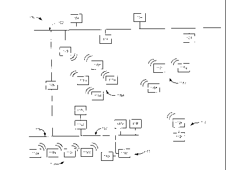
[0025] FIG. 1 illustrates an exemplary building automation system or
control
system 100 that may incorporate the methods, systems and teaching provided
8
CA 02836941 2013-12-17
54106-450D1
herein. The control system 100 includes a first network 102 such as an
automation
level network (ALN) or management level network (MLN) in communication with
one
or more controllers such as a plurality of terminals 104 and a modular
equipment
controller (MEC) 106. The modular equipment controller or controller 106 is a
programmable device which may couple the first network 102 to a second network
108 such as a floor level network (FLN). The second network 108, in this
exemplary
embodiment, may include a wired network 122 that connects to building
automation
components 110 (individually identified as automation components 110a to
110f).
The second network 108 may further be coupled to wireless building automation
components 112. For example, the building automation components 112 may
include wireless devices individually identified as automation components 112a
to
112f. In one embodiment, the automation component 112f may be a wired device
that may or may not include wireless functionality and connects to the
automation
component 112e. In this configuration, the automation component 1121 may
utilize
or share the wireless functionality provided by the automation component 112e
to
define an interconnected wireless node 114.
[0026] The control system 100 may further include automation components
generally identified by the reference numerals 116a to 116g. The automation
components 116a to 116g may be configured or arranged to establish one or more
networks or subnets 118a and 118b. The automation components 116a to 116g
such as, for example, full or reduced function devices and/or a configurable
terminal
equipment controller (TEC), cooperate to wirelessly communicate information
between the second network 108, the control system 100 and other devices
within
the mesh networks or subnets 118a and 118b. For example, the automation
9
CA 02836941 2013-12-17
54106-450D1
component 116a may communicate with other automation components 116b to 116d
within the mesh network 118a by sending a message addressed to the network OR
component identifier, alias and/or media access control (MAC) address assigned
to
each of the interconnected automation components 116a to 116g and/or to a
field
panel 120. In one configuration, the individual automation components 116a to
116d
within the subnet 118a may communicate directly with the field panel 120 or,
alternatively, the individual automation components 116a to 116d may be
configured
in a hierarchal manner such that only one of the components for example,
automation component 116c, communicates with the field panel 120. The
automation components 116e to 116g of the mesh network 118b may, in turn,
communicate with the individual automation components 116a to 116d of the mesh
network 118a or the field panel 120.
[0027] The automation components 112e and 112f defining the wireless node
114 may wirelessly communicate with the second network 108, and the automation
components 116e to 116g of the mesh network 118b to facilitate communications
between different elements, section and networks within the control system
100.
Wireless communication between individual the automation components 112, 116
and/or the subnets 118a, 118b may be conducted in a direct or point-to-point
manner, or in an indirect or routed manner through the nodes or devices
comprising
the nodes or networks 102, 108, 114 and 118. In an alternate embodiment, the
wired network 122 is not provided, and further wireless connections may be
utilized.
[0028] FIG. 2 illustrates an exemplary automation component 200 that may
be
utilized within the control system 100. The automation component 200 maybe be
a
full function device or a reduced function device and may be utilized
interchangeably
CA 02836941 2013-12-17
54106-450D1
with the automation components 110, 112 and 116 shown and discussed in
connection with FIG. 1. The automation component 200 in this exemplary
embodiment may include a processor 202 such as an INTEL PENTIUM class
processor in communication with a memory 204 or storage medium. The memory
204 or storage medium may contain random access memory (RAM) 206, flashable
or non-flashable read only memory (ROM) 208 and/or a hard disk drive (not
shown),
or any other known or contemplated storage device or mechanism. The automation
component may further include a communications module 210. The
communications module 210 may include, for example, the ports, hardware and
software necessary to implement wired communications with the control system
100.
The communications module 210 may alternatively, or in addition to, contain a
wireless transmitter 212 and a receiver 214 communicatively coupled to an
antenna
216 or other broadcast hardware.
[0029] The
communication module 210 may further include a communication port
220. The communication port 220 may be an infrared (IR) port configured to
communicate, e.g., transmit and/or receive, information. For example, many
known
personal digital assistants (PDAs) include IR ports for communications and may
be
configured to store and communicate component identifiers such as, for
example,
MAC addresses, via the IR port. In another embodiment, communication port 220
may be a serial port compliant with, for example, RS-232 and/or RS-422
standards
and may utilize, for example, a 25-pin D-type connector. In this example, the
serial port may cooperate with a serial cable (not shown) to exchange or
communicate information between the automation component 200 and another
11
CA 02836941 2013-12-17
54106-450D1
automation component 110, 112 and 116. Altematively, the serial cable may be
a "smart" cable that includes a controller (not shown) having a processor
and/or a
memory. The smart cable may be configured to initiate communications between
the automation component 200 and another automation component 110, 112 and
116 in order to exchange component identifiers.
[0030] The sub-components 202, 204 and 210 of the exemplary automation
component 200 may be coupled and able to share information with each other via
a
communications bus 218. In this way, computer readable instructions or code
such
as software or firmware may be stored on the memory 204. The processor 202 may
read and execute the computer readable instructions or code via the
communications bus 218. The resulting commands, requests and queries may be
provided to the communications module 210 for transmission via the transmitter
212
and the antenna 216 to other automation components 200, 112 and 116 operating
within the first and second networks 102 and 108.
II. AUTOMATION COMPONENT BINDING
[0031] FIG. 3 illustrates an overview of a wireless binding operation or
procedure
300 that may be implemented between one or more of the exemplary automation
components 200 (see FIG. 2), the automation components 110, 112 and 116 (see
FIG. 1) and/or a terrninal equipment controller (TEC), other full function
devices, a
workstation 104, etc. within the control system 100. The binding operation may
be
utilized to augment binding operations in which devices within the control
system 100
are physically connected or wired together to define the networks 102, 108 and
subnets 118a, 118b of the control system 100. Binding as used herein describes
the
12
CA 02836941 2013-12-17
54106-450D1
=
logical and communications relationship utilized to join or link devices,
components
and elements within the control system 100.
[0032] At block 302, one or more of the automation components, for
example, the
automation components 200, 112 and 116, to be bound together or with other
components, elements or subsystems of the control system 100 may be physically
setup or emplaced within the structure. While all of the automation components
200,
112 and 116 may be utilized interchangeably with the teachings disclosed
herein, the
automation component 200 will be referred to herein for convenience and
clarity.
The physical setup may include mounting or otherwise positioning the
automation
component 200 within a given region or area or a structure to be monitored.
For
example, if the automation component 200 is a wireless room temperature sensor
(WRTS), it may be positioned within an area of the structure in which the
temperature is to be monitored.
[0033] The physical setup may further include positioning or mounting the
automation component 200 within a specific distance or range of another
automation
component 200 and/or other full function or reduced function devices operating
within the control system 100. For example, in order to establish the subnet
118b,
the automation component 200 may be positioned within two hundred feet (200ft)
or
approximately sixty meters (60m) of another component or device. The physical
setup may further include: ensuring broadcast or line-of-site communications
around
the mounting position for the automation component 200, checking or monitoring
the
power source of the automation component 200, e.g., verifying the fuel cell,
battery,
13
CA 02836941 2013-12-17
54106-450D1
line power, magnetic resonance receiver, measuring or recording the
communication
or broadcast signal strengths or power within the area, etc.
=
[0034] In another embodiment, the physical setup can include creating a
map or
diagram of the automation components 200, 110, 112 and 116 disposed and
secured throughout the structure controlled and monitored by the control
system
100. The map may include the physical location, device type, configuration and
communication or broadcast signal strength or power of the automation
component
200, 110, 112 and 116 within the area of the structure to be monitored.
[0035] At block 304, the basic configuration, logical setup or
commissioning of the
automation component 200 may be established. The basic configuration may
include assigning a component identifier, a network name or alias, a media
access
control (MAC) address, a network or subnet password, etc. In one embodiment,
the
automation component 200 may be configured with a list or database of
information
detailing the component's communication schedule, other devices or components
in
the control system 100 to which communications should be established,
communications or information priorities, etc. The basic configuration may be
accomplished by way of a direct, e.g., wired, infrared, etc., connection
between a
portable device 400 (see FIG. 4) such as a laptop, a personal digital
assistant, a
universal remote control, a barcode reader or scanner, etc. Alternatively,
each
automation component 200 may be assigned a unique component identifier or
identification such as a hexadecimal code or string. For example, if the
portable
device 400 is a universal remote control, a numeric or hexadecimal number
representing the component identifier may be communicated to the automation
14
CA 02836941 2013-12-17
54106-450D1
component 200 via either a wireless connection such as a radiofrequency (RF)
connection and/or an infrared (IR) connection. The assigned component
identifier,
allows the portable device 400 and/or another automation component 110, 112
and
116 to communicate with the automation component 200.
[0036] At block 306, the portable device 400 may further be utilized in
cooperation with the now-configured automation component 200 to initiate a
binding
sequence between the component and one or more devices operating within the
control system 100 utilizing the component identifier. For example, the
portable
device 400 may be a laptop computer having a communications program such as,
for example, WINDOWS HyperTerminal or other man machine interface (MMI),
into which a bind initiate command may be entered and provided to the
automation
component 200. The bind initiate command may include the component identifier,
identification and/or alias of, for example, the terminal equipment
controller, full
function device or network, to which the automation component 200 is to be
bound.
[0037] In another embodiment, the communication port 220 of the
automation
component 200 may be an infrared port configured for communications with the
portable device 400 discussed above. In particular, the infrared port 220 may
transmit or provide setup information such as the component identifier
associated
with the automation component 200 stored within the memory 204 to the portable
device 400 such as a personal digital assistant, a laptop and/or a universal
remote
control configured to receive and store the information. The provided
component
identifier may, in turn, be communicated to another automation component 110,
112
and 116 to which the automation component 200 is to be joined. For example, if
the
CA 02836941 2013-12-17
54106-450D1
portable device 400 is a universal remote control or personal digital
assistant, the
stored component identifier may be communicate via infrared to the infrared
port of
another automation component 110, 112, 116. The exchanged component identifier
may allow the automation component 200 to join or communicate with a second
component and establish a binding relationship therebetween.
[0038] In another embodiment, the automation component 200, and more
particularly, the component housing 222 (see FIG. 2), may carry a barcode or
other
machine readable label 502 (see FIG. 5). In this way, the portable device 400
which,
in this configuration, includes a bar code scanner can read or scan the
barcode 502
affixed to the component housing 222. The barcode 502 or machine readable
label
may be arranged or configured to represent the setup information associated
with
the automation component 200. In this way, the barcodes 502 associated with
one
or more automation components 200, 110, 112 and 116 may be scanned for setup
information including, but not limited to, the component identifier, and the
information
may be communicated or provided to one or more automation components, full
function devices and/or terminal equipment controllers to which a binding
relationship is to be established.
[0039] At block 308, the automation component 200, in response to a
received
bind initiate command, attempts to contact designated the terminal equipment
controller, full function device or network utilizing the component identifier
provided
by the portable device 400. The communication attempt may query or challenge
the
designated device and upon receipt of a response establish a connection
between
the automation component 200 and the designated device. For example, the
16
CA 02836941 2013-12-17
54106-450D1
automation component 200 may initiate a handshake query or communication with
the terminal equipment control to which it is to be bound. The handshake or
challenge may be a timed communication such that a response must be received
by
the transmitting automation component 200 within a given time period, e.g.,
ten (10)
seconds, or else the communication will be denied.
[0040] At block 310, the status of the communication attempt may be
evaluated.
If the communication is successful, e.g., the response was received within the
allowed time period, the response includes the proper information, password,
etc.,
and/or the response is provided in the proper format, then at block 312, the
¨ connection is established between the automation component 200 and the
designated device. However, if the communication is not successful, e.g., the
response was delayed, the response is incorrect or in provided in an improper
format, then at block 314, the connection is not established and an error is
generated. The error, in turn, may be communicated to the portable device and
displayed via the HyperTerminal program. In another embodiment, the automation
component 200 may include indicators such as, for example, light emitting
diodes
(LEDs) to provide a visual indication of successful or failed communication
attempts.
[0041] FIGS. 4A and 4B illustrate an exemplary binding operation that may
be
implemented utilizing the portable device 400 in connection with the building
automation system shown in FIG. 1. FIG. 4A illustrates the beginning of a
binding
operation in which the portable device 400 (which is in this exemplary
embodiment is
illustrated as a personal digital assistant) communicates with the configured
automation component 200. In particular, as indicated by the arrow A, the
17
CA 02836941 2013-12-17
54106-450D1
automation component 200 may utilize the communication port 220 to transmit
the
assigned component identifier (see block 304 in FIG. 3) to the portable device
400.
The portable device 400 may, in turn, be transported to a position near the
automation component 116c. It will be understood that the automation component
116c represents any automation component 110, 112 and 116 within
communications range of the automation component 200 to which a binding
relationship may be established.
[0042] FIG. 4B illustrates another portion of the binding operation in
which the
component identifier associated with the automation component 200 is provided
to
the automation component 116c. In particular, the component identifier
provided by
and associated with the automation component 200 may be stored within the
memory (not shown) of the portable device 400 and, as indicated by the arrow
A',
communicated or transmitted to the automation component 116c. The automation
component 116c may, in turn, communicate or broadcast a binding request
directed
to the component identifier of automation component 200.
[0043] FIGS. 5A and 5B illustrate another exemplary binding operation
that may
be implemented utilizing the portable device 400. In this exemplary
embodiment, the
portable device 400 includes a scanner configured for reading a barcode or
other
machine readable label. For example, the portable device 400 may scan and read
a
barcode 502 affixed to the component housing 222 of the automation component
200. The barcode 502 may include the component identifier and other setup
information associated with the automation component 200. The scanned
information may be stored in the memory (not shown) of the portable device
400,
18
CA 02836941 2013-12-17
54106-450D1
and provided to the automation component 116c to which a binding relationship
is to
be established. The stored information may, for example, be communicated via
an
infrared transmission from the portable device 400 to the communication port
220.
The automation component 116c may, in turn, communicate or broadcast a binding
request directed to the component identifier of automation component 200.
[0044] FIG. 6 illustrates another exemplary binding operation that may be
implemented utilizing a smart cable 600. In this exemplary configuration, the
smart
cable 600 may be connected to the communication port(s) 220 of the automation
components 200, 116c. The smart cable 600 may include a controller 602 which
may include a processor and/or embedded memory configured to initiate
communications between automation components. For example, upon connection
of the smart cable 600 to the automation components 200, 116c, the controller
602
may instruct the respective processors 202 to exchange component identifiers.
The
exchanged identifiers may, in turn, be utilized to establish a binding
relationship
between the automation components 200, 116c.
[0045] FIG. 7 illustrates an exemplary location based binding operation
that may
be implemented in connection with the building automation system shown in FIG.
1.
In particular, FIG. 7 illustrates a room, space or region 700 within the
structure
controlled and monitored by the control system 100. The space 700, in this
exemplary embodiment, includes automation components 200, 116b and 116c
disposed and operating therein. The automation components 116b and 116c are
part of the mesh network or subnet 118a. The automation component 200 may
represent a full function device, a reduced function device or any other
automation
19
CA 02836941 2013-12-17
54106-450D1
component to be integrated into the subnet 118a. Each of the automation
components 200, 116b and 116c is a wireless automation component configured to
communicate with other automation components within their respective
communication ranges. For example, the automation component 116b broadcasts
and defines a communication range 702, the automation component 116c
broadcasts and defines a communication range 704 which overlaps with the
communication range 702. Similarly, automation component 200 broadcasts and
defines a communication range 706 which overlaps and may facilitate
communications with the automation components 116b and 116c.
[0046] A location device 708 may include a global positioning system
(GPS)
receiver or other real time location system receiver. The GPS receiver may, in
tum,
allow the location device 700 to determine its position within the space 700.
The
location device 708 may further include a wireless communication component
(see,
for example, the communications module 210) configured to allow communication
with the automation components 200, 116b and 116c. The location device 708 may
be a portable device such as a personal digital assistant or any other mobile
device.
Alternatively, the location device 708 may fixedly mounted or carried within
the
space 700.
[0047] In operation, the location device 708 may, continuously or at a
predefined
interval, transmit or broadcast a signal 710 that includes a location and
transmit
power settings to all of the automation components 200, 116b and 116c within
the
space 700. The automation components 200, 116b and 116c, in tum, may receive
and store the signal 710 including the channel on which the broadcast was
CA 02836941 2013-12-17
54106-450D1
communicated, the location information and the received signal strength
indicator
(RSSI) associated with transmit power settings of the location device 708.
Based on
the received and stored information, the automation components 200, 116b and
116c may process the location information and the signal strength information
to
estimate their individual locations within the space 700. The automation
components
200, 116b and 116b may further utilize the map information provided during the
component setup operation discussed in connection with block 302 (see FIG. 3).
The map information or other predefined database of component locations
established from the structure may, in turn, be utilized by the automation
component
200. For example, the automation component 200 may, based on the estimated
position, attempt communications with the automation components 116b and 116c
because they are listed in the database or map as being within physical
proximity of
the automation component 200. The database or map may further include
component identifiers for each listed automation component and/or any other
binding
information necessary for communication. Thus, the automation component 200
may initiate a binding operation with the automation components 116b and the
116b
in an attempt to join the mesh network or subnet 118a.
[0048] It should be understood that various changes and modifications to
the
presently preferred embodiments described herein will be apparent to those
skilled in
the art. For example, the elements of these configurations could be arranged
and
interchanged in any known manner depending upon the system requirements,
performance requirements, and other desired capabilities. Well understood
changes
and modifications can be made based on the teachings and disclosure provided
by
the present invention and without diminishing from the intended advantages
21
CA 02836941 2013-12-17
54106-450D1
disclosed herein. It is therefore intended that such changes and modifications
be
covered by the appended claims.
22