Note: Descriptions are shown in the official language in which they were submitted.
CA 02838190 2013-12-23
IS12.2677-CA-NP
MULTISEGMENT FRACTURES
BACKGROUND
[0001] Natural fractures may provide for fluid storage, fluid flow, etc.
Modeling
of natural fractures may facilitate understanding of fluid storage, fluid
flow, etc.
Various techniques described herein pertain to modeling fractures.
SUMMARY
[0002] A method can include representing a discrete natural fracture via a
multisegment model in a two-dimensional region within a three-dimensional grid
model, defining at least one connection for fluid communication between the
multisegment model and the three-dimensional grid model, defining boundary
conditions for the multisegment model, and solving the multisegment model
subject
to the at least one connection and the boundary conditions to provide values
for fluid
flow in the two-dimensional region. A system can include a processor for
processing
information and memory to store modules such as a reservoir module for
modeling a
reservoir in a subterranean three-dimensional environment via a three-
dimensional
grid model, a natural fracture module for modeling a natural fracture via a
multisegment model in a two-dimensional region, and a solver module for
solving for
values of fluid flow in a fracture network based at least in part on modeling
a natural
fracture via a multisegment model. Computer-readable storage media can include
computer-executable instructions to instruct a computing system to grid a
natural
fracture region using multiple segments positioned with respect to a three-
dimensional grid model, solve a system of equations associated with the
multiple
segments to provide a solution, introduce the solution as input to a system of
equations associated with the three-dimensional grid model and solve the
system of
equations associated with the three-dimensional grid model.
[0003] This summary is provided to introduce a selection of concepts that
are
further described below in the detailed description. This summary is not
intended to
identify key or essential features of the claimed subject matter, nor is it
intended to
be used as an aid in limiting the scope of the claimed subject matter.
1
81776137
[0003a] According to an embodiment, there is provided a method comprising:
identifying a
discrete natural fracture in a three-dimensional graphical environment within
a graphical user
interface, wherein the three-dimensional graphical environment comprises a
three-dimensional
grid model representing a reservoir located in a subterranean formation, and
wherein the three-
dimensional graphical environment further comprises a multisegment model
representing the
discrete natural fracture in a first two-dimensional region within the three-
dimensional graphical
environment; defining at least one connection for a fluid communication
linking, within the
three-dimensional graphical environment, the multisegment model to the three-
dimensional
grid model; defining boundary conditions for the multisegment model; and
solving the
multisegment model subject to the at least one connection for the fluid
communication and the
boundary conditions to provide values for fluid flow in the first two-
dimensional region.
[0003b] According to another embodiment, there is provided a system
comprising: one
or more processors for processing information; memory operatively coupled to
the one or
more processors; and computer instructions stored in the memory and executable
by at least
one of the one or more processors, wherein the computer instructions comprise:
reservoir
instructions for rendering, in a three-dimensional graphical environment
within a graphical
user interface, a reservoir in a subterranean formation via a three-
dimensional grid model,
natural fracture instructions for rendering, in the three-dimensional
graphical environment, a
natural fracture via a first multisegment model in a first two-dimensional
region, wherein the
multi-segment model is linked, within the three-dimensional graphical
environment, through a
connection for a fluid communication to the three-dimensional grid model, well
instructions for
modeling a well via a multisegment model, and solver instructions for solving
for values of
fluid flow in a fracture network using the connection for the fluid
communication.
[0003c] According to still another embodiment, there is provided one or
more non-
transitory computer-readable storage media comprising computer-executable
instructions to
instruct a computing system to: grid, in a three-dimensional graphical
environment using a
graphical user interface, one or more natural fracture regions with respect to
a three-
dimensional grid model of a subterranean formation that comprises a reservoir,
the one or
more natural fracture regions represented via multiple segments; define a
connection for a
fluid communication linking, within the three-dimensional graphical
environment, one of the
multiple segments in a two-dimensional region to the three-dimensional grid
model; solve,
using the connection for the fluid communication, a system of equations
associated with the
multiple segments to provide a solution; introduce the solution as an input to
a system of
equations associated with the three-dimensional grid model; and solve the
system of
equations associated with the three-dimensional grid model.
1a
CA 2838190 2020-02-05
CA 02838190 2013-12-23
IS12.2677-CA-NP
BRIEF DESCRIPTION OF THE DRAWINGS
[0004] Features and advantages of the described implementations can be
more readily understood by reference to the following description taken in
conjunction with the accompanying drawings.
[0005] Fig. 1 illustrates an example system that includes various
components
for modeling a geologic environment;
[0006] Fig. 2 illustrates an example of a flowchart that includes a solver
for
solving a system of equations and an example of a multisegment well model;
[0007] Fig. 3 illustrates an example of a method for modeling fractures;
[0008] Fig. 4 illustrates an example of a method for modeling fractures in
an
environment;
[0009] Fig. 5 illustrates an example of a method for modeling fractures and
wells in an environment;
[0010] Fig. 6 illustrates an example of a system, examples of modules and
an
example of a fracture network;
[0011] Fig. 7 illustrates an example of an environment that includes one or
more natural fractures;
[0012] Fig. 8 illustrates examples of graphical user interfaces;
[0013] Fig. 9 illustrates an example of a method;
[0014] Fig. 10 illustrates an example of a solution scheme and an example
of
a method;
[0015] Fig. 11 illustrates an example of a solution scheme and an example
of
a method; and
[0016] Fig. 12 illustrates example components of a system and a networked
system.
DETAILED DESCRIPTION
[0017] The following description includes the best mode presently
contemplated for practicing the described implementations. This description is
not to
be taken in a limiting sense, but rather is made merely for the purpose of
describing
the general principles of the implementations. The scope of the described
implementations should be ascertained with reference to the issued claims.
2
CA 02838190 2013-12-23
1S12.2677-CA-NP
[0018] Natural fractures can provide for fluid storage, fluid flow, etc. As
an
example, a fluid reservoir may exist in a subterranean formation that includes
natural
fractures. Fluid may extend from the fluid reservoir into natural fractures
that
intersect the fluid reservoir. In some instances, for a subterranean
formation, more
fluid may reside in natural fractures intersecting a reservoir than in the
reservoir itself
(e.g., consider oil reserves in a large carbonate field).
[0019] As an example, a naturally fractured reservoir can include a rock
matrix
along with a set of natural fractures. In such an example, the rock matrix may
be
described by various properties (e.g., lithology properties, fluid properties,
etc.).
Natural fractures may include those formed due to stress, strain, etc., for
example,
due to forces associated with plate-tectonic activity. Where multiple natural
fractures
have been propagated in a formation, they may form natural fracture networks,
which, for example, can contribute to storage (e.g., via porosity) and fluid
flow (e.g.,
via permeability, transmissibility, etc.). As to fluid production from such a
reservoir,
natural fractures may provide for comparatively fast fluid flow and may be
present at
various length scales from relatively small (e.g., of the order of meters or
less) to a
scale comparable to one or more dimensions of the reservoir. As an example,
larger
fractures may form "fracture corridors", which may be, for example, identified
and
mapped for a formation (e.g., based on seismic data, interpretation of seismic
data,
etc.).
[0020] With respect to smaller length natural fractures (e.g., of a
distribution of
natural fractures), as an example, those below a resolution of a reservoir
simulation
may be simulated using a continuum approach (e.g., using one or more types of
porosity models such as a dual-porosity model). For larger natural fractures
(e.g., of
a distribution of natural fractures), for example, those having a dimension
greater
than a dimension of a reservoir model, such natural fractures may be modeled
using
fracture representations that can be mathematically linked to the reservoir
model.
For example, a workflow may include adding natural fracture representations to
an
existing model of a rock matrix coupled with a solution technique to
effectively solve
the resulting coupled set of equations for modeling flow, etc. In such an
example,
the fracture representations may be dimensionless in a dimension with respect
to a
dimension within an existing geological model. As an example, a workflow may
include parameterizing one or more natural fracture representations without
gridding
(e.g., without modifying an existing geological model grid) the one or more
fracture
3
CA 02838190 2013-12-23
IS12.2677-CA-NP
representations at a geological scale. Such an approach may reduce
conditioning
demands for a geological model while offering an opportunity to accurately
represent
characteristics such as storage, flow, etc., of the one or more natural
fractures.
[0021] As an example, natural fractures may be characterized at least in
part
by orientation and size (e.g., optionally in two dimensions with a
dimensionless third
dimension). As an example, a natural fracture may be characterized in part by
a
length/width aspect ratio, which may be greater than 100:1. Natural fractures
may
exist in clusters, for example, spaced several hundred feet apart along a
general
direction (e.g., orientation). Such natural fractures may enhance permeability
locally
and may be beneficial or detrimental to techniques to enhance recovery. For
example, natural fractures may act to relieve pressure applied during a
wellbore
hydraulic fracturing process that aims to create artificial fractures. In such
an
example, fewer artificial fractures may be created, lesser volume artificial
fractures
may be created, etc. Further, a mixed or hybrid network may be created that
includes both artificial and natural fractures. As an example, where a natural
fracture
is "dry", fluid may flow from an artificial fracture to the natural facture,
which may be
beneficial or detrimental depending on what type of fluid is flowing, location
of the
natural fracture, etc. As an example, a hydraulic fracturing process may
"reactivate"
a natural fracture (or natural fractures). Where reactivation promotes flow of
an
undesirable fluid (e.g., water), recovery of a desirable fluid or fluids may
be impacted
(e.g., as to recovery, processing, etc.). As an example, reactivation of a
natural
fracture or natural fractures may be beneficial and improve efficiency of a
fracturing
process.
[0022] As an example, modeling of a natural fracture may enhance decision-
making based on determinations as to whether the natural fracture is
beneficial or
detrimental to a particular goal or goals. For example, if a natural fracture
stores a
certain amount of a desired fluid (e.g., a substantial amount), modeling may
enhance
decision-making as to where a producer well and an injector well may be
positioned
to recover at least a portion of the desired fluid from the natural fracture
(e.g.,
consider modeling flow due to applied pressure, breakthrough, recovery of
desired
fluid, etc.). As another example, if a natural fracture is substantially void
of a desired
fluid, a recovery process may aim to avoid creation of any paths that could
cause
flow of the desired fluid from another store (e.g., a fluid reservoir, a
filled fracture,
etc.) to that natural fracture. As yet another example, if a natural fracture
stores an
4
CA 02838190 2013-12-23
1S12.2677-CA-NP
undesirable fluid, a recovery process for a desired fluid may aim to avoid
creation of
any paths that could cause mixing of the undesired fluid and the desired
fluid.
[0023] As an example, a natural fracture may be characterized with respect
to
a reservoir (e.g., with respect to a recovery process such as hydraulic
fracturing). As
another example, a natural fracture may be characterized with respect to a
chemical
process such as acidizing (e.g., a process that includes introducing an acidic
material into a natural fracture in a carbonate field to enlarge, extend,
etc., the
natural fracture). Characterization of a natural fracture may include a
characterization that is beneficial, detrimental, or neutral with respect to
one or more
goals.
[0024] As an example, permeability in a fracture can be greater than in
material surrounding the fracture. As mentioned, fractures may be natural or
artificial. An artificial fracture may be made, for example, by injecting
fluid into a
wellbore to increase pressure in the wellbore beyond a level sufficient to
cause
fracture of a surrounding formation or formations. In such an example, an
artificial
fracture is in fluid communication with the wellbore. Thus, an artificial
fracture may
generally be viewed as being part of a network that includes a wellbore. As to
chemical processes such as acidizing, such a process may be applied to a
natural
fracture or an artificial fracture (e.g., a hydraulic fracture). Acidizing may
be
considered to be a stimulation operation in which acid (e.g., hydrochloric
acid), is
injected into a formation (e.g., carbonate formation) such that the acid
etches
fracture faces to form conductive channels. As an example, hydrochloric acid
may
be introduced into a fracture in a limestone formation to react with the
limestone to
form calcium chloride, carbon dioxide and water. As another example, consider
a
dolomite formation where magnesium chloride is also formed. Acids other than
hydrochloric acid may be used (e.g., hydrofluoric acid, etc.). As an example,
a
mixture of acids may be used.
[0025] As to pressure fracturing, pressure to fracture a formation may be
estimated based in part on a fracture gradient for the formation (e.g., kPa/m
or
psi/foot). As an example, techniques to make fractures may involve combustion
or
explosion (e.g., combustible gases, explosives, etc.). As to hydraulic
fractures,
injected fluid (e.g., water, other fluid, mixture of fluids, etc.) may be used
to open and
extend a fracture from a wellbore and may be used to transport a proppant
throughout a fracture. A proppant may include sand, ceramic or other particles
that
CA 02838190 2013-12-23
IS12.2677-CA-NP
can hold fractures open, at least to some extent, after a hydraulic fracturing
treatment (e.g., to preserve paths for flow, whether, for example, from a
wellbore to a
reservoir or vice versa).
[0026] Artificial fractures may be oriented in any of a variety of
directions,
which may be, at least to some extent, controllable (e.g., based on wellbore
direction, size and location; based on pressure and pressure gradient with
respect to
time; based on injected material; based on use of a proppant; based on
existing
stress; etc.).
[0027] Hydraulic fracturing may be particularly useful for production of
natural
gas as well as for production of so-called unconventional natural gas. A
larger
percentage of worldwide reserves of unconventional natural gas may be
categorized
as undeveloped resources. Reasons for lack of production from such reserves
can
include an industry focus on producing gas from conventional reserves and
difficulty
of producing gas from unconventional gas reserves. Unconventional gas reserves
may be characterized by low permeability where gas has difficulty flowing into
wells
without some type of assistive efforts. For example, one way to assist gas
flow from
an unconventional reservoir can involve hydraulic fracturing to increase
overall
permeability of the reservoir.
[0028] Subterranean formations, and related physical phenomena, may be
modeled using various techniques. Such techniques can involve gridding, or
other
discretization, of one or more subterranean volumes that make up a formation.
Where a formation includes one or more fluids (e.g., gas, liquid, or both), a
modeling
technique may also include formulating equations that account for physical
phenomena such as pressure, saturation and composition. As an example,
consider
an oil and gas field that spans a volume measured in kilometers. A model of
such a
field may include many thousands of grid cells or grid points where each cell
or point
has associated pressure, saturation and composition values, which may be
equation
unknowns, for example, optionally with respect to time. Given initial values
(e.g.,
initial conditions) and boundary values (e.g., boundary conditions), an
iterative
solution technique may be applied to the model equations to determine the
equation
unknowns at one or more points in time (e.g., steady-state or transient).
[0029] As mentioned, a fracture may be characterized according to an aspect
ratio. As an example, a fracture may include a length/width aspect ratio
greater than
about 1000: 1. As an example, a fracture may include a width of the order of
about a
6
CA 02838190 2013-12-23
IS12.2677-CA-NP
centimeter and a length of the order of about a hundred meters or more. With
respect to modeling such a fracture with grid cells or grid points, many of
such grid
cells or grid points may be involved due to the scale of the fracture.
Accordingly, for
a simulation, the number of unknowns may increase, which, in turn, can
increase
computation demands.
[0030] As an example, a fracture may be modeled using multiple connected
segments. As an example, a segment may be defined as including properties to
characterize a natural fracture. For example, a segment may be defined as
including
properties that correspond to a dual porosity model or "Darcy" model (e.g.,
for flow in
a permeable medium driven by a pressure gradient). As an example, a reservoir
(e.g., a naturally fractured reservoir, a vugular carbonate reservoir, etc.)
may be
classified as a dual-porosity reservoir (e.g., a reservoir that includes high-
permeability regions and low-permeability regions).
[0031] As an example, a fracture model may be defined using segments and
associated equations for storage, flow, etc., for example, to or from a
reservoir. In
such an example, a reservoir model may be defined using grid cells that
account for
various geophysical features (e.g., faults, horizons, etc.).
[0032] As an example, a segment for modeling a portion of a natural
fracture
may be defined by a segment "pipe" and a node. As an example, sources, sinks,
etc., may be "connected" to one or more segments that model a natural
fracture. For
example, consider a reservoir as a source or sink in fluid communication with
a
natural fracture. As an example, a model of a natural fracture may include
mathematical connections to one or more grid cells of a reservoir model. As an
example, for modeling storage, flow, etc., in a fracture, a segment may be
associated with equations to model multiphase fluid in a porous medium. For
example, such equations may describe a Darcy flow model for each phase flow
(e.g.,
a Darcy flow model for phase pressure drop with additional independent
variables for
each phase molar rate).
[0033] As mentioned, a reservoir model may include a three-dimensional grid
(e.g., a spatial grid) that can be iterated over time (e.g., temporally, to
provide a four-
dimensional model). As an example, a reservoir may span hundreds of square
kilometers and be located kilometers in depth. The expansive nature of such a
reservoir may bring various types of physical phenomena into play. Such
phenomena may exhibit macroscale, microscale or a combination of macro- and
7
CA 02838190 2013-12-23
1S12.2677-CA-NP
microscale behavior. Attempts to capture microscale phenomena via increased
reservoir grid density or grid densities can result in an increase in
computational and
other resource demands. For example, increasing two-dimensional grid density
by
decreasing grid block spacing from 10 meters by 10 meters to 5 meters by 5
meters
can increase computational demand significantly (e.g., a four-fold increase).
Thus,
some tradeoffs may exist between modeling microscale features and resource
demands.
[0034] Modeling fractures with grid blocks that approximate fracture
geometry
(e.g., possibly less than about a couple of centimeters) may result in grid
blocks that
tend to be smaller in thickness than surrounding grid cells. In such an
approach,
size disparity may lead to inaccuracies in simulation, instabilities and small
timesteps. As an example, a multisegment approach to modeling fractures may be
used, for example, without resorting to introduction of grid blocks that may
give rise
to size disparity issues. As an example, a multisegment approach to modeling
one
or more fractures may be followed by a grid approach, for example, where
results of
the multisegment approach inform the grid approach. Such an example may
enhance a grid approach, for example, by refining orientation, location, etc.,
of a
natural fracture using a multisegment approach.
[0035] As an example, a method may include multisegment modeling of fluid
communication between: (i) one or more natural fractures and a reservoir; (ii)
one or
more natural fractures and one or more artificial fractures; (iii) one or more
natural
fractures and one or more wellbores; (iv) one or more artificial fractures and
a
reservoir; (v) one or more artificial fractures and one or more wellbores. In
such an
example, combinations may be modeled such that a multisegment model models
indirect fluid communication between different types of entities. For example,
an
artificial fracture may be modeled via a multisegment model to be in fluid
communication with a reservoir via a natural fracture. As mentioned, depending
on
the process implemented to create an artificial fracture, it may be inherently
in fluid
communication with a wellbore (e.g., via a wellbore where pressure has been
applied to create the artificial fracture).
[0036] As an example, a multisegment model may include different types of
segments. For example, a segment may be provided that can characterize
injecting
. or producing performance relations (e.g., a segment associated with
equations that
describe multiphase fluid flow entering into or exiting out of a wellbore). As
another
8
CA 02838190 2013-12-23
IS12.2677-CA-NP
example, a segment may be provided that can characterize multiphase fluid flow
in a
porous medium (e.g., equations that can describe a Darcy flow model for each
phase flow). As an example, a segment may be provided that can characterize a
chemical process, a pressure process, etc., that may act on a formation (e.g.,
acidizing, fracturing, etc.).
[0037] As an example, a solution technique can include solving a system of
non-linear equations for a multisegment model that models one or more natural
fractures. A solution to such a model can, in turn, be a component of an
overall
reservoir non-linear solution procedure. For example, an overall reservoir
solution
procedure may utilize a converged solution of a multisegment model that models
one
or more natural fractures.
[0038] As an example, a multisegment model can include discretizing and
parameterizing one or more fracture corridors with respect to a reference
system that
can enhance flexibility in representation and calculation efficiency of a
field wide
fractured reservoir model. As an example, a multisegment model may leverage
capabilities of a well model specification associated with a simulation
framework.
For example, the INTERSECTTm framework (Schlumberger Limited, Houston, Texas)
includes a well model specification that specifies segments for creating a
multisegment well model. In such an example, a "well" segment may be adapted
to
model a natural fracture, for example, by providing one or more appropriate
boundary conditions. As an example, a boundary condition may be applied to a
"well" segment that avoids a direct connection of that segment to the surface
via a
wellbore such that the "well" segment can be used to model a natural fracture.
Further, a well model specification may include a type of segment for
connecting a
well segment to a reservoir where that segment models a porous matrix rather
than
a conduit (e.g., a wellbore). As an example, a natural fracture may be modeled
using porous matrix segments (e.g., Darcy segments) with appropriate boundary
conditions (e.g., no direct flow to the surface, etc.).
[0039] As an example, a single natural fracture, multiple natural fractures
(e.g., optionally as a natural fracture corridor) may be represented as a two-
dimensional "grid" or multisegment network. In such an example, a 2D grid that
represents a natural fracture may be described as multiple segments specified
according to equations for a porous medium (e.g., Darcy segments).
9
CA 02838190 2013-12-23
1S12.2677-CA-NP
[0040] As an example, a method can include solving equations for individual
natural fractures in a nested fashion relative to a reservoir model grid,
which may
provide a more robust solution than an approach that involves the natural
fracture
equations being solved concurrently with those of the reservoir model grid.
[0041] As an example, a method can include locating one or more 20 grids
with respect to a pre-existing grid (e.g., a reservoir model grid). In such an
example,
a 2D grid, for example, lacking a thickness (e.g., dimensionless in one
dimension),
may be inserted (e.g., mathematically) into a pre-existing grid along a grid
line, or it
may be inserted using a process that includes grid cell division for pre-
existing grid
cells intersected by the 2D grid. Such a process may place fewer demands than
a
process that aims to represent a natural fracture with its thickness, which
may
involve introducing grid cells into the pre-existing grid where the introduced
grid
includes a dimension smaller than that of the pre-existing grid of the region
where
the grid is to be inserted.
[0042] As an example, a "well" model adapted to model a natural fracture
may
be run with a flow boundary condition with a zero rate, which may act to link
a 20
grid of a multisegment natural fracture to a reservoir grid.
[0043] As an example, a system may provide for modeling one or more
fracture corridors using a multisegment approach along with using a continuum
dual
porosity approach (e.g., for a subterranean region) to create a representative
hybrid
model, for example, where major fracture corridors can be modeled explicitly
using
the multisegment approach and an associated micro-fracture system can be
represented by a dual (or multiple) porosity characterization model.
[0044] As to workflow, a reservoir engineer may commence modeling of a
reservoir while having some information about very large scale fracture
features
(e.g., from seismic data, well testing, well logging, etc.); however, the
reservoir
engineer may have little information and hence uncertainty about fractures or
micro-
fractures that are too small to identify, which may have a material influence
on
storage, flow, etc. As a fracture system may affect long term reservoir
performance,
in performing a workflow, the reservoir engineer may attempt to utilize
multiple
simulation models in an effort to understand impact of reservoir uncertainties
and
variance in the characterization of the fracture system within the measurement
tolerances on the production and recovery performance of the field.
CA 02838190 2013-12-23
1S12,2677-CA-NP
[0045] As an example, given a system that includes modules for implementing
a multisegment model for one or more natural fractures, a reservoir engineer
may
perform a workflow that includes mapping natural fractures using available
information to a map and modeling natural fractures of the map using a
multisegment model. Further, the reservoir engineer may optionally perform a
workflow that includes mapping one or more alternative natural fracture maps
(e.g.,
maps that may encompass possible alternative characterizations). As an
example, a
workflow may include one or more of a base unfractured case, fracture maps and
their resultant fracture representations, which may be added to a simulator to
allow
for simulation. In such an example, where well performance is predicted and
historical data exist, predicted well performance may be compared to the
historical
data.
[0046] Where a computationally stable base unfractured case exists for a
reservoir grid model, as an example, a method can include introduction of 2D
grids
that represent natural fractures. In such an example, 2D grids may be
introduced in
series or in parallel to vary intensity and conductivity of fractures. As such
an
approach may avoid reg ridding of the base unfractured case reservoir grid
model
and allow for examination of the effect of a given fracture or fracture set
while having
some assurances that the underlying base case remains stable. As an example, a
multisegment approach to modeling natural fractures can enhance convenience,
flexibility and resolution of impact and sensitivity of fracture storage,
flow, etc. on
reservoir performance, recovery, etc. As an example, a multisegment approach
to
modeling natural fractures can enhance understanding of well placement,
hydraulic
fracturing, fluid injection, chemical treatment, etc., which may relate to one
or more
goals (e.g., production of a desired fluid).
[0047] Fig. 1 shows an example of a system 100 that includes various
management components 110 to manage various aspects of a geologic environment
150 (e.g., an environment that includes a sedimentary basin, a reservoir 151,
one or
more fractures 153, etc.). For example, the management components 110 may
allow for direct or indirect management of sensing, drilling, injecting,
extracting, etc.,
with respect to the geologic environment 150. In turn, further information
about the
geologic environment 150 may become available as feedback 160 (e.g.,
optionally
as input to one or more of the management components 110).
11
CA 02838190 2013-12-23
1S12.2677-CA-NP
[0048] In the example of Fig. 1, the management components 110 include a
seismic data component 112, an additional information component 114 (e.g.,
well/logging data), a processing component 116, a simulation component 120, an
attribute component 130, an analysis/visualization component 142 and a
workflow
component 144. In operation, seismic data and other information provided per
the
components 112 and 114 may be input to the simulation component 120.
[0049] In an example embodiment, the simulation component 120 may rely on
entities 122. Entities 122 may include earth entities or geological objects
such as
wells, surfaces, reservoirs, etc. In the system 100, the entities 122 can
include
virtual representations of actual physical entities that are reconstructed for
purposes
of simulation. The entities 122 may include entities based on data acquired
via
sensing, observation, etc. (e.g., the seismic data 112 and other information
114). An
entity may be characterized by one or more properties (e.g., a geometrical
pillar grid
entity of an earth model may be characterized by a porosity property). Such
properties may represent one or more measurements (e.g., acquired data),
calculations, etc.
[0050] In an example embodiment, the simulation component 120 may rely on
a software framework such as an object-based framework. In such a framework,
entities may include entities based on pre-defined classes to facilitate
modeling and
simulation. A commercially available example of an object-based framework is
the
MICROSOFT S .NETTm framework (Redmond, Washington), which provides a set of
extensible object classes. In the .NETTm framework, an object class
encapsulates a
module of reusable code and associated data structures. Object classes can be
used to instantiate object instances for use in by a program, script, etc. For
example, borehole classes may define objects for representing boreholes based
on
well data.
[0051] In the example of Fig. 1, the simulation component 120 may process
information to conform to one or more attributes specified by the attribute
component
130, which may include a library of attributes. Such processing may occur
prior to
input to the simulation component 120 (e.g., consider the processing component
116). As an example, the simulation component 120 may perform operations on
input information based on one or more attributes specified by the attribute
component 130. In an example embodiment, the simulation component 120 may
construct one or more models of the geologic environment 150, which may be
relied
12
CA 02838190 2013-12-23
1S12.2677-CA-NP
on to simulate behavior of the geologic environment 150 (e.g., responsive to
one or
more acts, whether natural or artificial). In the example of Fig. 1, the
analysis/visualization component 142 may allow for interaction with a model or
model-based results. As an example, output from the simulation component 120
may be input to one or more other workflows, as indicated by a workflow
component
144.
[0052] As an example, the simulation component 120 may include one or
more features of a simulator such as the ECLIPSETM reservoir simulator
(Schlumberger Limited, Houston Texas), the INTERSECTTm reservoir simulator
(Schlumberger Limited, Houston Texas), etc. As an example, a reservoir or
reservoirs may be simulated with respect to one or more enhanced recovery
techniques (e.g., consider a thermal process such as SAGD, etc.).
[0053] In an example embodiment, the management components 110 may
include features of a commercially available simulation framework such as the
PETREL seismic to simulation software framework (Schlumberger Limited,
Houston, Texas). The PETREL framework provides components that allow for
optimization of exploration and development operations. The PETREL framework
includes seismic to simulation software components that can output information
for
use in increasing reservoir performance, for example, by improving asset team
productivity. Through use of such a framework, various professionals (e.g.,
geophysicists, geologists, and reservoir engineers) can develop collaborative
workflows and integrate operations to streamline processes. Such a framework
may
be considered an application and may be considered a data-driven application
(e.g.,
where data is input for purposes of simulating a geologic environment).
[0054] In an example embodiment, various aspects of the management
components 110 may include add-ons or plug-ins that operate according to
specifications of a framework environment. For example, a commercially
available
framework environment marketed as the OCEAN framework environment
(Schlumberger Limited, Houston, Texas) allows for integration of add-ons (or
plug-
ins) into a PETREL framework workflow. The OCEAN framework environment
leverages .NET tools (Microsoft Corporation, Redmond, Washington) and offers
stable, user-friendly interfaces for efficient development. In an example
embodiment, various components may be implemented as add-ons (or plug-ins)
that
13
CA 02838190 2013-12-23
1S12.2677-CA-NP
conform to and operate according to specifications of a framework environment
(e.g.,
according to application programming interface (API) specifications, etc.).
[0055] Fig. 1 also shows an example of a framework 170 that includes a
model simulation layer 180 along with a framework services layer 190, a
framework
core layer 195 and a modules layer 175. The framework 170 may include the
commercially available OCEAN framework where the model simulation layer 180
is
the commercially available PETREL model-centric software package that hosts
OCEAN framework applications. In an example embodiment, the PETREL
software may be considered a data-driven application. The PETREL software can
include a framework for model building and visualization. Such a model may
include
one or more grids.
[0056] The model simulation layer 180 may provide domain objects 182, act
as a data source 184, provide for rendering 186 and provide for various user
interfaces 188. Rendering 186 may provide a graphical environment in which
applications can display their data while the user interfaces 188 may provide
a
common look and feel for application user interface components.
[0057] In the example of Fig. 1, the domain objects 182 can include entity
objects, property objects and optionally other objects. Entity objects may be
used to
geometrically represent wells, surfaces, reservoirs, etc., while property
objects may
be used to provide property values as well as data versions and display
parameters.
For example, an entity object may represent a well where a property object
provides
log information as well as version information and display information (e.g.,
to display
the well as part of a model).
[0058] In the example of Fig. 1, data may be stored in one or more data
sources (or data stores, generally physical data storage devices), which may
be at
the same or different physical sites and accessible via one or more networks.
The
model simulation layer 180 may be configured to model projects. As such, a
particular project may be stored where stored project information may include
inputs,
models, results and cases. Thus, upon completion of a modeling session, a user
may store a project. At a later time, the project can be accessed and restored
using
the model simulation layer 180, which can recreate instances of the relevant
domain
objects.
[0059] In the example of Fig. 1, the geologic environment 150 may be
outfitted
with any of a variety of sensors, detectors, actuators, etc. For example,
equipment
14
CA 02838190 2013-12-23
IS12.2677-CA-NP
152 may include communication circuitry to receive and to transmit information
with
respect to one or more networks 155. Such information may include information
associated with downhole equipment 154, which may be equipment to acquire
information, to assist with resource recovery, etc. Other equipment 156 may be
located remote from a well site and include sensing, detecting, emitting or
other
circuitry. Such equipment may include storage and communication circuitry to
store
and to communicate data, instructions, etc.
[0060] As mentioned, the simulation component 120 of Fig. 1 may include one
or more features of a simulator such as the ECLIPSETM reservoir simulator, the
INTERSECTTm reservoir simulator, etc. Fig. 2 shows a flowchart 200 of an
example
of a process for simulating physical phenomena associated with a subterranean
formation 210, which may be, for example, a portion of the geologic
environment 150
of Fig. 1 or other geologic environment. Fig. 2 also shows an example of a
multisegment well model 270, which may provide for modeling of wells in the
subterranean formation 210.
[0061] In the example of Fig. 2, a grid block 220 provides for gridding a
surface, a volume, etc., to represent the subterranean formation 210 while a
model
block 230 provides equations for modeling physical phenomena associated with
the
subterranean formation 210. The equations of the model block 230 may be
discretized or otherwise described with respect to one or more grids as
provided by
the grid block 220 (e.g., structured, unstructured, structured and
unstructured).
[0062] As an example, equations may be solved to describe how values of
dependent variables such as pressure (e.g., including capillary pressure,
temperature, saturation, mole fraction (e.g., liquid mole fraction, vapor mole
fraction,
aqueous mole fraction, etc.) and mass rate (e.g., via mass conservation
equations)
can change with respect to time. Equations may include various property
related
terms, for example, porosity, pore volume, viscosity, mass density, gravity
density
and permeability. As an example, equations may be formulated with respect to
molar flow (e.g., to provide values that readily illustrate phenomena such as
reaction
conversion and stoichiometry).
[0063] As an example, reservoir simulation can involve numerical solution
of a
system of equations that describes the physics governing certain behaviors of
multi-
component, multiphase fluid flow in porous media of a subterranean reservoir.
A
system of equations may be formulated as coupled nonlinear partial
differential
CA 02838190 2013-12-23
IS12.2677-CA-NP
equations (PDEs). Such PDEs may be discretized spatially and optionally
temporally with respect to one or more grids. Systems of equations may be
solved
for unknowns via an iterative process. As an example, iterations may occur for
a
series of time steps until a prescribed time is reached.
[0064] In the example of Fig. 2, a linearization block 240 provides for
linearization of a system of equations such as those provided by the model
block
230. For example, linearization of a nonlinear system of equations may occur
using
a Newton-Raphson method that involves formation of a Jacobian matrix of
derivatives with respect to various unknowns. As an example, the subterranean
formation 210 may be, or planned to be, intersected with one or more wells. In
such
an example, a system of equations may include a reservoir portion and a well
portion. With respect to ordering of equations that describe such portions,
the
introduction of the well portion may impact one or more of ordering, matrix
size, etc.,
compared to a system of equations that accounts for a reservoir without one or
more
wells. For example, a reservoir portion may result in a diagonally structured
Jacobian matrix (e.g., with some diagonal band-width) while a well portion may
result
in addition of borders to the diagonally structured Jacobian matrix.
[0065] As an example, unknowns may include pressure "P" unknowns and
saturation "S" unknowns. For example, one or more grids may be imposed upon an
area of interest in a reservoir model to define a plurality of cells, each
having one or
more unknown properties associated therewith. Examples of unknown properties
can include pressure, temperature, saturation, permeability, porosity, etc.
[0066] A solver block 250 may provide for solving a linearized system of
equations (e.g., a system of linear equations), for example, for a particular
time. As
an example, a solver block 250 may implement a CPR method per the CPR method
block 260 (see, e.g., Wallis "Incomplete Gaussian Elimination for
Preconditioning of
Generalized Conjugate Gradient Acceleration," SPE Reservoir Simulation
Symposium, Nov. 15-18, 1983, SPE 12265). In the example of Fig. 2, the solver
block 250 may iterate in an effort to reach one or more convergence criteria
(e.g.,
acceptable error). Where time is involved, time may be incremented (e.g., via
a time
step) after convergence has been reached for a prior time.
[0067] As an example, a matrix may be ordered in a cell-by-cell manner
where
cells have associated unknowns. Such a matrix may include zero entries and
nonzero entries. Size or shape of a block may be determined by cell neighbors
or
16
CA 02838190 2013-12-23
IS12.2677-CA-NP
other relationships. Further, characteristics of a numerical technique may
have an
effect on one or more of block size, shape, etc. (e.g., order of a finite
difference
technique, etc.).
[0068] As to the multisegment well model 270, nodes and segment pipes are
shown with respect to an example of a reservoir and a wellbore to model flow
between the wellbore and the reservoir (e.g., via grid cells that model the
reservoir).
As shown in the example of Fig. 2, the multisegment well model 270 may provide
for
discretization of a well into a number of one-dimensional segments (e.g.,
lines)
where each of the segments includes a node and a segment pipe. In the
multisegment well model 270, a segment may include no connections to a
reservoir
grid cell or may include one or more connections to a reservoir grid cell.
Such a
model may provide for modeling three-phase black oil, for example, via mass
conservation equations and a pressure drop equation associated with each well
segment. As an example, well equations may be solved along with reservoir
equations to give pressure, flow rates (e.g., mass flow rates, volume flow
rates,
velocities, etc.) and composition (e.g., phase composition, etc.) in each
segment.
[0069] As an example, the multisegment well model 270 may be part of a well
model specification of a framework such as the INTERSECTTm framework. As an
example, such a well model specification may be adapted to model one or more
natural fractures and optionally one or more artificial fractures. In such an
example,
one or more wells may be modeled in addition to one or more natural fractures,
etc.
For example, given a multisegment representation of a natural fracture, a
segment
may be introduced that mathematically links the natural fracture to a well. In
such an
example, a boundary condition or type of segment may exist to establish the
mathematical link, for example, a Darcy segment of a porous natural fracture
to a
wellbore segment of a well (e.g., an open conduit for fluid flow). In such a
manner,
fluid communication can be modeled between a natural fracture and another
entity in
a multisegment model. As an example, segments may be introduced to form a 2D
grid for a fracture (e.g., where the 2D grid may be mathematically linked to a
3D grid
used for modeling a subterranean formation). For example, segments may form a
plane that mathematically represents a fracture for purposes of modeling flow
to the
fracture, from the fracture and within the fracture. In such an example, flow
may be
for one or more fluids (e.g., liquid, gas, injection fluid, production fluid,
etc.). As
mentioned, flow may be in terms of mass flow rate, volumetric flow rate,
velocity, etc.
17
CA 02838190 2013-12-23
IS12.2677-CA-NP
[0070] Fig. 3 shows an example of a method 300, which may be a workflow,
for example, for performance by a reservoir engineer, etc. The method 300
includes
an analysis block 310 for analyzing data and a decision block 320 for deciding
whether one or more fractures exist based at least in part on the analysis of
data.
Where the decision block 320 decides that no fractures exist, the method 300
continues to a construction block 330 for constructing a model, which may be,
for
example, a reservoir model (e.g., a model that includes a grid for modeling a
three-
dimensional subterranean region). In the method 300, where the decision block
320
decides that fractures exist, another decision block 340 decides whether at
least
some of the fractures exist as discrete fractures. For example, the decision
block
340 may decide whether the analysis of data of the analysis block 310 provides
sufficient information as to the existence of one or more discrete fractures
that may
be amenable to modeling using a multisegment model. Where the decision block
340 decides that no discrete fractures exist, the method 300 continues to a
construction block 350 for constructing a model, which may include a continuum
approach for modeling existence of fractures (e.g., small scale fractures that
cannot
be deemed "discrete" with respect to one or more criteria).
[0071] Where the decision block 340 decides that one or more discrete
fractures exist, the method 300 continues to a construction block 360 for
constructing
a discrete fracture model. As shown in the example of Fig. 3, the method 300
can
include constructing a discrete fracture model via a representation block 370
for
representing one or more discrete fractures in 2D via segments and optionally
representing at least one of the segments as including one or more
connections.
Given a discrete fracture model, the method 300 can include a simulation block
380
for simulating flow in the one or more discrete fractures. In such an example,
simulation of flow may include simulation of Darcy flow (e.g., where one or
more of
the segments of a multisegment model include equations that describe Darcy
flow).
[0072] As an example, a simulation may simulate a state of a system. For
example, a relatively steady-state may exist for a subterranean formation
where one
or more natural fractures act to store fluid of a reservoir. In such an
example, a
simulation may simulate a storage state that provides information as to
whether one
or more natural fractures store fluid or not. As an example, such a simulation
may
not involve intermediate timesteps in reaching the steady-state. As an
example,
given a steady-state solution, a well, artificial fracture, etc., may be
introduced to a
18
CA 02838190 2013-12-23
IS12.2677-CA-NP
multisegment model and a simulation performed to model flow, for example, from
a
well to a natural fracture, from an artificial fracture to a natural fracture,
from a
reservoir to a natural fracture, etc. As an example, a well may be a producer
well, an
injector well, or other type of well.
[0073] The method 300 is shown in Fig. 3 in association with various
computer-readable media (CRM) blocks 311, 321, 331, 341, 351, 361, 371 and
381.
Such blocks generally include instructions suitable for execution by one or
more
processors (or processor cores) to instruct a computing device or system to
perform
one or more actions. While various blocks are shown, a single medium may be
configured with instructions to allow for, at least in part, performance of
various
actions of the method 300. As an example, a computer-readable medium (CRM)
may be a computer-readable storage medium.
[0074] Fig. 4 shows an example of a method 400 that includes an
identification and representation block 410 for identifying and representing a
natural
fracture in a 2D region in a 3D environment with a reservoir, a definition
block 420 for
defining one or more connections for fluid communication between the 2D region
and the reservoir of the 3D environment, a definition block 430 for defining
boundary
conditions as to at least the 2D region (e.g., consider a zero rate condition
for a
natural fracture as being associated with a reservoir), a solution block 440
for solving
for flow in the 2D region (e.g., subject to the boundary conditions), and a
solution
block 450 for solving for flow in the 3D environment based at least in part on
a
solution provided by the solution block 440 for flow in the 2D region.
[0075] As indicated in the example of Fig. 4, a solution of the solution
block
450 can inform an update block 412 for updating one or more regions, an update
block 422 for updating one or more connections, and an update block 432 for
updating one or more boundary conditions. In such a manner, one or more loops
may exist that act to examine spatial variations, property variations, etc. As
an
example, one or more loops may act to refine a solution or solutions, for
example, to
more accurately model flow in a 3D environment that includes at least one 2D
region, which may represent a natural fracture.
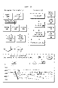
[0076] In the example of Fig. 4, a 2D region may be a multisegment region
where multiple segments represent a natural fracture. As an example, the
method
400 may include representing entities such as wells, artificial fractures,
etc. In such
19
CA 02838190 2013-12-23
1S12.2677-CA-NP
an example, the blocks 420 and 430 may provide for appropriate connections and
boundary conditions, respectively.
[0077] The method 400 is shown in Fig. 4 in association with various
computer-readable media (CRM) blocks 411, 421, 431, 441 and 451. Such blocks
generally include instructions suitable for execution by one or more
processors (or
processor cores) to instruct a computing device or system to perform one or
more
actions. While various blocks are shown, a single medium may be configured
with
instructions to allow for, at least in part, performance of various actions of
the
method 400. As an example, a computer-readable medium (CRM) may be a
computer-readable storage medium.
[0078] As an example, a method can include identifying a discrete natural
fracture in a three-dimensional environment that includes a reservoir, the
subterranean formation and the reservoir modeled by a three-dimensional grid
model; representing the discrete natural fracture via a multisegment model in
a two-
dimensional region within the three-dimensional grid model; defining at least
one
connection for fluid communication between the multisegment model and the
three-
dimensional grid model; defining boundary conditions for the multisegment
model;
and solving the multisegment model subject to the at least one connection and
the
boundary conditions to provide values for fluid flow in the two-dimensional
region.
As an example, such a method may include solving for the three-dimensional
grid
model for fluid flow based at least in part on the values for fluid flow in
the two-
dimensional region.
[0079] As an example, a method can include defining at least one connection
for fluid communication between a multisegment model and a well, the well
modeled
by another multisegment model. Such a method may also include solving the
multisegment models to provide values for fluid flow in at least a two-
dimensional
region.
[0080] As an example, a method can include formulating a plan for creation
of
an artificial fracture based at least in part on values for fluid flow in a
two-dimensional
region that represents a natural fracture. As an example, a method can include
representing an artificial fracture via a multisegment model in a two-
dimensional
region within a three-dimensional grid model and solving multiple multisegment
models to provide values for fluid flow two-dimensional regions.
CA 02838190 2013-12-23
IS12.2677-CA-NP
[0081] As an example, a method can include defining at least one connection
for fluid communication between a multisegment model and a three-dimensional
grid
model by defining a connection for fluid communication between a discrete
natural
fracture and a reservoir. In such an example, the reservoir can include fluid
and
values for fluid flow in a two-dimensional region may represent flow of fluid
from the
reservoir to the discrete natural fracture, from the discrete natural fracture
to the
reservoir or a combination of both.
[0082] As an example, a three-dimensional grid model may account for at
least some fractures in a three-dimensional environment using a continuum
model.
In such an example, other fractures may be considered discrete and modeled
using
a multisegment model or models.
[0083] Fig. 5 shows an example of a method 500 that includes an
identification block 510 for identifying one or more 2D regions in a 3D
environment
with one or more reservoirs, a model block 514 for modeling one or more wells
in the
3D environment with one or more reservoirs, a definition block 520 for
defining one
or more connections of entities in the 3D environment (e.g., wells, fractures,
reservoirs, etc.), a definition block 530 for defining boundary conditions for
at least
some of the entities in the 3D environment, and a solution block 540 for
solving for
flow (e.g., subject to the boundary conditions).
[0084] As an example, a 2D region may be a multisegment region that
represents an existing fracture (e.g., natural or artificial or a hybrid
thereof), a
prospective fracture, etc. As to the model block 514, modeling may be for an
existing well, a prospective well, a modification to an existing well, etc. As
an
example, a multisegment model may include at least one natural fracture and at
least one well, whether existing, prospective, etc.
[0085] In the example of Fig. 5, the method 500 includes a decision block
550
for deciding whether data exist for one or more existing wells. As an example,
where
the decision block 550 decides that such data exists, the method 500 may
continue
to a history matching block 560 for performing history matching (e.g., to
compare a
solution of the solution block 540 to data). Thereafter, the method 500 may
continue
at a continuation block 570, which may continue to a loop action or other
action. As
an example, where the decision block 550 decides that sufficient data does not
exist
(e.g., for purposes of history matching), the method 500 may continue to the
continuation block 570.
21
CA 02838190 2013-12-23
IS12.2677-CA-NP
[0086] The method 500 is shown in Fig. 5 in association with various
computer-readable media (CRM) blocks 511, 515, 521, 531, 541, 551 and 561.
Such blocks generally include instructions suitable for execution by one or
more
processors (or processor cores) to instruct a computing device or system to
perform
one or more actions. While various blocks are shown, a single medium may be
configured with instructions to allow for, at least in part, performance of
various
actions of the method 500. As an example, a computer-readable medium (CRM)
may be a computer-readable storage medium.
[0087] Fig. 6 shows an example of a system 600, examples of various
modules 610 and an example of a fracture network 680. In the example of Fig.
6,
the system 600 includes one or more processors 602 operatively coupled to
memory
604. As an example, the memory 604 may store modules such as one or more of
the modules 610, which may provide for modeling storage, flow, etc., in a
subterranean environment. In the example of Fig. 6, the modules 610 include a
fluid
reservoir module 612, a dry reservoir module 614, a module for existing wells
622, a
module for prospective wells 624, a natural fracture module 642, an artificial
fracture
module 644 and one or more solver modules 660. In the example of Fig. 6, the
modules 610 may include instructions suitable for execution by one or more of
the
processors (e.g., processor cores) to instruct a computing device or system to
perform one or more actions. For example, the system 600 may be instructed by
instructions of one or more of the modules 610.
[0088] As an example, a method can include implementing one or more of the
module 610 to represent a network such as the fracture network 680. In the
example of Fig. 6, the fracture network 680 includes natural fractures and
artificial
fractures. As an example, creation of a hydraulic fracture may be impacted by
one
or more natural fractures. For example, hydraulic fracture growth may proceed
in a
northeast-southwest direction that reactivates natural fractures (dashed
lines)
trending in another direction or directions (see, e.g., arrows indicate
possible
propagation directions of hydraulic fractures).
[0089] As an example, a method can include modeling of natural fractures in
an environment using a multisegment model and solving the multisegment model
for
storage, flow, etc., for example, with respect to a reservoir or reservoirs.
In turn, a
solution may be analyzed for prospective artificial fractures. Such an
analysis may,
for example, include positioning of one or more wells for creating one or more
22
CA 02838190 2013-12-23
1S12.2677-CA-NP
prospective artificial fractures with respect to one or more natural fractures
to
generate a network that acts to reactivate natural fractures as conduits for
flow of
fluid. As an example, such an analysis may aim to avoid certain natural
fractures
and reactivate (e.g., utilize) other natural fractures. In such an example,
refinement
of natural fracture locations, properties, etc., may occur using a
multisegment model
optionally in conjunction with a 3D grid model that models one or more
reservoirs.
[0090] As an example, a model may account for stress or one or more other
factors that may relate to fracturing. As an example, a multisegment natural
fracture
model may be mathematically linked to a stress model for a 3D environment. As
an
example, a model may account for a chemical process (e.g., acidizing). As an
example, a multisegment natural fracture model may be mathematically linked to
a
chemical reaction model for modeling a chemical process (e.g., with respect to
one
or more fracture characteristics). Where history matching is performed for
flow
based at least in part on a solution to a multisegment natural fracture model,
refinements to the multisegment natural fracture model may act to update one
or
more parameters associated with stress (e.g., direction, etc.).
[0091] As an example, a system can include one or more processors for
processing information, memory operatively coupled to the one or more
processors
and modules that include instructions storable in the memory and executable by
at
least one of the one or more processors. Such modules may include a reservoir
module for modeling a reservoir in a subterranean three-dimensional
environment
via a three-dimensional grid model, a natural fracture module for modeling a
natural
fracture via a multisegment model in a two-dimensional region, a well module
for
modeling a well via a multisegment model, and one or more solver modules for
solving for values of fluid flow in a fracture network based at least in part
on
modeling a natural fracture via a multisegment model. As an example, a system
may include an artificial fracture module for modeling an artificial fracture
via a
multisegment model in a two-dimensional region. As an example, a system may
include a solver module for solving for values of fluid flow in a fracture
network that
includes at least one natural fracture and at least one artificial fracture.
[0092] As mentioned, boundary conditions may be defined (e.g., imposed) on
one or more segments of a multisegment model that models a natural fracture,
natural fractures, etc. Fig. 7 shows an example of an environment 710 that
includes
various formations, a wellbore and natural fractures. As indicated, the
formations
23
CA 02838190 2013-12-23
IS12.2677-CA-NP
include fluid such as oil, gas and/or water, which may define various zones.
As to
boundary conditions, a natural fracture may include a natural fracture to
natural
fracture boundary condition, a natural fracture to oil filled formation
boundary
condition, a natural fracture to wellbore boundary condition, a natural
fracture to a
gas-filled formation boundary condition, a natural fracture to a water filled
formation
boundary condition, etc. As an example, a natural fracture may include
multiple
boundary conditions, for example, for both a wellbore and a fluid filled
formation.
[0093] As an example, a formation may be considered fluid filled or void
(e.g.,
"dry") depending on type of fluid. For example, a gas filled formation may be
considered void with respect oil where a goal is to produce oil. As indicated
by the
example environment 710 of Fig. 7, oil and water may coexist within a
formation and
a strategy may be formulated to produce oil with minimal water content. As an
example, such a strategy may be honed via use of a multisegment that models
one
or more natural fractures with respect to an environment (e.g., to avoid
activation of
a natural fracture that may lead to increase of water content in oil).
[0094] Fig. 8 shows an example of a graphical user interface (GUI) 810 that
provides for display of a grid 812, wells 814 and 818 and fractures 815 and an
example of a GUI 830 that provides for display of a grid 832, wells 834 and
838, a
fracture 835 and a scale 836.
[0095] As to the GUI 810, it may also provide for viewing the various
entities in
another view such as a plan view in an x,y-plane. The GUI 810 may include one
or
more data fields, for example, for input of parameters associated with
fractures 815.
For example, a fracture field depth may be specified along a depth dimension
and a
fracture field orientation may be specified with respect to a direction (e.g.,
optionally
an angle). As mentioned, natural fractures may occur as clusters or corridors,
which
may be oriented in a general direction (e.g., responsive to past stress,
etc.). In the
example of Fig. 8, the GUI 810 may provide for orienting a field as whole or
individual fractures within a cluster or corridor.
[0096] As to the GUI 830, the natural fracture 835 is represented as a 2D
grid
along with various values, which may be properties assigned to the 2D grid,
solutions to a model for the 2D grid, etc. For example, the various values as
indicated by the scale 836 may represent static properties (e.g.,
permeability, etc.),
dynamic values (e.g., from a simulation, etc.). As an example, a GUI may
present
pressure values, saturation values (e.g., percentage of a phase in a
multiphase fluid
24
CA 02838190 2013-12-23
IS12.2677-CA-NP
system), porosity values, flow values or other values associated with a Darcy
model
or other model. Such values may be presented directly on a 2D grid. As an
example, a GUI may include a graphic control that for allows for selection of
one or
more types of values and display of such values (e.g., using color, hatching,
contours, etc.) with respect to a grid that represents a fracture. In such a
manner, a
user may interact with the GUI to visualize values to determine a strategy,
hone a
strategy, update a model, etc. As an example, a visualization may be presented
as
a series of images with respect to time (e.g., a movie), for example, to
illustrate flow,
change in one or more properties, phase composition, etc. with respect to
time.
[0097] As an example, the 2D grid may include 25 or more segments, which
may be Darcy segments where each Darcy segment includes property values. In
such an example, boundary conditions may be specified for at least some of the
segments. For example, where the well 834 connects to the fracture 835, the
segments along that boundary may include appropriate boundary conditions. As
another example, where the well 838 connects to the fracture 835, the segments
along that boundary may include appropriate boundary conditions.
[0098] As an example, the well 834 may be specified to be a producer well
while the well 838 may be specified to be an injector well. In such an
example, a
multisegment model may model fluid flow in the fracture 835 (e.g., the 2D
grid) given
conditions as to injection of fluid via the injector well 838. In such an
example, the
fracture 835 may include boundary conditions that avoid movement of fluid to
the
surface (e.g., one or more boundaries).
[0099] As an example, the natural fracture 835 may include one or more
boundary conditions that mathematically link it to a reservoir modeled by the
3D grid
832. As an example, where the well 838 is specified to be an injector well, it
may
inject a fluid such as water that causes movement of oil from an oil reservoir
in fluid
communication with the natural fracture 835 to flow to the well 834, which may
be
specified to be a producer well. In such an example, the 2D grid may be
displayed in
the GUI 830 to indicate presence of a fluid, a fluid phase, fluid pressure,
fluid flow,
etc.
[00100] The GUIs 810 and 830 are shown in Fig. 8 in association with
various
computer-readable media (CRM) blocks 811 and 831. Such blocks generally
include
instructions suitable for execution by one or more processors (or processor
cores) to
instruct a computing device or system to perform one or more actions. While
various
CA 02838190 2013-12-23
IS12.2677-CA-NP
blocks are shown, a single medium may be configured with instructions to allow
for,
at least in part, performance of various actions associated with rendering the
GUIs
810 and 830. As an example, a computer-readable medium (CRM) may be a
computer-readable storage medium.
[00101] Fig. 9 shows an example of a method 900 that includes a model block
910 for modeling at least natural fractures, a generation block 920 for
generating
simulation results for at least the natural fractures, a model block 930 for
modeling
artificial fractures based at least in part on the simulation results, a
generation block
940 for generating simulation results for at least the artificial fractures
and a plan
block 950 for planning for or creating one or more artificial fractures based
at least in
part on the simulation results (e.g., for at least the natural fractures, for
at least the
artificial fractures, etc.).
[00102] The method 900 is shown in Fig. 9 in association with various
computer-readable media (CRM) blocks 911, 921, 931, 941 and 951. Such blocks
generally include instructions suitable for execution by one or more
processors (or
processor cores) to instruct a computing device or system to perform one or
more
actions. While various blocks are shown, a single medium may be configured
with
instructions to allow for, at least in part, performance of various actions of
the
method 900. As an example, a computer-readable medium (CRM) may be a
computer-readable storage medium.
[00103] Fig. 10 shows an example of a solution scheme 1010 and an example
of a method 1020. The solution scheme 1010 includes providing solution results
for
a fracture model 1018 to a reservoir model 1012. In the example of Fig. 10,
the
method 1020 pertains to the solution scheme 1010. In a grid block 1030, the
method
1020 grids one or more fracture regions (e.g., to form one or more networks).
For
example, the block 1030 may grid one or more regions with multiple segments
1040
where each segment may be a Darcy (or fracture) segment 1046 or optionally
another type of segment (e.g., well segment 1042, a fracture-wellbore segment
1044, etc.).
[00104] As shown in the example of Fig. 10, the method 1020 includes a
solution block 1050 for solving a system of equations for fracture regions.
The
system of equations 1060 may include, for example, well equations 1062,
fracture/well equations 1064, Darcy equations 1066 and fracture/formation
equations
1068 (e.g., connection equations). As an example, formulated equations for
various
26
CA 02838190 2013-12-23
IS12.2677-CA-NP
phenomena in a fracture system may be solved simultaneously to convergence. A
solution to such a system of equations may be by itself of use for field
management
or other management purposes.
[00105] In the example of Fig. 10, the method 1020 includes an introduction
block 1070 for introducing a solution to a fracture model to a comprehensive
reservoir simulation (e.g., in accord with the solution scheme 1010). The
method
1020 also includes a solution block 1090 for solving the comprehensive
reservoir
simulation, for example, as modeled using a three-dimensional grid.
[00106] The method 1020 also shows circuitry or computer-readable medium
blocks 1035, 1055, 1075 and 1095, which may be physical components (e.g.,
actual
circuitry, storage devices, combinations thereof, etc.) configured to perform
actions
of their corresponding method blocks 1030, 1050, 1070 and 1090.
[00107] As an example, one or more computer-readable storage media can
include computer-executable instructions to instruct a computing system to:
grid one
or more natural fracture regions with respect to a three-dimensional grid
model of a
subterranean formation that comprises a reservoir, the one or more natural
fracture
regions represented via multiple segments; solve a system of equations
associated
with the multiple segments to provide a solution; introduce the solution as
input to a
system of equations associated with the three-dimensional grid model; and
solve the
system of equations associated with the three-dimensional grid model. In such
an
example, one or more computer-readable media may include computer-executable
instructions to instruct a computing system to grid the one or more natural
fracture
regions for individual natural fractures of a natural fracture corridor.
[00108] As an example, one or more computer-readable media may include
computer-executable instructions to instruct a computing system to render
representations of the natural fracture corridor to a display. In such an
example,
instructions may be included to instruct a computing system to render
graphical
controls to the display for receipt of commands to orient the natural fracture
corridor
with respect to the three-dimensional of the subterranean formation.
[00109] Fig. 11 shows an example of a solution scheme 1100 and an example
of a method 1110. The solution scheme 1100 includes providing a fracture model
that models one or more fractures 1106, for example, as a network or networks.
The
scheme 1100 provides for solving the fracture model and introducing the result
to a
model that models a reservoir 1102.
27
CA 02838190 2013-12-23
IS12.2677-CA-NP
[00110] In the examples of Fig. 11, a set of fracture equations can be
solved
together and independently of a set of reservoir grid cell equations for each
nonlinear
iteration of a combined system of reservoir and fracture equations. From a
reservoir
grid solution viewpoint, such an approach has the effect of solving the
reservoir
system given a locally converged solution of at least one fracture system and
optionally multiple fracture systems associated with a reservoir.
[00111] The method 1110 includes a provision block 1114 that provides
reservoir equations and a provision block 1118 that provides fracture
equations. A
solution block 1122 includes (a) solving the fracture equations followed by
(b) solving
reservoir equations. An example of an approach for performing various actions
of
block 1122 is presented with respect to blocks 1126 to 1142. Thereafter, the
method
1110 provides, per an output block 1146, a solution for a time "T".
[00112] In the example of Fig. 11, the solution block 1122 can implement
nested loops that act to converge solutions to various equations. An outer
loop acts
to converge a solution to reservoir equations via a decision block 1142, an
inner loop
acts to converge a solution to equations for fractures via a decision block
1134, and
an innermost loop acts to converge a solution to equations for a particular
fracture
system via a decision block 1130. Accordingly, the blocks 1126 to 1142 can
begin
with initialization of fracture equations per block 1126 (e.g., optionally
based on
output from a reservoir model simulator), followed by converging solutions for
each
particular fracture system and then globally converging the solutions for
multiple
fracture systems. After convergence of fracture systems, an update block 1138
may
update unknowns for reservoir equations (e.g., independent variables). A
simulator
may solve the reservoir equations by a technique that iterates values of the
unknowns until convergence. Once converged, the result may be output per the
output block 1146. Such a result aims to include a global solution for a
reservoir
including associated fracture systems.
[00113] Fig. 11 also shows various computer-readable media blocks (CRM)
1116, 1120, 1124, 1125 and 1148, which correspond to method blocks 1114, 1118,
1122 and 1146, respectively. While blocks are shown individually, a single
computer-readable may include instructions of blocks 1116, 1120, 1124, 1125
and
1148.
[00114] Fig. 12 shows components of an example of a computing system 1200
and an example of a networked system 1210. The system 1200 includes one or
28
CA 02838190 2013-12-23
1S12.2677-CA-NP
more processors 1202, memory and/or storage components 1204, one or more input
and/or output devices 1206 and a bus 1208. In an example embodiment,
instructions may be stored in one or more computer-readable media (e.g.,
memory/storage components 1204). Such instructions may be read by one or more
processors (e.g., the processor(s) 1202) via a communication bus (e.g., the
bus
1208), which may be wired or wireless. The one or more processors may execute
such instructions to implement (wholly or in part) one or more attributes
(e.g., as part
of a method). A user may view output from and interact with a process via an
I/O
device (e.g., the device 1206). In an example embodiment, a computer-readable
medium may be a storage component such as a physical memory storage device,
for example, a chip, a chip on a package, a memory card, etc. (e.g., a
computer-
readable storage medium).
[00115] In an example embodiment, components may be distributed, such as in
the network system 1210. The network system 1210 includes components 1222-1,
1222-2, 1222-3, . . 1222-N. For example, the components 1222-1 may include the
processor(s) 1202 while the component(s) 1222-3 may include memory accessible
by the processor(s) 1202. Further, the component(s) 1202-2 may include an I/O
device for display and optionally interaction with a method. The network may
be or
include the Internet, an intranet, a cellular network, a satellite network,
etc.
[00116] Although only a few example embodiments have been described in
detail above, those skilled in the art will readily appreciate that many
modifications
are possible in the example embodiments. Accordingly, all such modifications
are
intended to be included within the scope of this disclosure as defined in the
following
claims. In the claims, means-plus-function clauses are intended to cover the
structures described herein as performing the recited function and not only
structural
equivalents, but also equivalent structures. Thus, although a nail and a screw
may
not be structural equivalents in that a nail employs a cylindrical surface to
secure
wooden parts together, whereas a screw employs a helical surface, in the
environment of fastening wooden parts, a nail and a screw may be equivalent
structures. It is the express intention of the applicant not to invoke 35
U.S.C. 112,
paragraph 6 for any limitations of any of the claims herein, except for those
in which
the claim expressly uses the words "means for" together with an associated
function.
29