Note: Descriptions are shown in the official language in which they were submitted.
CA 02838250 2015-06-26
PROTECTIVE CASE FOR PHYSICALLY
SECURING A PORTABLE ELECTRONIC DEVICE
CROSS-REFERENCES TO RELATED APPLICATIONS
The Patent Cooperation Treaty application claims the benefit of priority of
U.S. Non-
Provisional Application No. 13/450,801, filed on April 19, 2012, which claims
the benefit of
priority of U.S. Provisional Application No. 61/496,981, filed on June 14,
2011, where U.S.
Non-Provisional Application No. 13/450,801 corresponds to U.S. Patent
Application
Publication No. 2012/0317779 and to U.S. Patent 8,869,573.
BACKGROUND
Embodiments of the present invention relate to devices for inhibiting the
theft of relatively
small but expensive pieces of equipment, such as iPadsTM, iPhonesTM, similar
mobile
computing devices, tablets, laptops, or electronic devices without a security
slot (e.g., a
Kensington security slot).
Electronic devices are commonly used for a variety of applications. Many
electronic devices
are small and valuable, making them attractive to steal. One way to deter
computer theft is to
provide a small, generally rectangular slot in a wall of a computer. A
security apparatus with a
locking head may be secured to the computer via the rectangular slot. However,
many
electronic devices do not include this rectangular slot. For example,
iPhonesTM and iPadsTM,
each of which may retail for hundreds of dollars, do not include this
rectangular slot. Owners
may desire to nonetheless secure these devices to a semi-permanent or
permanent fixture.
Embodiments of the invention address these and other problems, individually
and collectively.
BRIEF SUMMARY
Embodiments of the invention relate to security apparatuses, as well as
methods for making
and using security apparatuses.
CA 02838250 2015-06-26
In some embodiments, a security apparatus for a portable electronic device is
provided. The
security apparatus may include a plurality of shell portions, each shaped to
wrap around part
of a perimeter of the portable electronic device. The security apparatus may
further include a
connecting portion that engages at least one of the plurality of shell
portions and to thereby
couple the plurality of shell portions to each other. At least one of the
connecting portion and
one or more of the plurality of shell portions may include an attachment
device, the
la
CA 02838250 2013-12-03
WO 2012/173764
PCT/US2012/039414
attachment device being configured to engage with a locking head, thereby
locking relative
positions of the plurality of shell portions and the connecting portion. The
locking head may
be coupled to a cable. The locking head may be independent from the shell
portions and may
be independent from the connecting portion. The locking head may be configured
to change
from a locked state to an unlocked state upon completed entry of a security
feature into the
locking head. The plurality of shell portions may be configured to, in total,
cover a
substantial portion of a back of the portable electronic device when the
portions are
assembled around the portable electronic device. Another of the connecting
portion and one
or more of the plurality of shell portions may include an aperture that aligns
with the
attachment device when the plurality of shell portions and the connecting
portions are
assembled around the portable electronic device. The connecting portion may be
configured
to be positioned on at least part of at least two of the plurality of shell
portions. The
connecting portion may include the attachment device. One of the plurality of
shell portions
may include the attachment device. One or more of the plurality of shell
portions may
include one or more tracks, and the connecting portion may include one or more
runners
complementary to the one or more tracks. The plurality of shell portions, in
some instances,
do not comprise the connecting portion. The connecting portion may include a
bar with a
length-to-width aspect ratio greater than about 1.5.
In some embodiments, a method of securing a portable electronic device is
provided. The
method may include positioning each of a plurality of shell portions to
surround a respective
part of a perimeter of the electronic device. The method may further include
engaging a
connecting portion with each of the plurality of shell portion. The method may
also include
locking a locking head to an attachment device, thereby restricting relative
movement of each
of the plurality of shell portions relative to each other, wherein at least
one of the connecting
portion and one or more of the plurality of shell portions comprises the
attachment device.
Upon engagement of the connecting portion with each of the plurality of shell
portions, the
attachment device may extend through an aperture in another of the connecting
portion and
one or more of the plurality of shell portions. The method may further include
coupling the
locking head with an immovable object prior to locking the locking head to the
attachment
device. Coupling the locking head with the immovable object may include
wrapping a cable
coupled to the locking head around the immovable object. The method may also
include
unlocking the locking head from the attachment device by entering a security
feature into the
locking head.
2
CA 02838250 2015-06-26
In some embodiments, a security apparatus for a portable electronic device is
provided. The
security apparatus may include: a plurality of interconnecting frame portions
that assemble to
interconnect and at least partly enclose the portable electronic device, where
the plurality of
interconnecting frame portions comprise at least three frame portions, at
least two of the frame
portions each comprising an aperture. The security apparatus may also include
a locking
feature sized to fit through the apertures. Upon assembly of the
interconnecting frame portions
around the portable electronic device, the apertures may be aligned with each
other. Upon the
assembly of the interconnecting frame portions around the portable electronic
device, a space
may be formed between a surface of the portable electronic device and a
surface of each of the
at least two of the frame portions. At least two of the plurality of
interconnecting frame
portions may be shaped to wrap around part of a perimeter of the portable
electronic device.
The plurality of interconnecting frame portions may be configured to, in
total, cover a
substantial portion of a back of the portable electronic device when the
portions are assembled
around the portable electronic device. The locking feature may be coupled to a
cable.
According to one aspect, the present invention relates to a security apparatus
for a portable
electronic device. The security apparatus includes a plurality of shell
portions, each shaped to
wrap around part of a perimeter of the portable electronic device. The
security apparatus also
includes a connecting portion that engages at least one of the plurality of
shell portions to
couple the plurality of shell portions to each other, the connecting portion
defining an
aperture. The security apparatus further includes an attachment device secured
to one of the
plurality of shell portions, the attachment device extending through the
aperture of the
connecting portion when the plurality of shell portions and the connecting
portion are coupled
together and a locking head engageable with the attachment device to secure
the plurality of
shell portions and the connecting portion together.
According to another aspect, the present invention relates to a method of
securing a portable
electronic device. The method includes positioning each of a plurality of
shell portions to
surround a respective part of a perimeter of the electronic device, wherein an
attachment
device is secured to one of the plurality of shell portions. The method also
3
CA 02838250 2015-06-26
includes engaging a connecting portion with each of the plurality of shell
portions to couple
the plurality of shell portions to each other, the connecting portion defining
an aperture. The
method further includes extending the attachment device through the aperture
of the
connecting portion and locking a locking head to the attachment device to
secure the plurality
of shell portions and the connecting portion together.
According to still another aspect, the present invention relates to a security
apparatus for a
portable electronic device having a front and a back, the front of the
portable electronic device
including a screen. The security apparatus includes: a plurality of
interconnecting frame
portions that assemble to interconnect and at least partly enclose the
portable electronic
device, where the plurality of interconnecting frame portions comprise at
least three frame
portions, at least two of the frame portions each comprising an aperture; and
a locking feature
sized to fit through the apertures, wherein, upon assembly of the
interconnecting frame
portions around the portable electronic device, the apertures are aligned with
each other; and
wherein the plurality of interconnecting frame portions are configured to, in
total, cover a
substantial portion of the back of the portable electronic device when the
interconnecting
frame portions are assembled around the portable electronic device.
These and other embodiments of the invention are described in further detail
below.
BRIEF DESCRIPTION OF THE DRAWINGS
FIG. 1 shows a system according to an embodiment of the invention.
FIG. 2a shows a rear perspective view including a portion of a portable
electronic device and
parts of an unconstructed security shell according to an embodiment of the
invention.
FIG. 2b shows a rear perspective view including a portion of a portable
electronic device and
parts of a constructed security shell according to an embodiment of the
invention.
FIG. 2c shows a rear perspective view including a portion of a portable
electronic device and
parts of a constructed security shell according to an embodiment of the
invention.
3a
CA 02838250 2015-06-26
FIG. 3 shows a rear perspective view including a portion of a portable
electronic device and
parts of a constructed security shell.
FIG. 4 shows a rear perspective of a portion of a security shell.
FIG. 5 shows a cross-section of a portion of a security shell.
FIG. 6a shows a rear perspective view of a partly constructed security shell.
3b
CA 02838250 2013-12-03
WO 2012/173764
PCT/US2012/039414
FIG. 6b shows a rear perspective view of a constructed and unlocked security
shell.
FIG. 6c shows a rear perspective view of a constructed and locked security
shell.
FIG. 7a shows a front perspective view of a key and a locking head.
FIG. 7b shows a rear perspective view of a locking head.
FIG. 8 shows a front perspective of a constructed and locked security shell.
FIG. 9 shows a rear perspective view of an unconstructed security shell
according to an
embodiment of the invention.
FIG. 10 shows a front perspective view of a constructed security shell.
FIG. 11 shows a side perspective view of a constructed security shell.
FIG. 12 shows a flowchart illustrating a method of using a security apparatus
according to an
embodiment of the invention.
FIG. 13 shows a flowchart illustrating a method of using a security apparatus
according to an
embodiment of the invention.
DETAILED DESCRIPTION
Embodiments of the invention are directed to security apparatuses, methods for
making and
using such security apparatuses, and systems using such security apparatuses.
The security
apparatuses can be used to prevent or deter the theft of devices such as
portable electronic
devices.
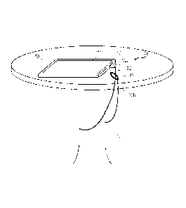
FIG. 1 shows a system comprising a portable electronic device 30 and a
security apparatus 26
that is used to secure the portable electronic device 30 to an immovable
object 10 such as a
desk leg or the like. The security apparatus 26 includes a plurality of shell
portions that are
assembled by a user to at least partly encase the portable electronic device
30, thereby
forming a frame 72 around the portable electronic device 30. The frame
configuration may
allow a user to continue to view, e.g., a screen or monitor on a front side of
the portable
electronic device 30 and access input components of the portable electronic
device 30 even
while it is secured. In other embodiments, the security apparatus may be
configured to more
fully or completely encase the portable electronic device 30. Such alternative
configurations
may be advantageous to, e.g., reduce the probability that a potential thief
will spot and
identify the portable electronic device 30.
4
CA 02838250 2013-12-03
WO 2012/173764
PCT/US2012/039414
The security apparatus 26 comprises a locking head 120 and a cable 32 coupled
to a first end
32a to the locking head 120. A loop 34 is at a second end 32b of the cable 32.
The cable 32
may comprise a strong material such as stainless steel or KevlarTm. To secure
the portable
electronic device 30 to the immovable object, the cable 32 may be wrapped
around the
immovable object and the locking head 120 may pass through the loop 34. The
locking head
120 engages a portion of the frame 72, thereby coupling the cable 32 to the
frame 72 and the
enclosed portable electronic device 30.
Other configurations in which the security apparatus 26 (and the portable
electronic device
30) may be secured to an immovable object 10 are further contemplated. FIG. 1
shows an
embodiment in which the first end 32a of cable 32 is fixedly attached to the
locking head 120
and the second end 32b of the cable 32 includes a loop 34 and does not
directly engage with
the locking head 120.
In some instances, there is no loop 34 at the second end 32b of the cable 32.
For example,
the cable 32 may be configured such that both the first end 32a and the second
end 32b of the
cable couple to the locking head 120. The locking head 120 may include a cable-
receiving
aperture. The cable 32 may then be looped around the immovable object 10 and
an insertion
component at the second end 32b may be inserted into the cable-receiving
aperture, thereby
locking the second end of the cable 32 to the locking head 120. Engagement of
security
feature, such as a key or code, with the locking head 120 may unlock the
second end of the
cable 32 from the locking head 120.
In some instances, each of the first end 32a and the second end 32b are
coupled to a locking
head 120. Each locking head 120 may engage different portions of the frame
(e.g., such that
two locking heads 120 may engage with two bottom portions of the frame 72).
In some instances, the second end 32b of the cable 32 may be configured such
that it may be
sandwiched between the portable electronic device 30 (and potentially the
frame 72) and the
locking head 120. For example, the second end 32b may include a flat loop. The
flat loop
may be positioned over an engagement portion of the frame 72, and the locking
head 120
may then engage with the frame, sandwiching the loop between the locking head
120 and the
frame 72.
FIG. 2a shows a back view of a portable electronic device 30 secured by a
security apparatus
according to an embodiment of the invention. As shown, the security apparatus
may include
interlocking frame portions forming a protective shell that partly or fully
encapsulating the
5
CA 02838250 2013-12-03
WO 2012/173764
PCT/US2012/039414
portable electronic device 30. The frame portions may include a plurality of
shell portions
(e.g., a top portion 40a and a bottom portion 40b) and a connecting portion
44. The
connecting portion 44 may be independent from the top and bottom portions 40a
and 40b (as
shown in FIG. 2a) or may be a part of one of the top and bottom portions 40a
and 40b (e.g., a
plate with an aperture hinged to one of the top and bottom portions 40a and
40b). The
connecting portion 44 may include a bar, which may have a length-to-width
aspect ratio
between about 1.5 and 20. The top and bottom portions 40a and 40b may be
configured to
engage and interlock with the connecting portion 44. For example, each of the
top and
bottom portions 40a and 40b may include a receiving feature 48 configured to
receive the
connecting portion 42. A receiving feature 48 of the top portion 40a may be
partly or
substantially complementary in shape to a receiving feature 48 of the bottom
portion 40b,
such that a substantial portion (e.g., at least 80%, 90% or 95%) of a bottom
edge of the top
portion 40a is in contact with a substantial portion (e.g., at least 80%, 90%
or 95%) of a top
edge of the bottom portion 40b when the portions are fully engaged with the
portable
electronic device 30. In the embodiment shown in FIG. 2, the receiving
features 48 are raised
relative to the rest of the top and bottom portions 40a and 40b.
One or more receiving features 48 may include a track 52 to receive a runner
56 on the
connecting portion 44. For example, a receiving feature 48 of the top portion
40a and a
receiving feature 48 of the bottom portion 40b may include a track 52. In one
embodiment, a
track 52 of the top portion 40a is configured to combine with a track 52 of
the bottom portion
40b to form a single combined track. In another embodiment, one or more tracks
52 are fully
contained within the top portion 40a or the bottom portion 40b. In total, one,
two or more
tracks may be formed by the combination of the top and bottom portions 40a and
40b, and the
connecting portion 44 may include one, two or more runners 56. The runners 56
can be in
the form of elongated rails in some embodiments.
The top portion 40a, bottom portion 40b and connecting portion 44 may be have
different
shapes and/or configurations in other embodiments than those shown in FIG. 2a.
Generally,
the portions may be configured such that the connecting portion 44 restrains
movement of the
top portion 40a relative to the bottom portion 40b, and such that locking a
locking head locks
the relative positions of the top portion 40a, bottom portion 40b and
connecting portion 44.
FIGS. 2b and 2c show back-view perspectives of alternative configurations.
6
CA 02838250 2013-12-03
WO 2012/173764
PCT/US2012/039414
FIG. 2b shows a back view of a portable electronic device 30 secured by a
security apparatus
according to another embodiment of the invention. As shown, the top portion
40a and
bottom portion 40b may be slid over opposite portions of the portable
electronic device 30.
A user may then slide the connecting portion 44 onto the top portion 40a and
bottom portion
40b. The top portion 40a may include a slit to receive a top region of the
connecting portion
44, and may be generally perpendicularly oriented with respect to the
orientation of the
connecting portion 44. The connecting portion 44 may include an aperture 64.
When the
connecting portion 44 is engaged with the other portions, an attachment device
110 may
extend through or align with the aperture 64. A locking head 120 (not shown)
may then lock
to the attachment device 110, either by locking to a protruding attachment
device 110 or
extending through the aperture to lock to a set-back attachment device 110,
thereby fixing the
top portion relative to the bottom portion and coupling an enclosed portable
electronic device
30 to the locking head 120.
In an alternative configuration, connecting portion 44 may be hingedly
attached to top portion
40a. The top portion 40a and the bottom portion 40b may again be slid over
opposite
portions of the portable electronic device 30. A user may then rotate the
connecting portion
44 to extend over the bottom portion. The connecting portion 44 may include
another hinge
separating the two segments of the portion that are shown to be perpendicular
in FIG. 2b.
Thus, a user may then rotate the smaller segment, such that the attachment
device 110
extends through the aperture 64 in the smaller segment or such that the
attachment device 110
is aligned with the aperture 64. A locking head 120 (not shown) may then
engage the
attachment device 110 (as described above), thereby fixing the top portion
relative to the
bottom portion and coupling an enclosed portable electronic device 30 to the
locking head
120.
FIG. 2c shows a back view of a portable electronic device 30 secured by a
security apparatus
according to yet another embodiment of the invention. Again, the top portion
40a and the
bottom portion 40b may be slid over opposite sites of a portable electronic
device 30. Each
of the top portion 40a and the bottom portion 40b may include an attachment
device 120.
The connecting portion 44 includes two apertures 64, such that the connecting
portion 44 can
be placed over the attachment device 110. One or more locking heads 120 (not
shown) may
then engage the attachment devices 110 and secure the top portion 40a, the
bottom portion
40b and the connecting portion 44 to each other and to a device positioned
inside the
portions.
7
CA 02838250 2013-12-03
WO 2012/173764
PCT/US2012/039414
The top portion 40a, bottom portion 40b and connecting portion 44 may be sized
to at least
partly wrap around a portable electronic device 30. Each portion may be
characterized by a
height dimension (extending along direction 62a in FIG. 2a) and a width
dimension
(extending along direction 62b in FIG. 2a). The top portion 40a and/or the
bottom portion
40b may each have one dimension (e.g., a width) that is slightly larger than
the same type of
dimension of a corresponding portable electronic device, and may have another
dimension
(e.g., a height) that combines between the two to be slightly larger than the
same type of
dimension of a corresponding portable electronic device. In one instance, a
first dimension
(e.g., a width) of the top portion 40a and/or the bottom portion 40b is about
1-15, 4-12, or 9-
11 inches. In one instance, a combined second dimension (e.g., a height) of
the top portion
40a and the bottom portion 40b is about 1-15, 2-10, or 7-9 inches. In one
instance, one of the
top portion 40a and the bottom portion 40b is about 9-10 inches wide and 4-6
inches in
height, and the other of the top portion 40a and the bottom portion 40b is
about 9-10 inches
wide and 2-4 inches in height.
The connecting portion 44 may have at least one dimension that is smaller the
same type of
dimension of a corresponding portable electronic device and/or smaller than
the same type of
dimension of one or both of the top portion 40a and the bottom portion 40b. In
one instance,
a first dimension (e.g., a width) of the connecting portion 44 is about 1-13,
2-11, or 8-10
inches, and a second dimension (e.g., a height) is about 0.5-7, 1-5 or 1-3
inches. In one
instance, the connecting portion 44 is about 8-10 inches wide and 1-3 inches
in height.
FIG. 3 shows the parts of the security apparatus shown in FIG. 2a in an
interlocking
constructed state. As shown, the top and bottom portions 40a and 40b may be
pushed
together towards a center axis of a portable electronic device. The connecting
portion 44 may
then engage the receiving features 48 of the top and bottom portions 40a and
40b, and
thereby connects the top and bottom portions together. The top and/or bottom
portion 40a or
40b may include an attachment device 110. The connecting portion may include
an aperture
64 that is larger than a cross-sectional area of the attachment device 110.
When the portions
are engaged, the attachment device 110 may protrude out of the connecting
portion's aperture
64. In other embodiments, the attachment device 110 may be set back relative
to an exterior
perimeter of the frame formed by the portions,
FIG. 4 shows an embodiment of a bottom portion 40b with an attachment device
110. The
attachment device 110 may be positioned on or near the receiving feature 48.
The attachment
8
CA 02838250 2013-12-03
WO 2012/173764
PCT/US2012/039414
device 110 may protrude laterally from a side of the bottom portion 40b (e.g.,
from a side of
the receiving feature 48). In some other embodiments, the attachment device
110 may
protrude outwards from a back of the bottom portion 40b, as shown in FIG. 2c.
The
attachment device 110 may be configured to engage a locking head. For example,
the
attachment device may include a recess, such as a recess 110b defined by a cap
110a and a
ring structure 110c. The cap 110a and the ring structure 110c may have similar
diameters. In
some implementations, the cap 110a and the ring structure 110c may each
comprise cylinders
with a substantially (axially) tapered end and a substantially flat end
opposite the
substantially tapered end. In other implementations, one or more ends of the
cap 110a or the
ring structure 110c may comprise a curved surface or other uneven shape (i.e.,
not flat). The
lateral side wall of each of the ring structure 110c and the cap 110a may be
tapered (as in a
cone shape) or may comprise a straight wall.
In the embodiment illustrated in FIG. 4, the cylinders comprising the ring
structure 110c and
the cap 110a are facing in the same direction. That is, the direction of
travel from the flat end
of the cap 110a to the tapered end of the cap 110a is the same direction of
travel as from the
flat end of the ring structure 110c to the tapered end of the ring structure
110c. That is, the
cap 110a and the ring structure 110c can be axially aligned. The recess 110b
can be formed
by the space between the tapered end of the ring structure 110c and the flat
end of the cap
110a, which may be joined together (and held apart to form the recess) by a
central cylinder.
Thus, the recess 110b may be located between the cap 110a and the ring
structure 110c. The
tapered end of the ring structure 110c may taper from the width of the ring
structure 110c to
the width of the central cylinder, at which point the ring structure 110c may
be joined to the
central cylinder. In some embodiments, the cap 110a and the ring structure
110c may have
approximately equal lengths. In some embodiments of the invention, the central
cylinder
may include a lateral side wall that may be tapered or may comprise a straight
wall.
In certain embodiments, the cap 110a, the central cylinder, and the ring
structure 110c may be
structurally discrete or non-discrete. That is, the cap 110a, the central
cylinder, and the ring
structure 110c may together be formed of one piece of material, such as one
machined metal
structure with tapered portions and a recess. In another embodiment, each of
the cap 110a,
the central cylinder, and the ring structure 110c may be formed separately,
and joined
together (such as by glue, rivets, pins, etc.). In a further embodiment, the
central cylinder and
either the cap 110a or the ring structure 110c may comprise one continuous
material, which
can be joined to the third portion. For example, the ring structure 110c and
the central
9
CA 02838250 2015-06-26
cylinder can be formed of a single machined metal part, and then be joined to
the cap 110a by
any suitable process (e.g., glue, rivets, pins, etc.).
The design of the attachment device 110, as disclosed herein, contains many
advantages. For
example, the flat end of the cap 110a (i.e., the recess-facing end) can
conform to the clamping
structure of a locking head. In certain embodiments, the flat end of the cap
110a can be a
substantially planar surface that is approximately 90 degrees from the lateral
side wall of the
cap 110a. This flat end of the cap 110a may be approximately parallel to a
side of the bottom
portion 40b, and the flat end structure will provide a strong surface for a
locking head to hold
onto while securing the portable electronic device 30. A locking head is
unlikely to be able to
slip or be pulled off of the cap 110a. Furthermore, the tapered ends of the
cap 110a and the
ring structure 110c may assist in guiding a locking head onto the correct
position around the
base while securing the portable electronic device 30, resulting in easier
locking and
unlocking by a user (as described in further detail below). The lateral side
wall(s) of the
attachment device 110, such as the lateral sidewalls of the cap 110a and the
ring structure
110c, may comprise a smooth surface, such as a polished metal surface. This
smooth surface
can allow a locking head to rotate about the attachment device, preventing a
person from
twisting the attachment device off the bottom portion 40b (i.e., forcibly
unsecuring the
security apparatus) by twisting the locking head. Nevertheless, attachment
devices varying in
design and/or operation from that described above may be used, such as those
described in
U.S. Patent Application Publication No. 2011/0072863 or U.S. Patent No.
7,997,106.
FIG. 5 shows a cross-section of the bottom portion 40b. The figure shows an
example of an
integration of the attachment device 110 with one frame portions (e.g., the
bottom portion
40b). In the depicted instance, the bottom portion's surface is formed around
the attachment
device 110. For example, plastic may be molded around the attachment device
110. The
attachment device 110 may include an extension 110d configured to reside
primarily inside a
surface of the shell. The extension may be substantially cylindrical. The
extension 110d may
include ribs. The bottom portion 40b may include indentations, which may be
positioned,
spaced and/or shaped in a complementary manner to ribs of the extension 110d.
Thus, the ribs
may prevent the attachment device 110 from being separated from the bottom
portion 40b.
CA 02838250 2015-06-26
FIG. 5 shows an embodiment in which the attachment device 110 is permanently
integrated
with the bottom portion 40b. In other embodiments, the attachment device 110
is an
independent component that may be latched into one or more frame portions or
latched into a
portable electronic device 30. Additionally or alternatively, the attachment
device 110 may be
integrated with another frame portion (e.g., the top portion 40a or connecting
portion 44).
FIGS. 6a-6c show exemplary operational modes of a security apparatus. In FIG.
6a, the
connecting portion 44 is not fully engaged with the receiving features 48 of
the top and
bottom portions 40a and 40b. Thus, the attachment device 110 is not yet
accessible. In FIG.
6b, the connecting portion 44 is fully engaged with the receiving features 48,
and the
attachment device 110 of the bottom portion 40b extends through the aperture
64 of the
connecting portion. In FIG. 6c, a locking head 120 is engaged with the
attachment device 110.
Thus, the connecting portion 44 cannot be removed from the top and bottom
portions 40a and
40b prior to disengaging the locking head 120 from the attachment device 110
(e.g., using a
key).
The locking head 120 may be configured to prevent a third party from
disassembling the
shell's parts and/or removing the portable electronic device 30 from one or
more frame
portions. The locking head 120 may be configured to attach to the attachment
device 110, e.g.,
by locking around the cap 110a. The locking head 120 may be configured to
release the
attachment device 110 upon entry of a security feature, such as insertion of a
key 121 into the
locking head 120 or entry of a code into the locking head 120.
FIG. 7a shows an exploded view of one exemplary locking head 120 and key 121.
A front
hole 4a in the head 120 may be configured to receive a cap 1 10a in the
attachment device
110. The head 120 may include any suitable dimensions, e.g., having a length,
height and/or
width of about 5-50mm. FIG. 7b shows a rear perspective view of the head 120.
A keyhole
122 is at a rear section of the head 120. Locking heads and/or keys varying in
design and/or
operation from that described above may be used, such as those described in
U.S. Patent
Application Publication No. 2011/0072863 or U.S. Patent 7,997,106.
11
CA 02838250 2015-06-26
FIG. 8 shows a front view of a portable electronic device 30 secured by a
security apparatus
according to an embodiment of the invention. One or more shell portions (e.g.,
top and bottom
portions 40a and 40b) may be configured to wrap around the portable electronic
device 30.
The combined shell portions may form a full or partial frame around the
portable electronic
device 30. Thus, when the shell portions are locked in this position (e.g., by
coupling the shell
portions via a connecting portion and engaging a locking feature), a third
party may be
prevented from separating the portable electronic device 30 from the shell and
1 la
CA 02838250 2013-12-03
WO 2012/173764
PCT/US2012/039414
from the locking head 120. A width of the created frame may be, e.g., about
0.5-5 cm. Thus,
a user of the device 30 may still be able to use the device while the security
apparatus is in
operation. The frame portions may be configured to cover all of the back of
the portable
electronic device (e.g., as shown in FIGS. 6a-6c) or to cover distinct regions
(e.g.,
corresponding to the device's motherboard) to prevent third parties from
stealing valuable
parts of the portable electronic device from the back. In some instances, the
connecting
portion 44 is positioned on at least a portion of a valuable device component
(e.g., a
motherboard). Thus, an attempt to forcibly separate the connecting portion 44
from the other
portions 40a and 40b is reasonably likely to damage the portable electronic
device. The
locking head 120 may be attached to a cable 32, which may be looped around or
attached to a
semi-permanent or permanent structure, as shown, e.g., in FIG. 1. In this
manner, a portable
electronic device 30 may be securely coupled to a fixed location.
FIGS. 2a-2c illustrate a variety of configurations in which a locking feature
may be extended
through an aperture 64 in a frame portion. In some instances, another frame
portion includes
an attachment device 110 that extends through the aperture 64 or is aligned
with the aperture
64 when the portions are in an engaged state. A locking head 120 may then
extend through
the aperture 64 to lock to an aligned attachment device 110 or may lock to an
attachment
device 110 protruding through the aperture 64. Thus, the above figures
illustrate
embodiments in which at least one of two engagable locking features (e.g.,
attachment device
110 or locking head 120) extend through an aperture 64 in a frame portion. In
other
embodiments, a locking feature extends through one or more apertures and can
lock the
frame portions relative to each other without engaging with another
complementary locking
feature. An example of this configuration is described with respect to FIGS. 9-
11.
FIG. 9 shows parts of a security apparatus according to another embodiment of
the invention.
In this embodiment, the raised receiving features 48 of the top and bottom
portions 40a and
40b are present at substantially the same lateral positions. In FIG. 9, the
raised receiving
features do not extend to the ends of the portions in the lateral direction.
In some
embodiments, only one portion has receiving features at a lateral position
surrounding the
aperture 64', while in other instances, this is not the case (e.g., and both
portions may include
an aperture). The connecting portion 44 may again include runners that may be
configured to
straddle the receiving features 48.
12
CA 02838250 2013-12-03
WO 2012/173764
PCT/US2012/039414
One or more of the frame portions may include an aperture. FIG. 9 shows an
embodiment in
which the connecting portion 44 includes an aperture 64 and the top portion
40a includes an
aperture 64'. The apertures may be configured to substantially overlap upon
full construction
of the portions.
FIG. 10 shows a front view of the constructed and interlocked parts (with the
electronic
device 30 not being shown). As shown, the portions' receiving features 48 may
form a
depression from this angle. The portions may be shaped to wrap around a device
and, in
essence, form a frame 72 around the device.
FIG. 11 shows a side view of an embodiment of the security apparatus shown in
FIGS. 9-10.
The top and bottom portions 40a and 40b may be positioned to be directly
adjacent to each
other. The receiving features 48 may comprise an L-shape, such that the
combination of the
top and bottom portions' receiving features 48 form a T-shape. Thus, spaces 76
may be
formed between the receiving features 48 and primary surfaces 40a' and 40b' of
the top and
bottom portions.
In operation, the connecting portion 44 may be slid over the receiving
features 48 of the top
and bottom portions 40a and 40b, such that an aperture 64 of the connecting
portion 44 is
aligned with an aperture 64' of one or both of the top and bottom portions 40a
and 40b. A
locking feature (e.g., independent from any frame portion) may be inserted
into the
overlapping apertures. The locking feature may include, e.g., an attachment
mechanism
which may physically move (e.g., rotate, expand and/or translationally move)
when entering
a locked state. Thus, a user may insert the locking feature (that may be,
e.g., attached to a
cable) through the apertures, and cause the attachment mechanism to enter the
locked state.
The locking-state movement of the attachment mechanism may prevent a thief
from pulling
the attachment mechanism back through the apertures to thereby decouple frame
(that at least
partly encloses a portable electronic device) from the attachment mechanism.
Because the
attachment mechanism may be coupled to a cable looped around an immovable
object, this
design may prevent the thief from stealing the portable electronic device.
The attachment mechanism may include, e.g., a configuration disclosed in U.S.
Patent
Number 7,121,125, which is hereby incorporated by reference in its entirety.
In one
embodiment, the attachment mechanism comprises a T-bar lock. The aperture may
be sized
and shaped such that it may receive a crossmember of the T-bar only when the
crossmember
is in a particular orientation (e.g., horizontally and not vertically). The T-
bar may be
13
CA 02838250 2013-12-03
WO 2012/173764
PCT/US2012/039414
appropriately oriented and the crossmember inserted through the apertures. The
T-bar may
then be rotated and locked in the rotated position. Thus, it may not be
possible to pull the
crossmember of the T-bar back through the aperture without first unlocking the
T-bar lock.
Further, because the crossmember extends through apertures in two frame
portions, the two
frame portions are locked together.
The locking feature (e.g., T-bar lock) may be connected to a cable that may be
wrapped
around a semi-permanent or permanent fixture. Entry of a security feature
(e.g., a key) into
the locking feature may again allow for the locking feature to be pulled back
through the
aperture and thereby allow the portable electronic device 30 to be removed
from the frame
portions.
In some embodiments, a security apparatus may include more than one of the
above-
described embodiments. For example, the embodiment shown in FIG. 2a may also
include
complementary apertures in the connecting bar 44 and the bottom portion 40b
which may be
sized and positioned to receive a T-bar lock. A user could then choose to
engage an
attachment device 110 extending through an aperture with a locking head and/or
to insert
another attachment mechanism (e.g., a T-bar lock) through aligned apertures.
Top portion 40a, bottom portion 40b and/or connecting portion 44 may comprise,
e.g., a
plastic, metal, or microfiber material. A material may one that would protect
the portable
electronic device 30, provide traction on an outer surface, and/or allow the
device to easily
slide along an inner surface.
A security apparatus may include additional features. For example, a
constructed security
apparatus may include a hinged stand support, such that a user may prop an
enclosed portable
electronic device at an angle. In one instance, the hinged stand support is
included on one of
the bottom or top portions. In one instance, a connecting portion 44 may serve
as or include a
hinged stand support. For example, in FIG. 2b, the connecting portion 44 may
be able to
serve as a hinged stand support when not fully rotated to be flush with the
back surfaces of
the top and bottom portions.
FIG. 12 shows a flowchart illustrating a method 1200 of using a security
apparatus according
to an embodiment of the invention. At block 1205, a first end of a portable
electronic device
is engaged with a first shell portion. For example, a top shell portion 40a
may be slid onto a
top of a portable electronic device 30. The first shell portion may be shaped
such that it
partly wraps around a portable electronic device upon engagement (e.g.,
contacting two
14
CA 02838250 2013-12-03
WO 2012/173764
PCT/US2012/039414
opposite sides of the portable electronic device, a front and/or back of the
portable electronic
device, and a top of the portable electronic device).
At block 1210, a second end of the portable electronic device is engaged with
a second shell
portion. For example, a bottom shell portion 40b may be slid onto a bottom of
the portable
electronic device 30. The second end of the portable electronic device may be
opposite the
first end of the portable electronic device. The second shell portion may be
shaped such that
it partly wraps around a portable electronic device upon engagement (e.g.,
contacting two
opposite sides of the portable electronic device, a front and/or back of the
electronic device,
and a bottom of the portable electronic device).
At block 1215, a connecting frame portion is engaged with the first and second
shell portions.
For example, a connecting frame portion 44 may be slid over part of the top
shell portion 40a
and part of the bottom shell portion 40b. Tracks 52 of the top and bottom
shell portions 40a
and 40b may receive runners 56 of the connecting portion 44, one or more
apertures 64 of the
connecting portion 44 may extend over a locking head 110 coupled to (e.g.,
integrated into)
the top portion 40a and/or bottom portion 40b, etc. As another example, a
connecting frame
portion 44 may be placed or rotated onto part of the top shell portion 40a and
part of the
bottom shell portion 40b. In some instances, one or more apertures 64 in
connecting portion
44 may extend over, e.g., one or more attachment devices 110 coupled to the
top and/or
bottom portions 40a and 40b.
At block 1220, a locking feature (e.g., a locking head, attachment mechanism
or T-bar) is
coupled with an immovable object. For example, a cable 32, U-bar, etc., that
is coupled to a
locking feature (e.g., a locking head 120) may be wrapped around an immovable
object 10.
In some instances, a cable 32 is wrapped around an immovable object 10, and
one end of the
cable 32 (e.g., the end attached to the locking feature) is inserted through a
loop 34 at the
other end of the cable 32.
At block 1225, the locking fetaure is engaged with a frame portion. For
example, a locking
head 120 may engage with (e.g., and lock to) an attachment device 110 coupled
to or
integrated into a frame portion (e.g., a top portion 40a, a bottom portion 40b
or a connecting
portion 44). As another example, a crossmember on a T-bar lock may extend
through an
aperture in each of one or more frame portions, may rotate, and then may lock
in the rotated
position (thereby preventing reverse removal through the aperture(s)). In some
embodiments,
engagement of the locking feature with the frame portion sandwiches an
intermediate
CA 02838250 2013-12-03
WO 2012/173764
PCT/US2012/039414
component between the locking feature and the frame portion. For example, a
frame portion
(e.g., the connecting portion 44) may include an aperture 64 that may be
positioned over the
attachment device 110 coupled to another frame portion (e.g., the bottom shell
portion 40b)
prior to engaging an attachment device 110 with a locking head 120. The
engagement of the
locking head 120 with the attachment device 110 may then restrict the movement
of the two
portions relative to each other. The two portions may be engaged with any
other portions
(e.g., with the top portion 40a), such that engagement of the locking head
serves to restrain
movement of all portions relative to each other (thereby locking an electronic
device within
the combined portions) and secures the portions (and electronic device) to the
immovable
object.
FIG. 13 shows a flowchart illustrating a method 1300 of using a security
apparatus according
to an embodiment of the invention. At block 1305, a top shell portion 40a is
slid onto a first
end of a portable electronic device 30. At block 1310, a bottom shell portion
40b is slid onto
a second, opposite end of the portable electronic device 30. At this point,
the top and bottom
shell portions 40a and 40b may form a frame 72 or complete enclosure around
the portable
electronic device.
At block 1315, a connecting frame portion 44 is slid onto receiving features
48 of the top and
bottom shell portions 40a and 40b. Specifically, runners 56 of the connecting
portion may be
received by tracks 52 of in the receiving features 48 of the top and bottom
portions 40a and
40b, such that top-to-bottom movement of the top and bottom portions is
restricted relative to
each other (e.g., preventing the top portion 40a from separating from the
bottom portion 40b
so long as the connecting portion is engaged).
The connecting frame portion 44 may include an aperture 64. After the
connecting frame
portion 44 is fully slid onto the receiving features 48 of the top and bottom
shell portions, the
aperture 64 may extend over at least part of an attachment device 110 coupled
to (e.g.,
integrated within) the bottom shell portion 40b.
At block 1320, a cable 32 is wrapped around an immovable object 10, such as a
desk leg.
The immovable object 10 need not literally be immovable, but may be
sufficiently stationary,
heavy or ground-attached to make it difficult to slide a wrapped cable 32 off
of the object 10.
At block 1325, a first end 32a of the cable 32 is pulled through a loop 34 at
a second opposite
end 32b of the cable 32. Thus, a larger loop is formed in the cable which
loops around the
immovable object 10. The first end 32a may be coupled to a locking head 120.
16
CA 02838250 2013-12-03
WO 2012/173764
PCT/US2012/039414
At block 1330, a locking head 120 coupled to the first end 32a of the cable 32
may be slid
onto an attachment device 1330 coupled to a frame portion (e.g., integrated
into the bottom
portion 40b). Upon application of sufficient pressure on the locking head 120,
the locking
head 120 may lock onto the attachment device 110 coupled to the bottom portion
40b,
thereby securing the bottom portion 40b to the immovable object 10. Further,
the connecting
portion 44 is secured to the immovable object 10, as part of the connecting
portion (adjacent
to its aperture 64) is sandwiched between the attachment device 110 and the
locking head
120). Further, the top portion 40a is secured to the immovable object 10, as
the connecting
portion 44 prevents the separation of the top portion 40a from the bottom
portion 40b.
Finally, the electronic device 30 is secured to the immovable object 10, as
the frame 72
formed by the top and bottom portions 40a and 40b prevents removal of the
portable
electronic device 30 from the frame portions.
The above description is illustrative and is not restrictive. Many variations
of the invention
will become apparent to those skilled in the art upon review of the
disclosure. The scope of
the invention should, therefore, be determined not with reference to the above
description, but
instead should be determined with reference to the pending claims along with
their full scope
or equivalents.
One or more features from any embodiment may be combined with one or more
features of
any other embodiment without departing from the scope of the invention. Where
approximate or "about" is described for measurements, embodiments herein also
contemplate
the exact measurement. Where a shape is disclosed, such as a cylinder,
embodiments herein
contemplate other suitable shapes, such as multi-sided blocks (octagonal
structures,
decagonal structures, etc.), other rectangular structures, etc. In certain
implementations,
structures with multiple sides approaching the shape of cylinders, as well as
substantially
cylindrical shapes (e.g., a cylinder with a flat sidewall portion) may be
considered cylinders
as described herein, unless otherwise specified.
A recitation of "a", "an" or "the" is intended to mean "one or more" unless
specifically
indicated to the contrary.
17