Note: Descriptions are shown in the official language in which they were submitted.
81772521
1
Sulzer Mixpac AG CH-9469 Haag (Switzerland)
Set of multicomponent cartridges
The invention relates to a set of multicomponent cartridges having at least
two multicomponent cartridges.
Multicomponent cartridges and in particular two-component cartridges
are frequently used for storing and for dispensing multicomponent and
two-component systems in which the individual components should only
come into contact with one another for the respective application to then
harden, for example. For this purpose, two or more mutually separate
reception chambers are provided of which each contains one of the
components. The outlets of the reception chambers are then typically
connected to a static mixer for the application and the components are
conveyed by application of pressure on the rear base of the respective
reception chamber, said base usually being designed as a movable piston,
through the outlet into the mixer where the components are intimately
mixed in order then to exit at the end of the mixer as a homogenous
mixture.
Such multicomponent or two-component systems are used in the
industrial sector, in the construction industry, for example of buildings,
and also in the dental sector. Some application examples are caulking
compounds, compounds for chemical dowels or chemical anchors,
adhesives, pastes or impression materials in the dental sector. Two-
CA 2838293 2018-06-27
CA 02838293 2013-12-04
2
component systems are in particular also used in the industrial sector for
paints which are used, for example, as functional protective layers such as
for corrosion protection. For this purpose, the two components of the
paints are mixed in a static mixer and then supplied to a spray nozzle
which atomizes the mixed components by exertion of a medium such as
compressed air and are transported onto the surface to be treated. It is
also known, in addition to the spraying on of such coatings, to apply
protective layers or coatings generally by brushing on, spreading or
application by a spatula.
These multicomponent cartridges are usually produced from plastic and
are manufactured in an injection molding process. It is customary today,
in particular with the two-component cartridges, to design them as so-
called side-by-side cartridges in which the two substantially cylindrical
reception chambers are arranged next to one another in an axial parallel
manner. For this purpose, for a production process which is as economic
as possible, the two-component cartridges are manufactured in one piece
in a single-stage injection molding process so that the two reception
chambers are non-releasably connected to one another.
Special dispensing apparatus, which are also simply called dispenses, are
used for dispensing the components from the multicomponent cartridges.
These dispensing apparatus are designed so that the multicomponent
cartridges are inserted in holders of the dispensing apparatus especially
designed for this purpose. Plungers are then provided for the dispensing of
the components which apply pressure to the pistons forming the base of
the reception chamber, whereby the pistons are moved along the wall of
the respective reception chamber and thereby convey the component
through the outlet in the mixer, for example. Depending on the system,
the drive of the plungers can take place manually, for example via a
CA 02838293 2013-12-04
3
handle whose actuation results by means of a translation in a forward
movement of the plungers. The dispensing apparatus, however, frequently
also have electrically or pneumatically or hydraulically driven plungers
which can be activated by the user by an actuator to start the dispensing
of the components.
Depending on the application, the two - or more - components have to be
mixed with one another in different volume ratios in order ideally to
achieve the desired reaction on mixing. The different volume ratios are in
this respect realized via different volumes of the reception chambers. Since
it is advantageous under practical aspects and for cooperating with the
dispensing apparatus, the two - or more - reception chambers of the
multicomponent cartridge are designed with the same length so that the
plungers of the dispensing apparatus can always be moved forward
synchronously and as a whole. The different volume ratios are then
realized by different cross-sectional surfaces of the reception chambers. If,
for example, it was desired to achieve a mixing ratio of the two
components of 2:1 with a two-component system, the first reception
chamber is designed with a cross-sectional surface twice as large as that
of the second reception chamber with the same length of the two reception
chambers.
It has long been established in practice that the multicomponent systems
and in particular the two-component systems are offered in different
standardized sizes, i.e. filling quantities, with always the total filling
quantity of both or all reception chambers being given as the filling
quantity. Thus, for example, with a two-component cartridge, the size
indication "1500 ml" means that the total filling volume of both reception
chambers amounts to 1500 ml in total. This has the consequence that
1500 ml two-component cartridges vary greatly from their outer
81772521
4
dimensions for different mixing ratios of the components. Thus, for
example, for a mixing ratio of one to one, the volume of each reception
chamber is 750 ml, whereas for a mixing ratio of the components of two to
one, the first reception chamber includes 1000 ml and the second
reception chamber 500 ml. With a mixing ratio of four to one, the first
reception chamber has a volume of 1200 ml, whereas the second reception
chamber has a volume of 300 ml. Since, as already mentioned, the length
of the reception chambers should be the same for practical reasons, it
necessarily results that the outer diameters of both reception chambers
have to be modified to realize different mixing ratios. This has the
consequence that different dispensing apparatus must also be provided
since the multicomponent cartridge has to be stored reliably and in a
stable manner in the dispensing apparatus so that the pistons can have
sufficient pressure applied to them.
Starting from this prior art, it is therefore an object of the invention to
propose a set of multicomponent cartridges with which different mixing
ratios can be realized and which can be used more universally than
known systems.
In accordance with the invention, a set of multicomponent cartridges
having at least two multicomponent cartridges is therefore proposed, with
each multicomponent cartridge including at least one first reception
chamber and one second reception chamber for components to be
dispensed, with each reception chamber being designed substantially
cylindrically and extending in a longitudinal direction, with the reception
chambers being arranged parallel to one another and having the same
CA 2838293 2018-06-27
CA 02838293 2013-12-04
extent in the longitudinal direction, with each multicomponent cartridge
being manufactured in one piece so that its reception chambers are non-
releasably connected to one another, and with the first reception chamber
of each multicomponent cartridge of the set having the same outer
5 diameter.
A considerably more universal usability of the multicomponent cartridge
results by the measure of in each case designing the outer diameter of the
first reception chamber with the same outer diameter in the set of
multicomponent cartridges. Since the multicomponent cartridge is
moreover made in one piece so that its reception chambers are non-
releasably connected to one another, it is sufficient if only a respective one
of the reception chambers is received with an exact fit in a holder in the
dispensing apparatus. Since the outer diameter of the first reception
chamber is always the same for the whole set of multicomponent
cartridges, it is made possible that all multicomponent cartridges of the
set can be dispensed with the same dispensing apparatus. Different
dispensing apparatus are no longer required if multicomponent cartridges
should be dispenses with different mixing ratios. This means a
considerably more universal and more flexible use of the set of
multicomponent cartridges in accordance with the invention than with
previously known systems.
It is in particular preferred if each first reception chamber has the same
volume. This means that in each case the wall thickness of the first
reception chamber, and thus also its inner diameter, is also the same in
the different multicomponent cartridges of a set. This has the
advantageous effect that the number of different pistons which are
provided for the multicomponent cartridges can be considerably reduced.
CA 02838293 2013-12-04
6
In a preferred embodiment, each multicomponent cartridge is a two-
component cartridge since this application is a very important one for
practice.
It is particularly suitable if each multicomponent cartridge is
manufactured by means of an injection molding process. This process is
economical, very efficient and has proven itself for multicomponent
cartridges.
An advantage measure is if each reception chamber has a separate outlet
through which the component can be dispensed from the respective
reception chamber. Since the outlets are completely separate from one
another, the risk of a cross-contamination between the outlets can be at
least reduced. If the different components were already to come into
contact at the outlets, a hardening could already occur here, whereby the
outlets are clogged.
It is particularly advantageous for the application if all the outlets in each
multicomponent cartridge are arranged in a common connector piece
which is designed for cooperating with an accessory part, in particular
with a closure cap or with a mixer. The multicomponent cartridge can be
operated particularly easily through this common connector piece.
It is a preferred measure if the connector piece has a thread for
cooperating with the accessory part because a secure connection is hereby
ensured. Other variants can, however, also be realized by which the
connector piece can be connected to a closure cap or to a mixer.
Another likewise preferred measure is if the connector piece has a bayonet
coupling for cooperating with the accessory part. The connector piece is
8 1 77252 1
7
then designed for a bayonet connection with an accessory part such as a mixer
or a closure
cap. Such a bayonet connection between the multicomponent cartridge and a
mixer or a
closure cap which is prior art per se represents a reliable connection which
is very simple to
operate.
A piston is preferably provided for each reception chamber which forms the
chamber base
and by which the component can be dispensed from the respective reception
chamber by
application of pressure. This embodiment has particularly proved itself in
practice.
Based on practical experience, it is preferred if the set includes a
multicomponent cartridge in
which the volume of the first reception chamber is of the same size as the
volume of the
second reception chamber; and/or
a multicomponent cartridge in which the ratio of the volume of the first
reception chamber to
the volume of the second reception chamber is two to one; and/or
a multicomponent cartridge in which the ratio of the volume of the first
reception chamber to
the volume of the second reception chamber is three to one; and/or
a multicomponent cartridge in which the ratio of the volume of the first
reception chamber to
the volume of the second reception chamber is four to one.
In some embodiments, there is provided a set of multicomponent cartridges
comprising: at
least a first multicomponent cartridge and a second multicomponent cartridge,
each of the first
and second multicomponent cartridges including at least one first reception
chamber and at
least one second reception chamber, each of the first and second reception
chambers being
configured to dispense a component and having a substantially cylindrical
structure, the first
and second reception chambers further being arranged parallel to one another
and having a
same length in the longitudinal direction and being non-releasably connected
to one another,
each of the first reception chambers having a first outer diameter, the first
outer diameter of
each multicomponent cartridge of the set being the same, each of the second
reception
chambers having an outer diameter, at least one of the outer diameters of the
second reception
chambers being different from another one of the outer diameters of the second
reception
CA 2838293 2018-06-27
81772521
7a
chambers such that at least two multicomponent cartridges in the set are
suitable for different
mixing ratios.
In some embodiments, there is provided a set of multicomponent cartridges
comprising: at
least a first multicomponent cartridge and a second multicomponent cartridge,
each of the first
and second multicomponent cartridges including at least one first reception
chamber and at
least one second reception chamber, each of the first and second reception
chambers being
configured to dispense a component and having a substantially cylindrical
structure, the first
and second reception chambers further being arranged parallel to one another
and having a
same length in the longitudinal direction and being non-releasably connected
to one another,
each of the first reception chambers having a first outer diameter, the first
outer diameter of
each multicomponent cartridge of the set being the same, each of the second
reception
chambers having an outer diameter, at least two of the outer diameters of the
second reception
chambers being different such that at least two multicomponent cartridges in
the set are
suitable for different mixing ratios; and a common connector piece configured
to receive the
outlets of each of the first and second reception chambers of the
multicomponent cartridges
such that the common connector piece is compatible with each multicomponent
cartridge to
dispense a component, the common connector piece further being configured to
cooperate
with a closure cap or a mixer.
CA 2838293 2018-06-27
CA 02838293 2013-12-04
8
The invention will be explained in more detail in the following with
reference to embodiments and to the drawing. There are shown in the
drawing, partly in section:
Fig. 1: an embodiment of a set of multicomponent cartridges in
accordance with the invention in a perspective representation;
Fig. 2: the set of Fig. 1 in a view;
Fig. 3: the set of Fig. 2 in a view of the base of the multicomponent
cartridges; and
Fig. 4: one of the multicomponent cartridges of the set in a
longitudinal section representation.
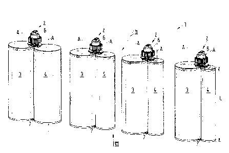
Fig. 1 shows in a perspective representation an embodiment of a set of
multicomponent cartridges in accordance with the invention which is
designated as a whole by the reference numeral 1 and here includes four
multicomponent cartridge 2.
In the following, reference is made with exemplary character to the
application particularly relevant to practice that the multicomponent
cartridges 2 are each two-component cartridges 2. It is, however,
understood that the invention is not restricted to such embodiments, but
can also include in accordingly the same manner multicomponent
cartridges 2 for more than two components.
Fig. 2 shows the set 1 of Fig. 1 in a view from the direction of gaze shown
by the arrow II in Fig. 1.
CA 02838293 2013-12-04
9
Fig. 3 shows a view of the base of the multicomponent cartridges 2, that is
a view from the direction of gaze shown by the arrow III in Fig. 3.
For better understanding, Fig. 4 shows one of the multicomponent
cartridges 2 in a longitudinal section representation along the longitudinal
direction A.
Each of the two-component cartridges 2 includes a first reception chamber
3 for a first component and a second reception chamber 4 for the second
component. Each of the reception chambers 3, 4 is substantially
cylindrical in design and extends in a longitudinal direction A which
corresponds to the cylinder axis. The two-component cartridges 2 of the
set 1 are so-called side-by-side cartridges, that is the two reception
chambers 3, 4 of the two-component cartridges 2 are arranged next to one
another so that their cylinder axes, which each extend in the direction of
the longitudinal direction A, are parallel to one another. The length L of
the first reception chamber 3 is the same as the length L of the second
reception chamber 4, with the extent of the respective reception chamber
3, 4 in the longitudinal direction A being meant by the length L.
It is admittedly preferred, but not necessarily the case, that the length L is
always the same for all multicomponent cartridges 2 of the set 1. The two
reception chambers 3, 4 admittedly always have the same length L in each
multicomponent cartridge 2, but it is by all means possible that this
length L is different for different multicomponent cartridges 2 of the same
set 1.
The first and the second reception chambers 3 and 4 respectively have a
separate outlet 31 and 41 respectively (see Fig. 4) which is in each case
provided in the end surface of the cylindrical reception chamber 3, 4 at
CA 02838293 2013-12-04
=
the top in accordance with the representation and by which the respective
component can be dispensed from the reception chamber. Each outlet 31,
41 has a circular cross-section and is designed in passage form.
5 Each two-component cartridge 2 has a common connector piece 5 which
connects the two end faces of the reception chambers with the outlets 31,
41. The outlets 31 and 41 are arranged in this connector piece 5. The
common connector piece 5 is designed for the cooperation with an
accessory part.
In the embodiment described her, each multicomponent cartridge is
shown with a closure cap 6 which cooperates with the connection part 5.
The closure cap 6 has two spigots 61 of which each engages into one of
the two outlets 31, 41 to close them. The closure cap 6 has a screw
connection 62 which cooperates with a thread of the connector piece 5.
Each of the two-component cartridges 2 is manufactured in one piece so
that their reception chambers 3, 4 are each non-releasably connected to
one another, that is the two reception chambers 3, 4 cannot be separated
from one another in a non-destructive manner. The two storage chambers
3, 4 are connected to one another via a plurality of parts, namely by the
common connector piece 5 at its end face having the outlets 31, 41, by a
connector bar 7 (see Fig. 3) at the end of the reception chambers 3, 4
remote from the outlets and by a plurality of intermediate bars 8 (see Fig.
4) which connect the cylindrical walls of the reception chambers 3, 4 to
one another at different levels with respect to the longitudinal direction A.
Each two-component cartridge 2 is preferably manufactured in an
injection molding process. Since the two-component cartridges 2 are in
CA 02838293 2013-12-04
=
=
11 =
one piece, they can be manufactured in a simple and inexpensive manner
in a single-stage injection molding process.
The multicomponent cartridges 2 are composed of plastic, with all plastics
usually used for cartridges being suitable, for example polyamide (PA),
polypropylene (PP), polyethylene (PE), polybutylene terephthalat (PBT) or
polyolefins in general.
As can in particular be recognized in Figs. 3 and 4, the two-component
cartridges 2 are each shown with an inserted piston 9 in each reception
chamber 3, 4. This piston 9 is manufactured separately from the two-
component cartridge 2 and is usually only inserted after the filling of the
reception chambers 3, 4. The two-component cartridges 2 are therefore
first manufactured in an injection molding process and then closed, for
example, using the closure cap 6 at the outlets 31, 41. The respective
components are then filled into the first or second reception chamber 3
and 4 respectively from the still open end of the reception chambers 3, 4
at the bottom in the illustration. Subsequently, a respective piston 9 is
inserted into the reception chamber 3 and 4 respectively, said piston then
forming the respective chamber base and sealingly closing the reception
chamber 3, 4. The pistons 9 are frequently designed as valve pistons so
that, on the insertion of the pistons 9, the air which may be present
between the component and the piston can be removed in a simple
manner.
To use the two-component cartridge 2, it is usually inserted into the
holder of a dispensing apparatus (dispenser). The closure cap 6 is
removed, unscrewed here, and a mixer is fastened to the common
connector piece in its place, here therefore with a screw connection. This
mixer is frequently a static mixer known per se which then has two
CA 02838293 2013-12-04
=
12
separate inlets which each form a flow connection with one of the outlets
31, 41 so that the respective component moves from the reception
chamber 3 and 4 respectively through the outlet 31 and 41 respectively
into the mixer. The two components meet one another here and are mixed
intimately with one another on passing through the mixer.
For dispensing the components, the dispensing apparatus usually has a
double plunger or two individual plungers which apply pressure to the two
pistons 9 in the first and second reception chambers 3 and 4 respectively,
as is indicated in Fig. 4 by the two arrows with the reference symbol P.
The two pistons 9 simultaneously slide upward in accordance with the
presentation along the inner wall of the first or second reception chambers
3 and 4 respectively due to the application of pressure, whereby the
respective components are dispensed into the mixer. After ending the
application, the mixer can be removed again and can be replaced by the
closure cap 6.
The connection of the common connection piece 5 to the closure cap 6 or
to the mixer can naturally also take place in another manner than by a
screw connection, for example by means of a bayonet connection. The
connection piece 5 has a bayonet coupling in a manner known per se
which cooperates with a bayonet coupling provided at the closure cap 6 or
at the mixer or at another accessory part such that the two parts are
reliably connected to one another.
The set 1 of multicomponent cartridges 2 in accordance with the invention
is in particular characterized in that in each of the at least two
multicomponent cartridges 2, the first reception chamber 3 has the same
outer diameter Dl. It can be realized by this measure that all
multicomponent cartridges 2 of the set 1 can be inserted into the same
CA 02838293 2013-12-04
13
dispensing device. Since namely the multicomponent cartridges 2 are in
one piece, the two reception chambers 3 and 4 respectively are rigidly
connected to one another - here by the connector piece 5, the connection
bar 7 and the intermediate bars 8 - it is sufficient that the holder in the
dispensing device is designed so that it receives the first reception
chamber 3 reliably and firmly. The outer diameter D2 of the second
reception chamber 4 can then vary without the secure and reliable
dispensing function being endangered thereby.
It is preferred for technical manufacturing reasons that every first
reception chamber 3 of a set 1 has the same volume. With the same length
L, this means that the wall thickness d of the wall of the first reception
chamber 3 is the same for all multicomponent cartridges 2 of the set 1. It
is, however, also possible and optionally desirable for some applications
that the wall thickness d of the wall of the first reception chamber 3 has
different values for two different multicomponent cartridges 2 which
belong to the same set 1.
If all first reception chambers 3 have the same wall thickness d, they also
have the same inner diameter. This is particularly advantageous because
then the same piston 9 can be used for all the first reception chambers 3;
no pistons 9 with different diameters therefore then have to be provided
for the first reception chambers 3.
It is thus possible by the variation of the outer diameter D2 of the second
reception chamber 4 to realize different mixing ratios for the two
components. In this respect, what is meant by the mixing ratio is how
many parts of the first component there are to one part of the second
component. A mixing ratio of 2:1 means, for example, that there are two
CA 02838293 2013-12-04
14
parts of the first component to one part of the second component, with
volume parts being meant by parts here.
Since the two reception chambers 3, 4 of the two-component cartridges 2
are of equal length and the two pistons 9 are usually pushed forward
synchronously and in parallel on the dispensing of the two components,
the mixing ratio can be set via the diameter D2 of the second reception
chamber 4. The mixing ratio is then given by the ratio of the two circular
cross-sectional surfaces of the two reception chambers 3, 4 in each case
perpendicular to the longitudinal direction A. If the wall thicknesses d of
the first and second reception chambers 3 and 4 respectively are the same
- which is as a rule the case - the mixing ratio is defined by the ratio of
the
outer diameter D1 of the first reception chamber 3 to the outer diameter
D2 of the second reception chamber 4. This statement also applies at least
approximately with an unequal wall thickness d of the two reception
chambers 3, 4.
In the set 1 shown in Fig. 1, the following mixing ratios are realized in the
four two-component cartridges 2 from left to right in accordance with the
illustration: 1:1; 2:1; 3:1; and 4:1.
The order in Figs. 2 and 3 is exactly the opposite due to the direction of
gaze. The respective multicomponent cartridge 2 at the extreme left in
accordance with the illustration here has the mixing ratio 4:1; the mixing
ratios 3:1; 2:1 and 1:1 follow to the right.
The multicomponent cartridge 2 shown in section in Fig. 4 has the mixing
ratio 2:1
CA 02838293 2013-12-04
,
15 '
Since the cross-sectional areas of the reception chambers 3, 4
perpendicular to the longitudinal direction A are circular areas in each
case, the ratio of the outer diameter D1 of the first reception chamber 3 to
the outer diameter D2 of the second reception chamber 4 has the value 2
for the mixing ration 4:1; the value square root of three for the mixing
ratio 3:1; and the value square root of 2 for the mixing ratio 2:1. The outer
diameter D1 of the first reception chamber 3 is equal to the outer diameter
D2 of the second reception chamber 4 for the mixing ratio 1:1.
It is naturally understood that the set 1 of multicomponent cartridges 2
can alternatively or additionally also include further multicomponent
cartridges 2 with different mixing ratios.