Language selection

Search

Patent 2838370 Summary

Third-party information liability

Some of the information on this Web page has been provided by external sources. The Government of Canada is not responsible for the accuracy, reliability or currency of the information supplied by external sources. Users wishing to rely upon this information should consult directly with the source of the information. Content provided by external sources is not subject to official languages, privacy and accessibility requirements.

Claims and Abstract availability

Any discrepancies in the text and image of the Claims and Abstract are due to differing posting times. Text of the Claims and Abstract are posted:

  • At the time the application is open to public inspection;
  • At the time of issue of the patent (grant).
(12) Patent: (11) CA 2838370
(54) English Title: LEFT AND RIGHT SIDE VIEW MIRRORS
(54) French Title: MIROIRS LATERAUX GAUCHE ET DROIT
Status: Expired and beyond the Period of Reversal
Bibliographic Data
(51) International Patent Classification (IPC):
  • B60R 1/04 (2006.01)
  • B62D 63/04 (2006.01)
(72) Inventors :
  • DAUPHINEE, THOMAS M. (Canada)
(73) Owners :
  • THOMAS M. DAUPHINEE
(71) Applicants :
  • THOMAS M. DAUPHINEE (Canada)
(74) Agent: GEORGE A. ROLSTONROLSTON, GEORGE A.
(74) Associate agent:
(45) Issued: 2016-09-20
(22) Filed Date: 2013-12-30
(41) Open to Public Inspection: 2014-08-20
Examination requested: 2014-10-17
Availability of licence: N/A
Dedicated to the Public: N/A
(25) Language of filing: English

Patent Cooperation Treaty (PCT): No

(30) Application Priority Data:
Application No. Country/Territory Date
13/998,283 (United States of America) 2013-10-18
61/850,613 (United States of America) 2013-02-20

Abstracts

English Abstract


Left and Right side view mirrors for a vehicle giving the driver a view
outwardly to each
side of the vehicle, to check lanes on each side, to ensure safe lane changes
, separate
mounting devices for the two mirrors, a diagonal line across the left mirror,
and a
diagonal line across the right mirror, the diagonal lines slanting downwardly
towards the
outside edge of each mirror,, and an upper edge line on each mirror parallel
to the
upper edge of each mirror. .


French Abstract

Miroirs latéraux gauche et droit, conçus pour un véhicule, offrant au conducteur une vue vers lextérieur, vers chaque côté du véhicule. Les miroirs permettent de vérifier les voies de chaque côté, de veiller à effectuer des changements de voie sécuritaires. Linvention présente des dispositifs de fixation séparés pour les deux miroirs, une ligne diagonale dans le miroir de gauche et une ligne diagonale dans le miroir de droite, les lignes diagonales étant inclinées vers le bas, vers lextrémité externe de chaque miroir. De plus, une ligne dextrémité supérieure sur chaque miroir est parallèle à lextrémité supérieure de chaque miroir.

Claims

Note: Claims are shown in the official language in which they were submitted.

THE EMBODIMENTS OF THE INVENTION IN WHICH AN EXCLUSIVE PROPERTY
OR PRIVILEGE IS SOUGHT ARE DEFINED AS FOLLOWS;
1. A pair of left and right side view mirrors for a vehicle and
comprising:;
a left side view planar mirror for a vehicle giving a driver a view outwardly
to the left of
the vehicle to check the adjacent left lanes;
a right side view planar mirror for the vehicle giving the driver a view
outwardly on the
right side of the vehicle to check the adjacent right lanes;
each said mirror defining an upper edge and two side edges;
a diagonal line across said left side planar mirror extending from right to
left at a
downward angle on said left mirror;
a diagonal line across said right side planar mirror extending from the left
hand edge of
the right hand mirror at a downward angle towards the right hand edge of the
right
mirror;
an upper edge line on the right mirror extending parallel to the upper edge of
said right
mirror and a further upper edge line extending parallel to the upper edge of
said left
mirror; and,
a mounting device for the left mirror and a separate mounting device for the
right mirror,
mounting respective mirrors on the left and right hand sides of the windshield
of a
vehicle, the mounting devices permitting rotation and tilting of each said
mirror to
enable viewing of left and right hand lanes respectively, thereby enabling
safe lane
changes.

2. The pair of side view mirrors for a vehicle as claimed in claim 1 and
including a
right hand edge line on said left mirror extending parallel to the right hand
edge of said
left mirror, and a left hand edge line on said right mirror extending parallel
to said left
hand edge of said right mirror.
3. The pair of side view mirrors for a vehicle as claimed in claim 2 wherein
said left
side view mirror has a predetermined cross sectional area and wherein said
right side
view mirror has a cross sectional area between 90% and 100% greater than said
left
side view mirror.
4. The pair of side view mirrors for a vehicle as claimed in claim 3
wherein said left
side view mirror and said right side view mirror are of rectangular shape, and
wherein
each define longer side edges and shorter end edges.
5. The pair of side view mirrors for a vehicle as claimed in claim 4
wherein the
proportions between the length and height of each said mirror are
between 5:1 and 6:1.

Description

Note: Descriptions are shown in the official language in which they were submitted.


CA 02838370 2013-12-30
FIELD OF THE INVENTION
The invention relates to side view mirrors for a vehicle, and in particular to
a pair of left
and right side view mirrors giving the driver a view outwardly to each side of
the vehicle,
to check lanes on each side, and to ensure safe lane changes.
BACKGROUND OF THE INVENTION.
When making a lane change, especially on a highway with multiple lanes, it is
necessary for the driver to ensure that there is no other vehicle, in an
adjacent lane.
Various proposals have been made in the past for mirrors providing all round
view, from
e centre of the driving compartment. However these mirrors are not totally
effective to
provide a view of vehicles which may be in an adjacent side lane, either to
the left or to
the right. In addition, these centre view mirrors involve modifying the
interior of the car
substantially to remove the existing rear view mirror and replace it with some
more
complex structure. In addition, the costs of such all round mirrors have been
a factor
detracting from their appeal.
Clearly it is desirable to provide some form of effective side view mirrors
which are both
economical to manufacture and which can easily be installed by the driver of
the
vehicle, and most importantly provide a means of monitoring the presence of
vehicles in
lanes on either side, which would otherwise require a twisting movement of the
head to
BRIEF DESCRIPTION OF THE INVENTION
A left side mirror is located near the top of the left side of the windshield
with the right
hand edge in front the driver. A right side mirror is located near the top of
the right side
1

CA 02838370 2013-12-30
of the windshield with its left hand edge in front of the front seat
passenger. For
simplicity, the mirrors may be suction cup mounted on pivot bases. The mirrors
are
adjustable in the same way that the centre rear view mirror is adjusted, ie.
They can be
rc,tated at angles and tilted down.
A black line is located across the top of each mirror sloping at an angle.
A further black line is located along the top of each mirror, parallel to the
top edge, and
a further black line is located along the right hand vertical edge of the left
side mirror
and along the left hand vertical edge of the right side mirror, for reasons to
be described
below.
The various features of novelty which characterize the invention are pointed
out with more
particularity in the claims annexed to and forming a part of this disclosure.
For a better
understanding of the invention, its operating advantages and specific objects
attained by its
use, reference should be made to the accompanying drawings and descriptive
matter in
wnich there are illustrated and described preferred embodiments of the
invention.
IN THE DRAWINGS
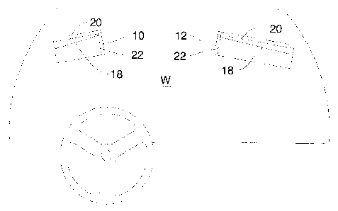
Figure 1 is an elevation of a car interior illustrating the left and right
side view mirrors, of the
nyention;
Figures 2 and 3 show the proportions of the left and right side view mirrors;
Figure 4 is a schematic illustration showing the lines of sight of the driver,
available to the
driver, using the left and right side mirrors.
DESCRIPTION OF A SPECIFIC EMBODIMENT
As noted above the invention provides two separate mirrors, namely a left side
mirror (10)
and a right side mirror (12). In this example, each of the mirrors are mounted
on a suction
2

CA 02838370 2013-12-30
=
cup base (14) (Fig 1) provided with a typical adjustable ball joint or swivel
mount (16).
The left and right side mirrors are located on left and right sides of a
windshield (W).
The left side mirror is smaller and the right side mirror is larger. Both
mirrors are
elongated, and of a relatively reduced height. Preferably the left and right
mirrors will
h:ye proportions between the length and the height of between 5 - to1 and 6 to
1.
Preferably the left side mirror will define somewhere about 70 - 90 sq. cm.,
and the right
side mirror will define somewhere between about 140- 160 sq. cm.
The proportion between the two mirrors is somewhere in the region of the right
side mirror
area being between about 90 -110 percent larger than the area of the left side
mirror. In
the embodiment illustrated, a 20cm x 4cm(approx.) left side mirror (10) is
located near the
left side of the top of the windshield (W) with the right hand mirror edge in
front the driver.
R 30cm x 5 cm approx. right side mirror (12) is located near the top of the
right side of the
windshield with its left hand mirror edge in front of the front seat
passenger. In this
example, the mirrors are suction cup mounted on pivot bases (14) and are
adjustable in
the same way that the usual centre rear view mirror is adjusted.
While suction cups are particularly suitable for sale of mirrors in the
automobile after
market, it is of course possible that such side view mirrors will be adopted
by one or more
anufacturers in which case they would be attached by the usual adhesive or
other
methods, such as in use for the attachment of the centre rear view mirrors.
A black line (18) is located near the top of each mirror running from 4mm down
from the
upper edge at the inner end to 16mm down at the outer edge on the driver side
left mirror
(10) and 6mm to 24mm on the passenger side right mirror (12).
An upper edge black line (20) is located along the top edge of each mirror,
parallel to the
3

CA 02838370 2013-12-30
top edge of the mirror, and spaced downwardly two or three millimetres.
A side edge black line (22) is located on each mirror. Line (22) on the left
side mirror (10)
being located parallel to and spaced inwardly from the right hand edge of the
left side
mirror, and the black line (22) on the right side mirror being spaced adjacent
to and
inwardly from the left hand vertical edge of the right side mirror.
The purposes of the lines (20) and (22) is to provide the driver with an
indication that
either a vehicle is approaching and presenting a possible lane change hazzard.
In the
alternative, when a vehicle in an adjacent lane moves over the sloping line
(18) or past the
eurLical clack line (22) it indicates that a lane change can be made safely.
The driver side left mirror (10) is adjusted so that the driver can just see
the back post of
the driver side rear door on the right side of that mirror. The field
of view will include a
substantial area to the left of the car. The passenger side right mirror (12)
is adjusted so
that the driver can just see the back post of the passenger side rear door on
the left side
of that mirror. The field of view will include a substantial area to the right
of the car. Both
mirrors are adjusted and tilted in such a way that the black line (18) on the
mirror lies on
the image of the lane marking line on the far side of the adjacent lane. The
top of the
mirror will then correspond to about 1.5 m beyond that line.
All mirror adjustments should be made with one eye closed, right eye closed
for the
ivers sioc- mirror and left eye for the passenger side.
A vehicle in the adjacent lane will fill the mirror from top to bottom. Once
set, most drivers
will be able, in most cases, to use the mirrors without further adjustment and
without eye
o,osure. With eye closure, the lowest parts of the wheels of a vehicle in the
next lane will
normally be visible above black line (18) on the mirror. If they are not above
blackline
4

CA 02838370 2013-12-30
(18), the car is encroaching into the adjacent lane and no lane change should
be
attempted.
The lowest parts of the wheels of a vehicle in the next lane over may be
visible at the top
of the mirror.
On both sides of the car, the driver can see in the appropriate mirror or in
the front door window
or the windshield, at least part of any vehicle in a position such that he/she
should not move
into that vehicle's lane. A shoulder check, which is inconvenient (and nearly
impossible for
people with limited head motion) is no longer required.
Alternatively, if the top edge of the mirror is located on the image of the
far side lane marking,
u no part of the next lane will be visible in the mirror with eye closure.
However, there is an
advantage to seeing the lower parts of vehicles in the far lane, as a warning
that they could be
about to move over.
V.'nen passing another vehicle on either side, that vehicle will be seen first
through the
windshield, then through the front door window, and, while still in view in
the front door
window will appear at the outer edge of the side-view mirror and will progress
across the
r:.irror to the inner edge and finally out of view. At this "safe point" it is
safe to move over
into that vehicle's lane with several car lengths (depending on lane width and
location in
the lanes) safety margin between the two cars. In city driving at low speed,
the safe point
occurs after the car falls behind black line (22).
I-ne driver side mirror (10) is smaller for the same width of view because the
eye-to-mirror
distance is less. There is no reduction of image size on either side.
Deviations from the settings of the mirrors as described to suit personal
preferences will
...A seriously affect performance. Using suction cup mountings near the top of
the

CA 02838370 2013-12-30
.,.:ndshield, the mirrors can be installed in a few minutes.
As mentioned above, the use of suction cup mountings is particularly suitable
for the
automotive after market. However if the mirrors are adopted by an automobile
manufacturer,
it is in all I,kely that the side view mirrors (10 and 12) will be attached by
the usual permanent
adhesive such as is used for attaching the centre rear view mirror at the
present time.
The foregoing is a description of a preferred embodiment of the invention
which is given here
by way of example only. The invention is not to be taken as limited to any of
the specific
ieatures as described, but comprehends all such variations thereof as come
within the scope
of the appended claims.
6

Representative Drawing
A single figure which represents the drawing illustrating the invention.
Administrative Status

2024-08-01:As part of the Next Generation Patents (NGP) transition, the Canadian Patents Database (CPD) now contains a more detailed Event History, which replicates the Event Log of our new back-office solution.

Please note that "Inactive:" events refers to events no longer in use in our new back-office solution.

For a clearer understanding of the status of the application/patent presented on this page, the site Disclaimer , as well as the definitions for Patent , Event History , Maintenance Fee  and Payment History  should be consulted.

Event History

Description Date
Time Limit for Reversal Expired 2018-12-31
Letter Sent 2018-01-02
Maintenance Request Received 2016-09-22
Grant by Issuance 2016-09-20
Inactive: Cover page published 2016-09-19
Inactive: Final fee received 2016-07-27
Pre-grant 2016-07-27
Notice of Allowance is Issued 2016-05-26
Letter Sent 2016-05-26
Notice of Allowance is Issued 2016-05-26
Inactive: Approved for allowance (AFA) 2016-05-18
Inactive: Q2 passed 2016-05-18
Amendment Received - Voluntary Amendment 2016-01-07
Inactive: S.30(2) Rules - Examiner requisition 2015-10-29
Inactive: Report - No QC 2015-10-25
Maintenance Request Received 2015-10-23
Letter Sent 2014-10-30
Request for Examination Requirements Determined Compliant 2014-10-17
All Requirements for Examination Determined Compliant 2014-10-17
Request for Examination Received 2014-10-17
Inactive: Cover page published 2014-09-15
Application Published (Open to Public Inspection) 2014-08-20
Inactive: IPC assigned 2014-03-25
Inactive: First IPC assigned 2014-03-25
Inactive: IPC assigned 2014-03-24
Inactive: Filing certificate - No RFE (bilingual) 2014-01-20
Filing Requirements Determined Compliant 2014-01-20
Application Received - Regular National 2014-01-14
Small Entity Declaration Determined Compliant 2013-12-30
Inactive: Pre-classification 2013-12-30

Abandonment History

There is no abandonment history.

Maintenance Fee

The last payment was received on 2015-10-23

Note : If the full payment has not been received on or before the date indicated, a further fee may be required which may be one of the following

  • the reinstatement fee;
  • the late payment fee; or
  • additional fee to reverse deemed expiry.

Please refer to the CIPO Patent Fees web page to see all current fee amounts.

Fee History

Fee Type Anniversary Year Due Date Paid Date
Application fee - small 2013-12-30
Request for examination - small 2014-10-17
MF (application, 2nd anniv.) - small 02 2015-12-30 2015-10-23
Final fee - small 2016-07-27
MF (patent, 3rd anniv.) - small 2016-12-30 2016-09-22
Owners on Record

Note: Records showing the ownership history in alphabetical order.

Current Owners on Record
THOMAS M. DAUPHINEE
Past Owners on Record
None
Past Owners that do not appear in the "Owners on Record" listing will appear in other documentation within the application.
Documents

To view selected files, please enter reCAPTCHA code :


To view images, click a link in the Document Description column. To download the documents, select one or more checkboxes in the first column and then click the "Download Selected in PDF format (Zip Archive)" or the "Download Selected as Single PDF" button.

List of published and non-published patent-specific documents on the CPD .

If you have any difficulty accessing content, you can call the Client Service Centre at 1-866-997-1936 or send them an e-mail at CIPO Client Service Centre.


Document
Description 
Date
(yyyy-mm-dd) 
Number of pages   Size of Image (KB) 
Description 2013-12-30 6 227
Abstract 2013-12-30 1 6
Drawings 2013-12-30 3 30
Claims 2013-12-30 2 56
Representative drawing 2014-07-25 1 7
Cover Page 2014-09-15 1 28
Abstract 2016-01-07 1 14
Claims 2016-01-07 2 60
Cover Page 2016-08-19 1 32
Filing Certificate 2014-01-20 1 179
Acknowledgement of Request for Examination 2014-10-30 1 176
Maintenance Fee Notice 2018-02-13 1 183
Maintenance Fee Notice 2018-02-13 1 184
Reminder of maintenance fee due 2015-09-01 1 112
Commissioner's Notice - Application Found Allowable 2016-05-26 1 163
Examiner Requisition 2015-10-29 3 226
Maintenance fee payment 2015-10-23 1 33
Amendment / response to report 2016-01-07 5 120
Final fee 2016-07-27 1 26
Maintenance fee payment 2016-09-22 1 28