Note: Descriptions are shown in the official language in which they were submitted.
CA 02838613 2015-06-16
1
REPLACEMENT SPECIFICATION
ANTENNA MODULE HAVING INTEGRATED RADIO FREQUENCY CIRCUITRY
CROSS-REFERENCE TO RELATED APPLICATIONS
[0001] This application claims the benefit of United States Provisional Patent
Application Serial No. 61/495,235, filed on June 9, 2011.
BACKGROUND
[0002] United States Patent No. 7,079,869, issued July 18, 2006, and titled
"COMMUNICATION SYSTEM TRANSMITTER OR RECEIVER MODULE HAVING
INTEGRATED RADIO FREQUENCY CIRCUITRY DIRECTLY COUPLED TO ANTENNA
ELEMENT" (also referred to here as the "869 Patent") describes a radio
frequency
(RF) module that comprises integrated RF circuitry comprising at least one of
a
transmitter and a receiver, and an antenna element operatively coupled to the
integrated RF circuitry.
[0003] The antenna element comprises first and second substantially co-planar
portions, each of said first and second substantially co-planar portions
having an
inner end and an outer end. The first and second substantially co-planar
portions
are arranged end-to-end with their respective inner ends proximate one
another.
The integrated RF circuitry is disposed substantially adjacent the respective
inner
ends of the first and second substantially co-planar portions of the antenna
element.
[0004] However, the configuration of this module may not be suitable for all
applications.
SUMMARY
[0005] One embodiment is directed to an antenna module comprising integrated
RF
circuitry comprising at least one of a transmitter and a receiver. The module
further
comprises an antenna element operatively coupled to the integrated RF
circuitry, the
CA 02838613 2013-12-05
WO 2012/170865 2
PCT/US2012/041630
antenna element comprising first and second substantially co-planar portions.
The
integrated RF circuitry is disposed on an interior part of at least one of the
first and
second substantially co-planar portions.
[0006] Another embodiment is directed to an antenna module comprising
integrated RF circuitry comprising at least one of a transmitter and a
receiver. The
module further comprises an antenna element operatively coupled to the
integrated
RF circuitry, the antenna element comprising first and second substantially co-
planar
portions. Each of the first and second substantially co-planar portions has a
first end
and a second end. The integrated RF circuitry is disposed substantially
adjacent to a
region of the first substantially co-planar portion of the antenna element
that does
not include the respective first end of the first substantially co-planar
portion of the
antenna element.
[0007] Another embodiment is directed to an antenna module comprising a radio
frequency transmitter, a radio frequency receiver, and an antenna element
operatively coupled to the radio frequency transmitter and radio frequency
receiver.
The antenna element comprises first and second substantially co-planar
portions.
The radio frequency transmitter is operatively coupled to the first
substantially co-
planar portion of the antenna element. The radio frequency receiver is
operatively
coupled to the second substantially co-planar portion of the antenna element.
Each
of the first and second substantially co-planar portions have a first end and
a second
end. The first and second substantially co-planar portions are arranged end-to-
end
with their respective first ends substantially separated from one another
within the
antenna module.
[0008] Another embodiment is directed to an antenna module comprising
integrated RF circuitry comprising at least one of a transmitter and a
receiver. The
module further comprises an antenna element operatively coupled to the
integrated
RF circuitry, the antenna element comprising first and second substantially co-
planar
portions. Each of the first and second substantially co-planar portions has a
first end
SUBSTITUTE SHEET (RULE 26)
CA 02838613 2013-12-05
WO 2012/170865 3
PCT/US2012/041630
and a second end. The first and second substantially co-planar portions are
arranged
with their respective first ends proximate one another and offset from one
another.
The integrated RF circuitry is disposed substantially adjacent the respective
first ends
of the first and second substantially co-planar portions of the antenna
element.
[0009] Another embodiment is directed to a radio frequency (RF) module for use
in
a communication device of a communication system. The module comprises
integrated RF circuitry comprising at least one of a transmitter and a
receiver. The
module further comprises an antenna element operatively coupled to the
integrated
RF circuitry. The antenna element comprises first and second planar portions.
The
first planar portion is disposed in a first plane and the second planar
portion is
disposed in a second plane. Each of the first and second planar portions has a
respective first end and a respective second end. The first and second planar
portions are arranged within the respective first and second planes end-to-end
with
their respective first ends proximate one another. The integrated RF circuitry
is
disposed substantially adjacent the respective first ends of the first and
second
planar portions of the antenna element.
DRAWINGS
[0010] FIG. 1 is a block diagram of one exemplary embodiment of an integrated
antenna module.
[0011] FIGS. 2-4 are diagrams illustrating examples of patch antennas.
[0012] FIG. 5 illustrates one exemplary embodiment of an integrated antenna
module with two transmit antenna portions and two receive antenna portions.
[0013] FIG. 6 illustrates one example of a circular patch antenna.
[0014] FIGS. 7-13 illustrate various embodiments of antenna elements.
SUBSTITUTE SHEET (RULE 26)
CA 02838613 2013-12-05
WO 2012/170865 4
PCT/US2012/041630
[0015] FIG. 14 is a block diagram of one exemplary embodiment of a distributed
antenna system in which integrated antenna modules can be used.
DETAILED DESCRIPTION
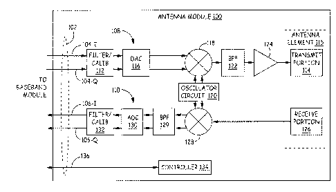
[0016] FIG. 1 is a block diagram of one exemplary embodiment of an integrated
antenna module 100. The exemplary embodiment of the integrated antenna
module 100 shown in FIG. 1 communicates with a digital baseband module (not
shown) using a digital baseband interface 102. Examples of suitable digital
baseband interfaces include the digital baseband interfaces specified in the
Open
Base Station Architecture Initiative (OBSAI) and Common Public Radio Interface
(CPRI) family of standards and specifications. The digital baseband interface
102
provides an interface by which digital "transmit" baseband data 104 is
provided to
the antenna module 100 from the digital baseband module and by which digital
"receive" baseband data 106 is provided from the antenna module 100 to the
digital
baseband module. In the particular exemplary embodiment described here in
connection with FIG. 1, the digital transmit baseband data 104 comprises an in
phase
component 104-land a quadrature-phase component 104-Q, and the digital receive
baseband data 106 comprises an in-phase component 106-land a quadrature-phase
component 106-Q.
[0017] The integrated antenna unit 100 is implemented using integrated RF
circuitry.
The integrated RF circuitry includes a transmit path 108 (also referred to
here as a
"transmitter" 108) and a receive path 110 (also referred to here as the
"receiver"
110).
[0018] The transmitter 108 includes a digital filter/calibration unit 112 that
applies
phase and/or amplitude changes to the digital transmit baseband data 104
received
over the digital baseband interface 102. These applied phase and/or amplitude
changes are used to create a defined phase and/or amplitude relationship
between
various RF signals radiated from the transmit portion 114 of an antenna
element 115
of multiple antenna modules 100 in an antenna array (described below) in order
to
SUBSTITUTE SHEET (RULE 26)
CA 02838613 2013-12-05
WO 2012/170865 5
PCT/US2012/041630
perform beam forming and/or antenna steering. The digital filter/calibration
unit
112 is also configured to calibrate the transmit path 108. Calibrating the
transmit
path 108 involves one or more of estimating the accumulated phase and/or
amplitude deviation along the transmit path 108 and the time it takes a signal
to
travel from the digital baseband interface 102 to the respective transmit
portion 114
of the antenna element 115 (described below). The digital filter/calibration
unit 112
is also configured to apply digital pre-distortion to the digital transmit
baseband data
104 in order to compensate for non-linearities in the transmit path 108. In
the
particular exemplary embodiment described here in connection with FIG. 1, the
digital filter/calibration unit 112 operates on both the in-phase and
quadrature
components 104-land 104-Q of the digital transmit baseband data 104. The
digital
output of the digital filter/calibration unit 112 includes both in-phase and
quadrature
components.
[0019] In the particular exemplary embodiment described here in connection
with
FIG. 1, the transmit path 108 of the antenna module 100 also includes a
digital-to-
analog converter (DAC) 116 that converts the in-phase and quadrature
components
of the digital output of the digital filter/calibration unit 112 to respective
analog
baseband in-phase and quadrature signals. The transmit path 108 of the antenna
module 100 also includes quadrature mixer 118 that mixes the analog baseband
in-
phase and quadrature signals output by the DAC 116 with appropriate quadrature
mixing signals to produce the desired transmit RF signal. The quadrature
mixing
signals are produced in the conventional manner by an oscillator circuit 120.
The
oscillator circuit 120 is configured to phase lock a local clock signal to a
reference
clock and to produce the mixing signals at the desired frequency. The RF
transmit
signal output by the quadrature mixer 118 is bandpass filtered by bandpass
filter 122
and amplified by amplifier 124.
[0020] The transmitter 108 is coupled to the transmit portion 114 of the
antenna
element 115 in order cause the RF transmit signal output by the transmitter
108 to
be radiated from the transmit antenna element 114. In the embodiment shown in
SUBSTITUTE SHEET (RULE 26)
CA 02838613 2013-12-05
WO 2012/170865 6
PCT/US2012/041630
FIG. 1, the antenna element 115 that is coupled to integrated RF circuitry
(that is, the
transmitter 108 and receiver 110) includes a transmit portion 114 and a
receive
portion 126, where the transmitter 108 is coupled to the transmit portion 114
and
the receiver 110 is coupled to the receive portion 126. In general, the
antenna
element 115 (and the portions 114 and 126 thereof) can be configured as
described
in the '869 Patent with the modifications and improvements described here.
[0021] The receiver 110 is coupled to the receive portion 126 of the antenna
element 115 in order to receive an analog RF receive signal. In the particular
exemplary embodiment described here in connection with FIG. 1, the analog RF
receive signal is input to a quadrature mixer 128 that mixes the analog RF
receive
signal with appropriate quadrature mixing signals in order to produce analog
baseband in-phase and quadrature signals. The quadrature mixing signals are
produced by the oscillator circuit 120. The analog baseband in-phase and
quadrature signals output by the quadrature mixer 128 are bandpass filtered by
bandpass filters 129.
[0022] In the particular exemplary embodiment described here in connection
with
FIG. 1, the receiver 110 also includes an analog-to-digital converter (ADC)
130 that
converts the analog baseband in-phase and quadrature signals to in-phase and
quadrature digital receive baseband data, respectively.
[0023] The receiver 110 also includes a digital filter/calibration unit 132
that applies
phase and/or amplitude changes to the digital receiver baseband data output by
the
ADC 130. These applied phase and/or amplitude changes are used to create a
defined phase and/or amplitude relationship between various RF signals
received
from the receive portion 126 of the antenna element 115 of multiple antenna
modules 100 in an antenna array (described below) in order to perform beam
forming and/or antenna steering. The digital filter/calibration unit 132 is
also
configured to calibrate the receive path 110. Calibrating the receive path 110
involves one or more of estimating the accumulated phase and/or amplitude
SUBSTITUTE SHEET (RULE 26)
CA 02838613 2013-12-05
WO 2012/170865 7
PCT/US2012/041630
deviation along the receive path 110 and the time it takes a signal to travel
from the
respective receive portion 126 (described below) to the digital baseband
interface
102. The digital filter/calibration unit 132 is configured to apply digital
post-
distortion to the digital receive baseband data in order to compensate for non-
linearities in the receive path 110. In the particular exemplary embodiment
described here in connection with FIG. 1, the digital filter/calibration unit
132
operates on both the in phase and quadrature components of the digital receive
baseband data output by the ADC 130. The digital output of the digital
filter/calibration unit 132 is the digital receive baseband data 106 that is
provided to
the baseband module over the digital baseband interface 102.
[0024] Multiple antenna modules 100 can be arranged together in order to form
an
antenna array that can be used to perform beam forming and/or antenna steering
(for example, as described in the '869 Patent).
[0025] Each antenna module 100 also includes a controller 134 (or other
programmable processor) that is used to control the operation of the antenna
module 100 and to interact with the baseband module using a control interface
136
implemented between the antenna module 100 and the baseband module.
[0026] In the embodiment shown in FIG. 1, separate transmit and receive
portions
114 and 126 of the antenna element 115 are used in order to reduce the amount
of
filtering required between transmit path 108 and the receive path 110. Doing
so
reduces the cost of the antenna module 100. Typically, a duplexer is required
between the transmit path and the receive path in a frequency division duplex
(FDD)
system (especially where a single antenna is used for both the transmit and
receive
paths) in order to prevent the transmit signals from overloading the receiver
or
destroying the receiver. The transmit and receive portions 114 and 126 of the
antenna element 115 are arranged such that some near field signal cancellation
occurs between the transmitted and received signals so that the requirements
for
isolation and filtering are reduced.
SUBSTITUTE SHEET (RULE 26)
CA 02838613 2013-12-05
WO 2012/170865 8
PCT/US2012/041630
[0027] The antenna element 115 (and the transmit and receive portions 114 and
126
thereof) are typically implemented as "patch antennas", which are a subset of
the
planar antenna family. These patch antennas are usually comprised of a flat
plate or
PC board material where the antenna element is separated from a ground plane
by a
substrate material and fed or "excited" by connecting the transmitted signal
to
either the center, off-center, or even the edge of the patch. The patch
radiates
energy from the edges and is in effect a "leaky cavity" with all of the
effective energy
emitted from the edges. Most patches are square or close to square in layout
with
the dimensions of a side roughly ¨wavelength/2. Significant work has been done
with modified shapes and another version of the patch is a triangle with the
two
sides being the resonate edges. Patch antennas usually radiate in an omni-
directional pattern above the surface of the plate, but this also means that
the
radiation pattern is only on the side of the ground plane that has the patch.
The
bottom side of the ground plane has virtually no radiation. Examples of patch
antennas are shown in FIGS. 2-4.
[0028] Feeding such a patch antenna element can be done by applying a signal
directly to the outer surface of the patch or through an opening in the ground
plane
(at, for example, the center, near-center, or end of the patch). One example
of this
latter approach is shown in FIG. 4. This latter approach would enable the
building of
circuits under the ground plane.
[0029] The transmitter 108 and the receiver 110 of the antenna module 100 can
be
coupled to the respective transmit and receive portions 114 and 126 of the
antenna
element 115 by directly connecting the output transmitter 108 or receiver 110
(for
example, where the output of the transmitter 108 or input of the receiver 110
is
positioned near the respective portion of the antenna element) or indirectly
using an
integrated transmission line (such as a stripline or a microstrip) to couple
the output
of the transmitter 108 or the input of the receiver 110 to the respective
portion of
the antenna element.
SUBSTITUTE SHEET (RULE 26)
CA 02838613 2013-12-05
WO 2012/170865 9
PCT/US2012/041630
[0030] In another embodiment, the patch antenna element (and/or one or more of
the portions thereof) can curve around edges to provide a desired radiation
pattern.
In some instances, this can help provide coverage in all directions so both
the
transmit and receive antenna portions cover the same area.
[0031] In general, the transmit and receive portions 114 and 126 of the
antenna
element 115 can be arranged in various ways.
[0032] In one exemplary embodiment, the antenna element comprises first and
second substantially co-planar portions (for example, the transmit and receive
portions 114 and 126 can be the first and second portions, respectively, or
the
second and first portions, respectively) and the integrated RF circuitry (that
is, the
transmitter 108 and the receiver 110) is disposed on an interior part of at
least one
of the first and second substantially co-planar portions.
[0033] In such an exemplary embodiment, each of the first and second
substantially
co-planar portions of the antenna element can have a respective first end and
a
respective second end, wherein the first and second substantially co-planar
portions
are arranged end-to-end.
[0034] In such an exemplary embodiment, the first and second substantially co-
planar portions can be arranged end-to-end with their respective first ends
proximate one another.
[0035] In such an exemplary embodiment, the integrated RF circuitry can be
disposed on an interior part of both of the first and second substantially co-
planar
portions.
[0036] In such an exemplary embodiment, the integrated RF circuitry can be
completely disposed on an interior part of only the first substantially co-
planar
portion. The antenna module can further comprise a transmission line to
operatively
SUBSTITUTE SHEET (RULE 26)
CA 02838613 2013-12-05
WO 2012/170865 10
PCT/US2012/041630
couple the integrated RF circuitry to the second substantially co-planar
portion. One
example of such an embodiment is shown in FIG. 7.
[0037] In such exemplary embodiment, the antenna module can be deployed in a
distributed antenna system (for example, in the distributed antenna system
described below in connection with FIG. 14).
[0038] In another exemplary embodiment, the antenna element comprises first
and
second substantially co-planar portions (for example, the transmit and receive
portions 114 and 126 can be the first and second portions, respectively, or
the
second and first portions, respectively) and each of the first and second
substantially
co-planar portions have a first end and a second end. The integrated RF
circuitry
(that is, the transmitter 108 and the receiver 110) is disposed substantially
adjacent
to a region of the first substantially co-planar portion of the antenna
element that
does not include the respective first end of the first substantially co-planar
portion of
the antenna element.
[0039] In such an exemplary embodiment, the first and second substantially co-
planar portions can be arranged end-to-end.
[0040] In such an exemplary embodiment, the first and second substantially co-
planar portions can be arranged end-to-end with their respective first ends
proximate one another.
[0041] In such an exemplary embodiment, the integrated RF circuitry can be
disposed substantially adjacent to a respective region of the second
substantially co-
planar portion of the antenna element that does not include the respective
first end
of the second substantially co-planar portion of the antenna element.
[0042] In such an exemplary embodiment, the integrated RF circuitry can be
disposed substantially adjacent to the respective second end of the first
substantially
co-planar portion of the antenna element.
SUBSTITUTE SHEET (RULE 26)
CA 02838613 2013-12-05
WO 2012/170865 11
PCT/US2012/041630
[0043] In such an exemplary embodiment, the antenna module can further
comprise
a transmission line to operatively couple the integrated RF circuitry to the
first
substantially co-planar portion.
[0044] In such an exemplary embodiment, the transmission line can operatively
couple the integrated RF circuitry to the respective first end of the first
substantially
co-planar portion.
[0045] In such an exemplary embodiment, the antenna module can be deployed in
a
distributed antenna system (for example, in the distributed antenna system
described below in connection with FIG. 14).
[0046] In another exemplary embodiment, the antenna element comprises first
and
second substantially co-planar portions (for example, the transmit and receive
portions 114 and 126 can be the first and second portions, respectively, or
the
second and first portions, respectively). The radio frequency transmitter is
operatively coupled to the first substantially co-planar portion of the
antenna
element, and the radio frequency receiver is operatively coupled to the second
substantially co-planar portion of the antenna element. Each of the first and
second
substantially co-planar portions have a first end and a second end, and the
first and
second substantially co-planar portions are arranged end-to-end with their
respective first ends substantially separated from one another within the
antenna
module.
[0047] In such an exemplary embodiment, the radio frequency transmitter can be
disposed substantially adjacent the respective first end of the first
substantially co-
planar portion of the antenna element.
[0048] In such an exemplary embodiment, the radio frequency transmitter can be
directly coupled to the first substantially co-planar portion of the antenna
element.
SUBSTITUTE SHEET (RULE 26)
CA 02838613 2013-12-05
WO 2012/170865 12
PCT/US2012/041630
[0049] In such an exemplary embodiment, the radio frequency transmitter can be
directly coupled to the first substantially co-planar portion of the antenna
element
without use of a separate cable or wire.
[0050] In such an exemplary embodiment, the radio frequency receiver can be
disposed substantially adjacent the respective first end of the second
substantially
co-planar portion of the antenna element.
[0051] In such an exemplary embodiment, the radio frequency receiver can be
directly coupled to the second substantially co-planar portion of the antenna
element.
[0052] In such an exemplary embodiment, the radio frequency receiver can be
directly coupled to the second substantially co-planar portion of the antenna
element without the use of a separate cable or wire.
[0053] In such an exemplary embodiment, the antenna module can be deployed in
a
distributed antenna system (for example, in the distributed antenna system
described below in connection with FIG. 14).
[0054] In another exemplary embodiment, the antenna element comprises first
and
second substantially co-planar portions (for example, the transmit and receive
portions 114 and 126 can be the first and second portions, respectively, or
the
second and first portions, respectively) and each of the first and second
substantially
co-planar portions have a first end and a second end. The first and second
substantially co-planar portions are arranged with their respective first ends
proximate one another and offset from one another. The integrated RF circuitry
(that is, the transmitter 108 and the receiver 110) is disposed substantially
adjacent
the respective first ends of the first and second substantially co-planar
portions of
the antenna element.
SUBSTITUTE SHEET (RULE 26)
CA 02838613 2013-12-05
WO 2012/170865 13
PCT/US2012/041630
[0055] In such an exemplary embodiment, the antenna module can be deployed in
a
distributed antenna system (for example, in the distributed antenna system
described below in connection with FIG. 14).
[0056] In another exemplary embodiment, the antenna element comprising first
and
second planar portions (for example, the transmit and receive portions 114 and
126
can be the first and second portions, respectively, or the second and first
portions,
respectively). The first planar portion is disposed in a first plane and the
second
planar portion is disposed in a second plane. Each of the first and second
planar
portions has a respective first end and a respective second end. The first and
second
planar portions are arranged within the respective first and second planes end-
to-
end with their respective first ends proximate one another. The integrated RF
circuitry (that is, the transmitter 108 and the receiver 110) is disposed
substantially
adjacent the respective first ends of the first and second planar portions of
the
antenna element.
[0057] In such an exemplary embodiment, the antenna module can be deployed in
a
distributed antenna system (for example, in the distributed antenna system
described below in connection with FIG. 14).
[0058] In such an exemplary embodiment, the antenna module can further
comprise
a substrate having a ground plane, where the substrate has first and second
opposing surfaces separated by the ground plane. The first plane in which the
first
planar portion of the antenna element is disposed can comprise the first
surface of
the substrate, and the second plane in which the second planar portion of the
antenna element is disposed can comprise the second surface of the substrate.
[0059] In such an exemplary embodiment, the integrated RF circuitry can
comprise
first and second surfaces. The first plane in which the first planar portion
of the
antenna element is disposed can comprise the first surface of the RF
circuitry. The
SUBSTITUTE SHEET (RULE 26)
CA 02838613 2013-12-05
WO 2012/170865 14
PCT/US2012/041630
second plane in which the second planar portion of the antenna element is
disposed
can comprise the second surface of the integrated RF circuitry.
[0060] Other embodiments of integrated antenna modules are possible.
[0061] FIG. 5 illustrates an integrated antenna module 500 with two transmit
antenna portions 502 and two receive antenna portions 504. As shown in FIG. 5,
each of the antenna portions 502 and 504 is triangular. The two receive
antenna
portions 504 are arranged with tips of the respective triangles across from
each
other and pointing at each other. Likewise, the two transmit antenna portions
502
are arranged with tips of the respective triangles across from each other and
pointing at each other. In some implementations, the antenna portions are
configured so that radiation occurs off of the edges.
[0062] Each of the transmit antenna portions 502 is coupled to a respective
integrated transmitter (for example, like the transmitter 108 described above
in
connection with FIG. 1) (not shown in FIG. 5), and each receive antenna
portion 504
is coupled to a respective integrated receiver (for example, like the receiver
110
described above in connection with FIG. 1) (not shown in FIG. 5).
[0063] The embodiment shown in FIG. 5 can be used for MIMO applications or
other
multiple transmitter/receiver applications such as beam forming and antenna
steering.
[0064] Also, a similar arrangement of antenna portions can be placed on more
than
one side (surface) of the cube structure shown in FIG. 5.
[0065] Moreover, although the triangular antenna portion arrangement is shown
in
FIG. 5 as being disposed on a cube structure, such a triangular antenna
portion
arrangement can be disposed on the surfaces of other structures ¨ such as a
substantially planar structure (for example on one or both sides of such a
substantially planar structure) or a pyramid or other polyhedron (for example,
on
SUBSTITUTE SHEET (RULE 26)
CA 02838613 2013-12-05
WO 2012/170865 15
PCT/US2012/041630
one, all, or more than one but less than all of the surfaces of such
structures). Also,
the triangular antenna portions can be arranged to form shapes other than
squares
(for example, by using more than 4 triangular antenna portions to form
hexagons,
larger triangles, octagons, etc.).
[0066] Also, if multiple instantiations of the module structure shown in FIG.
5 are
stacked in the X and Y directions to build an array, some modules can be used
for
cellular RF signals, others for PCS RF signals, others for AWS RF signals. In
this way, a
"mix and match" multi-service antenna array can be constructed in a flexible
and
efficient manner. Such a stacked structure can be used to create an
omnidirectional
array using multiple sides of the structure to transmit and receive. Such a
stacked
structure can be used as a steerable array by using only a single side of the
overall
stacked structure to transmit and receive.
[0067] FIG. 6 illustrates one example of a circular patch antenna 600
(suitable for
use, for example, as an 800 Mhz antenna). The circular patch 600 is fed in the
center
(though in other embodiments it is fed in other ways). Slots 602 are used to
help
tune it. In some implementations, the circular patch is printed on foamboard
in
order to be cheap. It can be used for small cells.
[0068] FIG. 8 illustrates an embodiment in which the antenna element 800
comprises first and second substantially co-planar portions 802 and 804 (for
example, the transmit and receive portions 114 and 126 can be the first and
second
portions, respectively, or the second and first portions 802 and 804,
respectively)
and each of the first and second substantially co-planar portions 802 and 804
have a
first end and a second end 806 and 808, wherein the first and second
substantially
co-planar portions 802 and 804 are arranged end-to-end with their respective
first
ends 806 proximate one another. The integrated RF circuitry 810 (that is, the
transmitter 108 and the receiver 110) is disposed substantially away from the
respective first ends 806 of the first and second substantially co-planar
portions 802
and 804 of the antenna element 800 but operatively thereto using feed lines
812.
SUBSTITUTE SHEET (RULE 26)
CA 02838613 2013-12-05
WO 2012/170865 16
PCT/US2012/041630
[0069] FIG. 9 illustrates an embodiment in which the antenna element 900
comprises first and second portions 902 and 904 (for example, the transmit and
receive portions 114 and 126 can be the first and second portions,
respectively, or
the second and first portions 902 and 904, respectively) that are implemented
as
substantially non-planar structures. As shown in FIG. 9, each of the first and
second
portions 902 and 904 is implemented as a respective L-shaped structure, where
each
of the first and second portions 902 and 904 includes two respective planar
portions
906. The integrated RF circuitry 908 (that is, the transmitter 108 and the
receiver
110) is operatively coupled to the first and second portions 902 and 904.
[0070] FIG. 10 illustrates an embodiment in which there are a plurality of
antenna
elements 1000 where each antenna element 1000 includes respective first and
second portions 1002 and 1004 (for example, the transmit and receive portions
114
and 126 can be the first and second portions 1002 and 1004, respectively, or
the
second and first portions 1004 and 1002, respectively) that are implemented as
substantially non-planar structures. Each of pair of first and second portions
1002
and 1004 are arranged as shown in FIG. 10 where their respective first ends
1006 are
aligned (as opposed to being arranged end-to-end). In this embodiment, each of
the
multiple antenna elements 1000 can be fed by the same integrated RF circuitry
1008
(that is, transmitter and receiver) (as shown in FIG. 10) or by a different
transmitter
and receiver.
[0071] FIG. 11 illustrates an embodiment in which the first and second
portions 1102
and 1104 of the antenna element 1100 are implemented as a respective
meandering
line. In this embodiment, the first and second portions 1102 and 1104 can be
fed by
the same integrated RF circuitry 1106 (that is, transmitter and receiver) (as
shown in
FIG. 11) or by a different transmitter and receiver.
[0072] FIG. 12 illustrates an embodiment where there are multiple antenna
elements 1200 (each of which having respective transmit and receive portions
1202
and 1204) where the integrated RF circuitry 1206 is located on one side of the
SUBSTITUTE SHEET (RULE 26)
CA 02838613 2013-12-05
WO 2012/170865 17
PCT/US2012/041630
antenna element arrangement as shown in FIG. 12. In this embodiment, each of
the
multiple antenna elements 1200 can be fed by the same integrated RF circuitry
1206
(that is, transmitter and receiver) (as shown in FIG. 12) or by a different
transmitter
and receiver.
[0073] FIG. 13 illustrates an embodiment where the antenna element 1300 is
configured as a center-fed dipole. In this embodiment, the transmit and
receive
portions 1302 and 1304 are center-fed by the integrated RF circuitry 1306.
[0074] FIG. 14 is a block diagram of an exemplary embodiment of a distributed
antenna system 1400 in which the integrated antenna modules 1405 of the type
described above can be used. In the exemplary embodiment shown in FIG. 14, the
DAS 1400 includes a host unit 1402 and one or more remote antenna units 1404,
each of which includes one or more integrated antenna modules 1405 of the type
described above. In this example, the DAS 1400 includes one host unit 1402 and
three remote antenna units 1404, though it is to be understood that other
numbers
of host units 1402 and/or remote antenna units 1404 can be used. Moreover, it
is to
be understood that the integrated antenna modules described here can be used
in
other DAS, repeater, or distributed base station products and systems.
[0075] In the exemplary embodiment shown in FIG. 14, the host unit 1402 is
communicatively coupled to each remote antenna unit 1404 over a transport
communication medium or media 1406. The transport communication media 1406
can be implemented in various ways. For example, the transport communication
media 1406 can be implemented using respective separate point-to-point
communication links, for example, where respective optical fiber or copper
cabling is
used to directly connect the host unit 1402 to each remote antenna unit 1404.
One
such example is shown in FIG. 14, where the host unit 1402 is directly
connected to
each remote antenna unit 1404 using a respective optical fiber 1408. Also, in
the
embodiment shown in FIG. 14, a single optical fiber 1408 is used to connect
the host
unit 1402 to each remote antenna unit 1404, where wave division multiplexing
SUBSTITUTE SHEET (RULE 26)
CA 02838613 2013-12-05
WO 2012/170865 18
PCT/US2012/041630
(WDM) is used to communicate both downstream and upstream signals over the
single optical fiber 1408. In other embodiments, the host unit 1402 is
directly
connected to each remote antenna unit 1404 using more than one optical fiber
(for
example, using two optical fibers, where one optical fiber is used for
communicating
downstream signals and the other optical fiber is used for communicating
upstream
signals). Also, in other embodiments, the host unit 1402 is directly connected
to one
or more of the remote antenna units 1404 using other types of communication
media such a coaxial cabling (for example, RG6, RG11, or RG59 coaxial
cabling),
twisted-pair cabling (for example, CAT-5 or CAT-6 cabling), or wireless
communications (for example, microwave or free-space optical communications).
[0076] The transport communication media 1406 can also be implemented using
shared point-to-multipoint communication media in addition to or instead of
using
point-to-point communication media. One example of such an implementation is
where the host unit 1402 is directly coupled to an intermediary unit (also
sometimes
referred to as an "expansion" unit), which in turn is directly coupled to
multiple
remote antenna units 1404. Another example of a shared transport
implementation
is where the host unit 1402 is coupled to the remote antenna units 1404 using
an
Internet Protocol (IP) network.
[0077] The host unit 1402 includes one or more transport interfaces 1410 for
communicating with the remote antenna units 1404 over the transport
communication medium or media 1406. Also, each remote antenna unit 1404
includes at least one transport interface 1412 for communicating with the host
unit
1402 over the transport communication medium or media 1406. Each of the
transport interfaces 1410 and 1412 include appropriate components (such as
transceivers, framers, etc.) for sending and receiving data over the
particular type of
transport communication media used.
[0078] In this example, the DAS 1400 is used to distribute bi-directional
wireless
communications between one or more digital baseband modules 1414 and one or
SUBSTITUTE SHEET (RULE 26)
CA 02838613 2013-12-05
WO 2012/170865 19
PCT/US2012/041630
more wireless devices 1415 (for example, mobile telephones, mobile computers,
and/or combinations thereof such as personal digital assistants (PDAs) and
smartphones).
[0079] The techniques described here are especially useful in connection with
the
distribution of wireless communications that use licensed radio frequency
spectrum,
such as cellular radio frequency communications. Examples of such cellular RF
communications include cellular communications that support one or more of the
second generation (2G), third generation (3G), and fourth generation (4G)
Global
System for Mobile communication (GSM) family of telephony and data
specifications
and standards, one or more of the second generation (2G), third generation
(3G),
and fourth generation (4G) Code Division Multiple Access (CDMA) family of
telephony and data specifications and standards, and/or the WIMAX family of
specification and standards. In other embodiments, the DAS 1400, and the
improved
remote antenna unit technology described here, are used with wireless
communications that make use of unlicensed radio frequency spectrum such as
wireless local area networking communications that support one or more of the
IEEE
802.11 family of standards. In other embodiments, combinations of licensed and
unlicensed radio frequency spectrum are distributed.
[0080] In the exemplary embodiment shown in FIG. 14, the host unit 1402 is
communicatively coupled to one or more digital baseband modules 1414. The host
unit 1402 is configured to communicate with the digital baseband modules 1414
using a digital baseband interface 1416 of the type described above. Although
the
digital baseband modules 1414 are shown in FIG. 14 as being separate from the
host
unit 1402, it is to be understood that the digital baseband modules 1414 can
be
integrated into the host unit 1402.
[0081] In the transmit or downstream direction (that is, from the host unit
1402 to
the remote antenna units 1404), the host unit 1402 receives in-phase and
quadrature digital transmit baseband data from the digital baseband modules
1414
SUBSTITUTE SHEET (RULE 26)
CA 02838613 2013-12-05
WO 2012/170865 20
PCT/US2012/041630
over the digital baseband interface 1416. The host unit 1402 then distributes
at least
some of the received in-phase and quadrature digital transmit baseband data to
one
or more of the remote antenna units 1404 over the transport communication
media
1406. For example, the host unit 1402 can be configured to distribute the same
digital transmit baseband data to all of the remote antenna units 1404 and/or
can be
configured to distribute different digital transmit baseband data to the
various
remote antenna units 1404.
[0082] Each remote antenna unit 1404 uses its transport interface 1412 to
receive
the in-phase and quadrature digital transmit baseband data communicated to it.
As
described above, the transmitter (not shown in FIG. 14) included in each
integrated
antenna module 1405 is used to produce one or more analog RF transmit signals
from the in-phase and quadrature digital transmit baseband data communicated
to
it and to radiate the produced analog RF transmit signals from the transmit
portion
(not shown in FIG. 14) of the antenna element or elements included in that
module
1405.
[0083] In the receive or upstream direction (that is, from the remote antenna
units
1404 to the host unit 1402), each remote antenna unit 1404 receives one or
more
analog RF receives signals via the receive portion (not shown in FIG. 14) of
the
antenna element or elements in each integrated antenna module 1405. The
receiver
(not shown in FIG. 14) in each integrated antenna module 1405 receives the
analog
RF receive signals and produces in-phase and quadrature digital receive
baseband
data from the analog RF receive signals as described above. The transport
interface
1412 in each remote antenna unit 1404 is used to communicate the in-phase and
quadrature digital receive baseband data to the host unit 1402 over the
transport
communication medium 1406.
[0084] For each remote antenna unit 1404, the host unit 1402 uses an
appropriate
transport interface 1414 to receive the digital receive baseband data
communicated
to it. For each digital baseband module 1414, the host unit 1402 provides the
in-
SUBSTITUTE SHEET (RULE 26)
CA 02838613 2013-12-05
WO 2012/170865 21
PCT/US2012/041630
phase and quadrature digital receive baseband data received from one or more
of
the remote antenna units 1404 to that digital baseband module 1414 over the
digital
baseband interface 1416.
EXAMPLE EMBODIMENTS
[0085] Example 1 includes an antenna module comprising integrated RF circuitry
comprising at least one of a transmitter and a receiver; and an antenna
element
operatively coupled to the integrated RF circuitry, the antenna element
comprising
first and second substantially co-planar portions; wherein the integrated RF
circuitry
is disposed on an interior part of at least one of the first and second
substantially co-
planar portions.
[0086] Example 2 includes the antenna module of Example 1, wherein each of the
first and second substantially co-planar portions have a first end and a
second end,
wherein the first and second substantially co-planar portions are arranged end-
to-
end.
[0087] Example 3 includes the antenna module of Example 2, wherein the first
and
second substantially co-planar portions are arranged end-to-end with their
respective first ends proximate one another.
[0088] Example 4 includes any of the antenna modules of Examples 1-3, wherein
the
integrated RF circuitry is disposed on an interior part of both of the first
and second
substantially co-planar portions.
[0089] Example 5 includes any of the antenna modules of Examples 1-4, wherein
the
integrated RF circuitry is completely disposed on an interior part of only the
first
substantially co-planar portion.
[0090] Example 6 includes the antenna module of Example 5, further comprising
a
transmission line to operatively couple the integrated RF circuitry to the
second
substantially co-planar portion.
SUBSTITUTE SHEET (RULE 26)
CA 02838613 2013-12-05
WO 2012/170865 22
PCT/US2012/041630
[0091] Example 7 includes any of the antenna modules of Examples 1-6, wherein
the
antenna module is deployed in a distributed antenna system.
[0092] Example 8 includes an antenna module comprising: integrated RF
circuitry
comprising at least one of a transmitter and a receiver; and an antenna
element
operatively coupled to the integrated RF circuitry, the antenna element
comprising
first and second substantially co-planar portions; wherein each of the first
and
second substantially co-planar portions has a first end and a second end; and
wherein the integrated RF circuitry is disposed substantially adjacent to a
region of
the first substantially co-planar portion of the antenna element that does not
include
the respective first end of the first substantially co-planar portion of the
antenna
element.
[0093] Example 9 includes the antenna module of Example 8, wherein the first
and
second substantially co-planar portions are arranged end-to-end.
[0094] Example 10 includes the antenna module of Example 9, wherein the first
and
second substantially co-planar portions are arranged end-to-end with their
respective first ends proximate one another.
[0095] Example 11 includes any of the antenna modules of Examples 8-10,
wherein
the integrated RF circuitry is disposed substantially adjacent to a respective
region of
the second substantially co-planar portion of the antenna element that does
not
include the respective first end of the second substantially co-planar portion
of the
antenna element.
[0096] Example 12 includes any of the antenna modules of Examples 8-11,
wherein
the integrated RF circuitry is disposed substantially adjacent to the
respective second
end of the first substantially co-planar portion of the antenna element.
SUBSTITUTE SHEET (RULE 26)
CA 02838613 2013-12-05
WO 2012/170865 23
PCT/US2012/041630
[0097] Example 13 includes any of the antenna modules of Examples 8-12,
further
comprising a transmission line to operatively couple the integrated RF
circuitry to
the first substantially co-planar portion.
[0098] Example 14 includes the antenna module of Example 13, wherein the
transmission line operatively couples the integrated RF circuitry to the
respective
first end of the first substantially co-planar portion.
[0099] Example 15 includes any of the antenna modules of Examples 8-14,
wherein
the antenna module is deployed in a distributed antenna system.
[0100] Example 16 includes an antenna module comprising: a radio frequency
transmitter; a radio frequency receiver; and an antenna element operatively
coupled
to the radio frequency transmitter and radio frequency receiver; wherein the
antenna element comprising first and second substantially co-planar portions;
wherein the radio frequency transmitter is operatively coupled to the first
substantially co-planar portion of the antenna element; wherein the radio
frequency
receiver is operatively coupled to the second substantially co-planar portion
of the
antenna element; wherein each of the first and second substantially co-planar
portions has a first end and a second end; and wherein the first and second
substantially co-planar portions are arranged end-to-end with their respective
first
ends substantially separated from one another within the antenna module.
[0101] Examples 17 includes the antenna module of Example 16, wherein the
radio
frequency transmitter is disposed substantially adjacent the respective first
end of
the first substantially co-planar portion of the antenna element.
[0102] Example 18 includes any of the antenna modules of Examples 16-17,
wherein
the radio frequency transmitter is directly coupled to the first substantially
co-planar
portion of the antenna element.
SUBSTITUTE SHEET (RULE 26)
CA 02838613 2013-12-05
WO 2012/170865 24
PCT/US2012/041630
[0103] Example 19 includes the antenna module of Example 18, wherein the radio
frequency transmitter is directly coupled to the first substantially co-planar
portion
of the antenna element without the use of a separate cable or wire.
[0104] Example 20 includes any of the antenna modules of Examples 16-19,
wherein
the radio frequency receiver is disposed substantially adjacent the respective
first
end of the second substantially co-planar portion of the antenna element.
[0105] Example 21 includes any of the antenna modules of Examples 16-20,
wherein
the radio frequency receiver is directly coupled to the second substantially
co-planar
portion of the antenna element.
[0106] Example 22 includes any of the antenna modules of Examples 16-21,
wherein
the radio frequency receiver is directly coupled to the second substantially
co-planar
portion of the antenna element without the use of a separate cable or wire.
[0107] Example 23 includes any of the antenna modules of Examples 16-22,
wherein
the antenna module is deployed in a distributed antenna system.
[0108] Example 24 includes an antenna module comprising: integrated RF
circuitry
comprising at least one of a transmitter and a receiver; and an antenna
element
operatively coupled to the integrated RF circuitry, the antenna element
comprising
first and second substantially co-planar portions; wherein each of the first
and
second substantially co-planar portions has a first end and a second end;
wherein
the first and second substantially co-planar portions are arranged with their
respective first ends proximate one another and offset from one another; and
wherein the integrated RF circuitry is disposed substantially adjacent the
respective
first ends of the first and second substantially co-planar portions of the
antenna
element.
[0109] Example 25 includes the antenna module of Example 24, wherein the
antenna module is deployed in a distributed antenna system.
SUBSTITUTE SHEET (RULE 26)
CA 02838613 2013-12-05
WO 2012/170865 25
PCT/US2012/041630
[0110] Example 26 includes a radio frequency (RF) module for use in a
communication device of a communication system, the module comprising
integrated RF circuitry comprising at least one of a transmitter and a
receiver; and an
antenna element operatively coupled to the integrated RF circuitry; wherein
the
antenna element comprises first and second planar portions, wherein the first
planar
portion is disposed in a first plane and the second planar portion is disposed
in a
second plane; wherein each of the first and second planar portions has a
respective
first end and a respective second end; wherein the first and second planar
portions
are arranged within the respective first and second planes end-to-end with
their
respective first ends proximate one another; wherein the integrated RF
circuitry is
disposed substantially adjacent the respective first ends of the first and
second
planar portions of the antenna element.
[0111] Example 27 includes the antenna module of Example 26, wherein the
antenna module is deployed in a distributed antenna system.
[0112] Example 28 includes any of the antenna modules of Examples 26-27,
further
comprising a substrate having a ground plane, wherein the substrate has first
and
second opposing surfaces separated by the ground plane, wherein the first
plane in
which the first planar portion of the antenna element is disposed comprises
the first
surface of the substrate, and wherein the second plane in which the second
planar
portion of the antenna element is disposed comprises the second surface of the
substrate.
[0113] Example 29 includes any of the antenna modules of Examples 26-28,
wherein
the integrated RF circuitry comprises first and second surfaces, wherein the
first
plane in which the first planar portion of the antenna element is disposed
comprises
the first surface of the RF circuitry, and wherein the second plane in which
the
second planar portion of the antenna element is disposed comprises the second
surface of the integrated RF circuitry.
SUBSTITUTE SHEET (RULE 26)
CA 02838613 2013-12-05
WO 2012/170865 26
PCT/US2012/041630
[0114] Also, other examples include combinations of the individual features of
the
above-described Examples.
[0115] A number of embodiments have been described. Nevertheless, it will be
understood that various modifications to the described embodiments may be made
without departing from the spirit and scope of the claimed invention. Also,
combinations of the individual features of the above-described embodiments are
considered within the scope of the inventions disclosed here.
SUBSTITUTE SHEET (RULE 26)