Note: Descriptions are shown in the official language in which they were submitted.
CA 02838700 2014-02-28
JET PROPULSION DEVICE WITH THRUST VECTOR
CONTROL
BACKGROUND OF THE DISCLOSURE
The present disclosure relates to propulsors and represents an apparatus for
generating controllable thrust and thus for moving a vehicle or another object
in a three-
dimensional liquid (such as water) or gaseous (such as air) medium.
Similar apparatus well known in the art are, for example, hydro-jet propulsors
of
various designs and configurations (see, for example, Kulikov C.V., Khramkin
M.F. Hydro-
jet propulsors, the theory and design. L. Sudostroyeniye, 1969). Such
propulsors are able,
depending on their particular design, to provide for the control of both
thrust vector, and of
thrust moment (turning force) within one or other spatial angle range.
However, no prior art
propulsors have been known to provide for effective spatial control of the
thrust vector and
moment in a full solid angle range.
Also known in the art have been turbojet engines (engines-propulsion units)
with
deflecting nozzles (such as Rolls Royce Pegasus engine - http://wvvwsolls-
royce.com/defence/products/combat j ets/pegasus.j sp) having several flow
passages
(channels) connected to a joint chamber (a turbojet engine compressor).
However, pressure
units in those engines (compressors, combustion chambers) fail to provide for
the gas flow
reversible control. Additionally, the Pegasus design fails to provide for the
spatial control of
the thrust vector and thrust moment in the full solid angle range.
There have also been known in the art a jet system for controlling vertical-
takeoff-
and-landing aircrafts comprising a plurality of propulsion nozzles spaced at a
maximum
possible distance from the aircraft center of mass and supplied with
compressed air through
ducts from a compressor of a vectored-thrust engine. The configuration of the
system allows
1
CA 02838700 2014-02-28
for controlling the nozzle thrust magnitude and direction, thus making it
possible to control
the system overall thrust and thrust moment in the spatial angle range equal
to a full solid
angle close thereto. The prior art system, however, does not comprise duct
reversal pressure
units, which would be important to make the system work effectively as a
propulsor rather
than a control system.
SUMMARY OF THE DISCLOSURE
The object of the technical solution in the present disclosure is to provide a
sufficiently high-speed controlled and effective propulsor capable of creating
both a thrust
which is magnitude controlled and vector controlled in a maximum wide spatial
angle range
up to a the full solid angle, and a thrust moment (turn force) which is also
strength controlled
and vector controlled in the same spatial angle range, no matter what the
propulsor spatial
orientation is. Thus, a propulsor providing enhanced maneuverability and
effectiveness
when moving in a three-dimensional gaseous or liquid medium can be realized.
With this object in mind, there is proposed a jet flow propulsor using gas or
liquid
from the environment the propulsor is in as a working fluid. The propulsor
comprises a
plurality of flow passages serving for the movement of the working fluid. The
passages are
interconnected through a joint flow chamber and equipped with controllable
reversible
pressure units and controllable nozzles. Each of the passages is connected by
one end
thereof to the joint flow chamber whereas another end of each of the passages
is in fluid
communication with the environment and includes a nozzle or is provided with
same. The
number of the flow passages can be is four or more, each of the controllable
reversible
pressure units is adapted to be independently controlled, and the nozzles in
the flow passages
can be is independently controllable and adapted to controllably deflect a
working fluid
exhaust jet, as well as to let the working fluid into the propulsor from the
environment.
2
CA 02838700 2014-02-28
Other features and aspects of the disclosure will be apparent from the
following
description, drawings and claims.
BRIEF DESCRIPTION OF DRAWINGS
Figure 1 shows a perspective view of an example of a structural layout in
implementing
the present design.
Figure 2 illustrates a cross-section of the example in Figure 1 along line 2-
2, and
Figures 3-6 depict layouts elucidating examples of operation of the structure
shown in
Figure 1.
DETAILED DESCRIPTION
The following terms have been used throughout the description:
"Working fluid" ¨ that portion of ambient gas or liquid which is accommodated
within
propulsor internal space; a jet force emerging upon ejecting the working fluid
from the
propulsor into outside environment is used for creating thrust and thrust
moment.
"Joint (flow) chamber" ¨ an enclosed volume, which all passaged are connected
to
with one end thereof; the passages are open into the chamber; technically, the
chamber can
include no proper, clearly expressed structural elements, but rather present a
propulsor
common internal space where the passages interconnect (intersect);
accordingly, to be
understood by "joint chamber" in this application is the above-mentioned
common space at
the place of the interconnection of the passages.
3
CA 02838700 2014-02-28
"Flow passage" ¨ a structural volume designed for the working fluid movement
within
same outwardly from the joint chamber and inwardly from outside toward the
joint chamber;
there are pressure units in the passages; the propulsor flow passages can
include no clearly
expressed structural elements and no defined length and comprise only the
pressure unit with a
nozzle attached thereto.
"Pressure unit (pressure apparatus)" ¨ an apparatus providing the magnitude-
and-
direction controlled pressure head of the working fluid in a passage and a two-
way flow of the
working fluid within the passage, both from the joint chamber outside and from
the outside end
of the passage toward the joint chamber; in each passage, the pressure
apparatus can be
independently controllable; a passage can comprise several pressure
apparatuses acting in sync
as a single pressure unit, in which case understood by a pressure unit
(apparatus) is an
aggregation thereof.
"Nozzle" ¨ is represented here as either a mere open outside end of the
propulsor flow
passage or the end of the flow passage profiled and technically equipped one
way or another or
an apparatus placed on the passage outside end, which provides for shaping one
or more jets of
the working fluid and controlling the ejection of the jet (jets) in a
predetermined direction;
structurally, the nozzle can include a number of apparatuses interacting with
each other such as
a fixed nozzle and a separate deflecting apparatus diverting the jet that is
being ejected, in which
case understood by nozzle is the whole aggregation of the apparatuses; when
working in a
suction mode, i.e. where the working fluid moves from the outside end toward
the joint
chamber, the nozzles provide for the working fluid flow from the outside
environment into the
propulsor (i.e. not preventing such a flow from occurring).
"Propulsor power drives" ¨ a technology aggregation providing for the energy
input to
propulsor actuators ¨ pressure units, nozzles and other units ¨ to secure
their work; most
commonly, it is the aggregation of engine packages and transmissions.
4
CA 02838700 2014-02-28
"Thrust moment conditional vector" ¨ a mathematical (physical) concept, a
vector,
whose "length" characterizes the torque value, whereas its spatial direction
characterizes the
direction in which the aggregated torque is applied to the object (according
to the rule of
thumb).
"Propulsor overall effectiveness" ¨ an overall aggregation of features and
technical
characteristics illustrating propulsor economic benefits; related thereto can
be jointly provided
thrust, speed, fuel effectiveness, maneuverability, reliability, operating
convenience, safety, and
a number of other parameters.
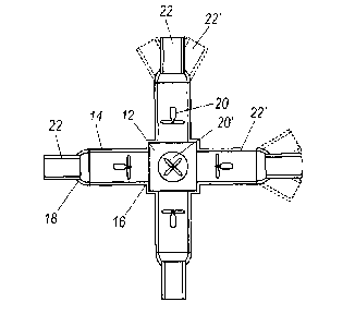
Referring now to Figures land 2, the claimed propulsor 10 structurally
comprises a joint
(central) chamber 12 (see Fig. 1), to which several (four or more, such as six
shown in Figures
1-2) flow passages 14 are connected. With one of its ends, 16, each of the
passages 14 is in
fluid communication with the central chamber 12, with another end, 18, ¨ with
a three-
dimensional gaseous or liquid medium (i.e., with the ambient environment),
which the vehicle is
in. The movement of the working fluid (not shown) in the propulsor passages is
realized by
means of pressure units 20 located in each of the passages. For the
definiteness and illustrative
purposes, the pressure units 20 are depicted as propellers (reversible
propellers are understood),
the propeller 20' being located in the passage which is normal to the plane of
the drawing. The
pressure units 20 provide for a controlled pressure head and flowing of the
working fluid inside
the passages 14 in the direction both to and from the central chamber 12 of
the propulsor.
Nozzles 22 at the outside ends 18 of the passages 14 provide for direction-
controlled exhaust of
the working fluid. Also for illustrative purposes, the nozzles 22 are
conditionally shown as
devices deflecting the working fluid exhaust jet in the drawing plane only,
though all the
reasoning herein is equally valid for the case where the nozzles provide for
the spatial deflection
of the exhaust jet. Reference number 22' shows, as an illustrative, and not
limiting, variant, the
limits of the controlled nozzle jet deflection. In each and every moment, the
pattern of the
working fluid movement through all the nozzles 22, passages 14, and central
chamber 12 of the
5
CA 02838700 2014-02-28
propulsor 10 results from the joint work of all propulsor pressure units 20
inasmuch as there is a
hydrodynamic communication between all the passages 14 via the central chamber
12.
Spatial configuration of the propulsor nozzles 22 can vary depending not only
on
particular structural features of the propulsor such as the number of the
passages 14, but also on
the intended application of the propulsor and demands of the vehicle with
which the propulsor is
to be used. With that in view, believed to be preferable, as far as the
optimization of work is
concerned, but not limiting, is a version where the nozzles are located at the
tops of a visional
centrally symmetric polytope circumscribed about the propulsor, or
configuration versions close
to that.
The claimed propulsor works as follows: in the main operational regime, one or
more
passages 14 suck in gas or liquid from the ambient environment to use it as a
working fluid, the
pressure units 20 of those passages working for suction. Simultaneously, the
pressure units 20
of the remaining passages 14 operate for ejecting the working fluid out to the
ambient
environment, the nozzles 22 of those remaining passages forming the direction
of the ejection
and the speed of ejecting jets from a nozzle depending not only on the
operation of the pressure
unit 20 of the respective passage 14 but also on the operation of the pressure
units 20 of all other
passages 14, both sucking and ejecting, since all the passages 14 are
hydrodynamically
interconnected via the central chamber 12. Upon ejecting working fluid jets,
propulsive efforts
emerge. The magnitude of the propulsive effort is correlated with the speed of
the jet and
depends on the operation of the pressure units 20 of the passages 14.
Propulsive effort moments
(turning forces) are controlled by both nozzle jet deflection and pressure
unit operation.
Summarily, all the emerged propulsive efforts define the direction and
magnitude of the total
propulsor thrust and the direction and strength of the total thrust moment
(turning force).
By controlling the magnitude and direction of pressure head of the pressure
units 20 of
the passages 14, provided that at any moment some of the passages 14 work for
suction and
some ¨ for ejecting the working fluid, and by controlling the direction of
ejecting jets using
6
CA 02838700 2014-02-28
controlled nozzles 22, it is possible to arrive at any propulsor resultant
thrust and resultant thrust
moment in terms of the magnitude/strength and direction thereof (within the
full solid angle), no
matter what the spatial orientation of the propulsor proper is.
Shown in a simplified manner in sketches of Figures 3-6 are examples of
operation of
the propulsor 10 having configuration with six flow passages illustrated by
Figure 1. For
illustrative purposes only, the passages in Figures 3-6 located normally to
the drawing plane are
understood working for suction only in all propulsor regimes reviewed, and
they are not
depicted in these drawings.
Figure 3 schematically shows the propulsor in the configuration illustrated by
Figures 1
and 2. Reference 24 in Figure 3 is the central chamber, reference 26 is one of
the flow
passages, and reference 28 designates one of the nozzles. Reference 30 in
Figure 3 (as well as
in subsequent figures) belongs to arrows going from a passage, to thus show
the direction of jets
of the working fluid when being ejected from the propulsor. Upon the ejection
of the jets,
propelling forces develop providing for propulsor thrust and thrust moment.
Curved and
straight arrows 32 in Figure 3 (as well as in subsequent figures) directed
into the passages
illustrate sucking the working fluid into the propulsor from the outside
environment. Shown for
illustrative purposes only is the embodiment where the propulsor center of
mass coincides with
the center of symmetry of the propulsor. Also for more clearness, the
operation of the propulsor
is described without a vehicle; the propulsor mounted in the vehicle works
likewise.
In the example illustrated by Figure 3, the propulsor ejects working fluid
jets from the
"top" (as conventionally referred to in the drawing and further in the text)
and "left" passages
26 in the "up and left" direction and sucks working fluid from the outside
environment through
the "right" and "bottom" passages 26. The propelling forces emerging in this
jet ejection create
propulsor overall thrust in the "down and right" direction 34 as thrusts add
up, and create no
thrust moment inasmuch as thrust moments of the two passages are cancelled by
each other.
7
CA 02838700 2014-02-28
In the example illustrated by Figure 4, sucking working fluid from the outside
environment is performed through the "top" and "bottom" passages 26. The jets
eject from the
"left" and "right" passages 26 in the directions shown by arrows 36. In this
way a
"counterclockwise" thrust moment of the propulsor and zero overall thrust are
created since
thrusts in such a mode are mutually balanced whereas thrust moments add up.
The operating mode of the propulsor illustrated by Figure 5, where sucking is
shown
being performed through the "bottom" and "right" passages 26 and thrusts
through the "top"
and "left" passages 26, simultaneously provides the thrust in an approximate
direction 38 of
"down-down-right" due to adding up thrusts of the "top" and, in part, "left"
passages 26, and a
"counterclockwise" thrust moment due to the "left" passage 26.
The propulsor operating mode according to Figure 6 simultaneously provides
thrust in
the "down" direction 40 in the drawing, and thrust moment in the
"counterclockwise" direction.
Here, the "down" thrust is created by the jet from the "top" passage 26
whereas thrusts from the
"left" and "right" nozzles 28 cancel each other. The "counterclockwise" thrust
moment is
provided by the nozzles 28 of the "left" and "right" passages 26. Sucking the
working fluid is
performed through the "bottom" passage 26.
The structure of the claimed propulsor gives rise to the following
associations and
limitations. Maximum of thrust and maximum of thrust moment depend on the
structure of a
particular propulsor and are limited by the power of power drives. The peak of
thrust in
propulsor is achieved at zero thrust moment, and the peak of thrust moment ¨
at zero thrust as
these parameters are provided for by same actuators ¨ passage pressure units
and nozzles ¨ and
use same energy source ¨ propulsor power drives.
A structural spatial configuration of the flow passages and nozzles can vary
as
dictated by design features of a particular propulsor and depends, for
example, on the number
of the passages. Based on the propulsor described structural principles, a
number of
8
CA 02838700 2014-02-28
configurations can be proposed that assure thrust and thrust moment spatial
control in the full
solid angle range. Not limiting examples of some of such configurations were
set forth in the
description and shown in the drawings.
As discussed in the above, the propulsor according to the present disclosure
makes it
possible to perform controllable thrust and thrust moment (turn force) in any
direction (in the
full solid angle).
Summing up, the claimed jet propulsor provides controlling simultaneously the
magnitude and spatial direction of thrust in the range of the full solid angle
and the value and
direction of a thrust moment conditional vector in the range of the full solid
angle.
The claimed jet propulsor is intended for the use in means of transportation
or other
apparatuses moving in a three dimensional liquid or gaseous medium such as air
or water, and
provides for thrust and thrust moment.
The propulsor provides controlling the
magnitude/strength and direction of both thrust and thrust moment
simultaneously and
independently, the spatial control of thrust vector and thrust moment
conditional vector being
provided in a spatial range of the full solid angle unaffected by the attitude
of the propulsor
itself. Such a propulsor when moving in a three dimensional liquid or gaseous
medium offers
an enhanced level of maneuverability along with high overall effectiveness.
9