Note: Descriptions are shown in the official language in which they were submitted.
CA 02839140 2014-01-15
CA Application
Blakes Ref.: 75333/00061
ELECTRONIC CONTROL SYSTEM FOR ELECTRIC WATER HEATER
BACKGROUND OF THE INVENTION
[0001] The present invention relates generally to the control of electric
liquid heating apparatus
such as electric water heaters. A relatively recent development in the control
of electric water
heaters is to replace their fairly simple electrical/mechanical heating
control systems with more
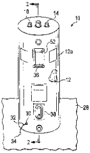
sophisticated and flexible electronic control systems to increase the overall
functionality and
performance of the water heaters. The present invention is directed to the
provision in an electric
water heater of an electronic control system which provides the water heater
with further enhanced
flexibility and performance including, for example, algorithms for protecting
the water heater against
dry firing and providing it with different user-selectable operational modes
to enhance performance
and reduce operational energy costs.
[0002] In a representatively illustrated embodiment thereof, the present
invention provides a dual
element electric water heater having incorporated therein, among other
features, a specially
designed multifunction electronic control system implementing various control
algorithms including a
dry fire protection algorithm, a user-selectable performance mode algorithm,
and a user-selectable
energy saver mode algorithm.
BRIEF DESCRIPTION OF THE DRAWINGS
[0003] FIG. 1 is a perspective view of an electric water heater embodying
principles of the present
invention;
[0004] FIG. 2 is a simplified schematic cross-sectional view through the tank
portion of the electric
water heater taken generally along line 2-2 of FIG. 1;
[0005] FIG. 3 is a schematic electrical wiring diagram for the water heater;
[0006] FIG. 4 is a simplified block diagram of an electronic control/display
portion of the water
heater;
[0007] FIG. 5 is an illustration of the main menu portion of an LCD user
display/operational
selection portion of the water heater;
[0008] FIG. 6 is an illustration of a mode sub-menu portion of the LCD user
display/operational
selection portion of the water heater;
[0009] FIGS. 7A and 7B combined are a logic flow diagram of the overall
control algorithm for the
water heater;
22493196.2 1
CA 02839140 2014-01-15
CA Application
Blakes Ref.: 75333/00061
[0010] FIG. 8 is a logic flow diagram of a dry fire protection algorithm of
the FIG. 7A logic flow
diagram portion; and
[0011] FIG. 9 is a logic flow diagram of a high demand algorithm of the FIG.
7B logic flow diagram
portion.
DETAILED DESCRIPTION
[0012] Illustrated in FIGS. 1 and 2 is a representative embodiment 10 of an
electric water heater
embodying principles of the present invention. While principles of the present
invention are
representatively incorporated in an electric water heater, it will be readily
appreciated by those of
skill in this particular art that such principles may also be advantageously
utilized in a variety of other
types of electric liquid heating apparatus without departing from such
inventive principles.
[0013] Water heater 10 representatively has a vertically oriented cylindrical
metal storage tank 12
(covered with an insulated outer jacket structure 12a) with the usual cold
water inlet and hot water
outlet fittings 14,16 thereon. Respectively and threadingly extending through
outwardly projecting
annular side wall portions 17 of the tank 12 into the interior of the tank 12
are upper and lower
electric heating elements 18,20 having, at their outer ends, enlarged body
portions 18a,20a
disposed on the outer sides of the annular tank portions 17. As indicated in
phantom for the upper
heating element 18 (see FIG. 1), each of the heating elements 18,20 may be
outwardly removed
through its associated annular tank portion 17 as shown by the dashed arrow
"A" in FIG. 2.
[0014] Upper and lower thermistor type temperature sensing elements 22,24 are
in thermal
communication with the tank 12, but do not contact the heating elements 18 and
20, being supported
on retainer members 26 secured to the annular, outwardly projecting tank side
wall portions 17 and
spacing the thermistors 22,24 upwardly apart therefrom. Since the thermistors
22,24 are mounted
on the annular tank portions 17, as opposed to being mounted on and contacting
the heating
element bodies 18a,20a, the heating elements 18,20 may be removed from the
tank without having
to move the thermistors 22,24.
[0015] The thermistors 22,24 indirectly sense the water temperature within
upper and lower
portions of the tank 12, respectively, by externally sensing the temperature
of such upper and lower
tank portions. However, other types of temperature sensors could be
alternatively utilized to directly
sense the tank water temperatures within such upper and lower tank portions.
Accordingly, as used
herein, phrases such as "sensing an upper tank temperature", "detected lower
tank temperature"
and the like are intended to encompass either indirect or direct sensing of
water temperature within
the indicated tank portions. Additionally, phrases such as "a temperature
sensor operative to sense
(or detect) the water temperature in an upper portion of the tank" encompass a
temperature sensor
operative to either directly or indirectly sense such tank water temperature.
22493196.2 2
CA 0 2 8 3 914 0 2014-01-15
CA Application
Blakes Ref.. 75333/00061
[0016] As illustrated in FIG. 1, the lower end of the water heater 10 rests on
a suitable horizontal
support surface, such as a floor 28. Alternatively such support surface could
be the bottom wall of a
drain pan (not shown). Extending outwardly through a small jacket opening 30
adjacent the lower
end of the water heater is a sensing lead structure 32. A suitable water
detector 34 is connected to
the outer end of the sensing lead structure 32 and is positioned on the floor
28 externally of the
water heater 10. Water detector 34, as subsequently described herein, is
integrated with an
electronic controller portion of the water heater 10 and is operative to
detect water leaking from the
tank 12 or originating from other sources, thereby causing the electronic
controller to sound an alarm
and/or shut down the water heater 10.
[0017] Still referring to FIG. 1, on the water heater 10 an upper cavity cover
36 extends outwardly
over the outer end of the upper heating element 18, the upper thermistor 22, a
subsequently
described electronic control board and associated user interface, and an ECO
with associated
harness/wiring. A lower cavity cover 38 extends outwardly over the outer end
of the lower heating
element 20 along with associated harness/wiring, and the lower thermistor 24.
[0018] FIG. 3 show a schematic wiring diagram for the dual heating element
electric water heater
10, the components wired as shown providing the water heater 10 with non-
simultaneous
energization control of its upper and lower electric heating elements 18 and
20. The depicted
electrical circuit comprises the upper and lower heating elements 18 and 20,
the upper and lower
thermistors 22 and 24, the water sensor or detector 34, and a specially
designed electronic control
40 disposed behind the upper cavity cover 36 and as subsequently described
herein. These
components are electrically coupled as schematically shown in FIG. 3 and
receive electrical power
via power leads L1 and L2 via ECO 42 (disposed behind the upper cavity cover
36).
[0019] The electronic control 40 is shown in simplified block form in FIG. 4
and comprises a circuit
board 44 having the indicated connector structures on one side 46 thereof, and
an LCD module 48
on the other side 50 thereof. As subsequently described herein, the LCD module
48 is used to
display various control settings chosen by a user - either at the water heater
10 or remotely through
a data input port 52 on the upper cavity cover 36 of the water heater 10 (see
FIG. 1).
[0020] FIG. 5 shows a main menu display portion 54 of the electronic control
system of the present
invention which is positioned at the upper cavity cover 36 (see FIG. 1). Using
keypad keys 56,58 a
user may respectively adjust the set point temperature of the water heater 10
as shown in the LCD
display area 60. Similar adjustments may be made remotely via the data input
port 52 (see FIG. 1).
Using the key pad associated with the LCD display, the user may also select
the desired operational
mode of the water heater by bringing up the mode sub-menu display 64 shown in
FIG. 6. This gives
the user the choice of an "energy saver" mode 66 or a "performance" mode 68.
The operational
22493196.2 3
CA 02 8 3 914 0 2014-01-15
CA Application
Blakes Ref.: 75333/00061
details of these two user-selectable modes will be subsequently discussed
herein in conjunction with
FIG. 7.
[0021] The logic flow diagram 70 of FIGS. 7A and 7B details the overall
operation of the water
heater 10 provided by the specially designed electronic control system of the
present invention via
the electronic control 40 (schematically depicted in FIGS. 3 and 4). Turning
now to FIG. 7, in
response to the initial power up of the water heater 10 at step 72 the system,
at step 74, reads the
tank temperatures detected by the upper and lower thermistors 22 and 24 and
determines, at step
76 (with neither of the heating elements 18,20 yet energized), whether there
is a heat demand in the
top portion of the tank 12. If there is, a transfer is made to step 78 at
which a subsequently
described dry fire routine or algorithm is carried out to test for a dry fire
condition. If the dry fire test
is passed, a transfer is made to a main control algorithm 80. If the dry fire
test is failed, as
subsequently described an error is set and the heating elements are shut down.
[0022] The main algorithm 80, when initiated, first determines, at step 82,
which operational mode
has been selected by the user. If the performance mode has been selected, the
performance mode
is initiated at step 84 by a transfer to step 86 at which a query is made as
to whether a heat demand
is present in the top portion of the tank (as detected by the upper thermistor
22). If there is a top
heat demand, a transfer is made to step 88 at which the lower heating element
20 (if on) is turned off
and, after a predetermined delay (representatively 30 seconds) the upper
heating element 18 is
turned on. If the lower heating element 20 is already off, the upper heating
element 18 is turned on
without such a time delay.
[0023] Next, at step 90 a query is made as to whether the upper tank
temperature (as sensed by
the upper thermistor 22) is less than 100 degrees F. If the answer to the
query is "yes" a transfer is
made to a subsequently described high demand routine 92. If the requirements
of the high demand
routine 92 are met, a transfer is made to step 94 at which a main high demand
algorithm is initiated.
If the answer to the query at step 90 is "no", a transfer from step 90 to step
94 is made, bypassing
the high demand routine at step 92.
[0024] The initiation of the main high demand algorithm at step 94 causes a
transfer to step 96. If
the answer to the step 86 query is "no", a transfer is also made to step 96,
via step 87 at which the
upper heating element 18 is turned off. At step 96 a query is made as to
whether there is a heat
demand present in the bottom tank portion (as detected by the lower thermistor
24). If there is, a
query is made at step 98 as to whether the upper heating element 18 is on. If
it is, a transfer is
made from step 98 back to the main algorithm step 80. If it is not, a transfer
is made from step 98 to
step 100 at which the lower heating element 20 is turned on and a transfer
made from step 100 back
to the main algorithm step 80. If the answer to the step 96 query is "no", a
transfer is made from
22493196.2 4
CA 02 8 3 914 0 2 014- 01-15
CA Application
Blakes Ref.: 75333/00061
step 96 to step 102 at which both heating elements 18,20 are turned off and a
transfer is made from
step 102 back to the main algorithm step 80.
[0025] If at step 82 it is determined that the user has selected the energy
saver mode of operation
, of the water heater 10, the energy saver mode is initiated at step 104 by a
transfer to step 106 at
which a query is made as to whether the user-selected setpoint temperature is
greater than 130
degrees F. If it is, a transfer is made to step 108 at which the setpoint is
reduced to 130 degrees F
(or some other predetermined magnitude). A transfer is then made to step 110
from step 108. If the
answer to the step 106 query is "no", a transfer is also made (from step 106)
to step 110.
[0026] At step 110 the control system adjusts the water heater setpoint
temperature and differential
(the difference between the water heater setpoint temperature and the lower
water temperature at
which a call for heat is initiated) based on the sensed time between the
current heat demand and the
immediately prior heat demand. For example, if the time between these two
successive heat
demands is sufficiently long, the setpoint temperature may be lowered by a
predetermined amount
and/or the temperature differential increased by a predetermined amount.
[0027] From step 110 a transfer is made to step 112 at which a query is made
as to whether there
is a heat demand present in the top tank portion. If there is, a transfer is
made to step 114 at which
the upper heating element 18 is turned on - either immediately if the lower
heating element 20 is off,
or after a minimum predetermined time delay (illustratively 30 seconds) after
turning the lower
element off. A transfer is then made from step 114 to step 116. Alternatively,
if the answer to the
step 112 query is "no", a transfer is made from step 112 to step 116. At step
116 a query is made as
to whether there is a heat demand present in the bottom tank portion. If there
is not, a transfer is
made from step 116 to step 118 at which both of the upper and lower heating
elements 18,20 are set
to off and a transfer is made from step 118 back to the main algorithm step
80.
[0028] If the answer to the step 116 query is "yes", a transfer is made from
step 116 to step 120 at
which a query is made as to whether the upper heating element 18 is on. If it
is, a transfer is made
from step 120 back to the main algorithm step 80. If it is not, a transfer is
made from step 120 to
step 122 at which the lower heating element 20 is turned on and a transfer is
made from step 122
back to the main algorithm step 80.
[0029] The various steps in the previously mentioned dry fire routine 78 shown
in FIG. 7A are
detailed in the logic flow chart of FIG. 8. Initiation of the dry fire routine
78 causes the sequential
performance of steps 124-134.
[0030] At step 124 a dry fire test is initiated by starting a dry fire
incremental timer, storing a
parameter "sample #1" having a value equal to the upper thermistor -sensed
temperature, and
keeping the upper heating element 18 off.
22493196.2 5
CA 0 2 8 3 914 0 2014-01-15
CA Application
Blakes Ref.: 75333/00061
[0031] At step 126 the system waits a predetermined time (representatively 30
seconds) after the
start of the timer.
[0032] At step 128 the system stores a parameter "sample #2" having a value
equal to the upper
thermistor-sensed temperature.
[0033] At step 130 the upper heating element 18 is turned on.
[0034] At step 132 the system waits a predetermined time (representatively 30
seconds) until the
dry fire timer elapsed time is greater than 60 seconds.
[0035] At step 134 the upper heating element 18 is turned off and a transfer
is made to step 136 at
which a query is made as to whether the magnitude of the parameter "sample #2"
is greater than the
magnitude of the parameter "sample #1". If it is not, at step 138 the value of
a parameter
"dry_fire_offset" is set to zero and a transfer is made to step 140. If the
answer to the step 136
query is "yes", at step 142 dry_fire_offset is set to the value 2(sample_2 -
sample_1) unless such
value is greater than 1 in which case dry_fire_offset is set to the value of
1. A transfer is then made
from step 142 to step 140.
[0036] At step 140 a query is made as to whether the temperature detected by
the upper thermistor
22 is greater than the magnitude (sample_2 + 2.5 degrees F + dry_fire_offset).
If it is, the dry fire
test is failed and a transfer is made from step 140 to step 144 which triggers
the setting, at step 146,
of an error and a shut down of the heating elements 18 and 20. If the answer
to the step 140 query
is "no", a transfer is made from step 140 to step 148 at which a query is made
as to whether the time
on the dry fire timer has reached a predetermined value (representatively 105
seconds). If it has
not, the system loops back through steps 140 and 148 until the timer reaches
105 seconds at which
time the dry fire test is passed and a transfer is made from step 148 to step
150, thereby triggering,
at step 152, a return to the main algorithm 80 in the previously described
FIG. 7A flow chart portion.
[0037] The calculation and use of the "dry_fire_offset" parameter incorporated
in the dry fire
protection algorithm 78 is a primary feature of the algorithm and serves to
eliminate spurious dry fire
condition indications when, just before the upper heating element 18 is
energized in step 130 of the
dry fire algorithm 78 the tank water temperature is rising due to, for
example, water flowing into the
tank 12 having a temperature higher than the tank water in an upper portion of
the tank, or the tank
water temperature rising due to the effects of a higher external ambient
temperature. As can be
seen in step 140 of the algorithm 78, the inclusion of the "dry_fire_offset"
parameter in the dry fire
temperature calculation provides a measure of compensation for this water
temperature rise
occurring prior to the test firing of the upper heating element 18.
Preferably, as described above, the
dry fire protection algorithm is called into play only in the event that the
water heater 10 is being
22493196.2 6
CA 02839140 2014-01-15
CA Application
Slakes Ref.: 75333/00061
initially powered up. Alternatively, however, the dry fire protection
algorithm 78 can be utilized at the
start of every heating demand cycle if desired.
[0038] The steps in the high demand routine 92 shown in the FIG. 7B flow chart
portion are
depicted in the logic flow chart of FIG. 9. When the high demand subroutine is
reached at step 92, a
transfer is made to step 154 at which a query is made as to whether a heat
demand exists in the top
tank portions. If it does not, a transfer is made back to the main high demand
algorithm 94 shown in
the FIG. 7B logic flow chart portion. If such upper tank heating demand does
exist, a transfer is
made from step 154 to step 156 at which a query is made as to whether the
lower tank temperature
(sensed by the lower thermistor 24) is less than 80 degrees F. If it is, a
transfer is made from step
156 to step 158. If it is not, a transfer is made from step 156 to step 160 at
which a query is made
as to whether the rate of lower tank temperature change is greater than a
predetermined change
rate (representatively 0.055 degrees F/second). If it is not, a transfer is
made from step 160 back to
the main high demand algorithm 94 shown in FIG. 7. If it is, a transfer is
made from step 160 to step
158.
[0039] At step 158 a query is made as to whether the sensed upper tank
temperature is less than a
predetermined magnitude (representatively 100 degrees F). If it is not, a
transfer is made from step
158 to step 162 at which a query is made as to whether the rate of change of
the sensed upper tank
temperature is greater than a predetermined magnitude (representatively 0.09
degrees F). If it is
not, a transfer is made from step 162 back to the main high demand algorithm
94 shown in FIG. 7. If
it is, a transfer is made from step 162 to step 164. Similarly, if the step
158 query answer is "yes" a
transfer is made from step 158 to step 164. At step 64 the appropriate heating
element
(representatively the upper heating element 18) to meet the high demand
condition and a transfer is
made to the previous step 154.
[0040] Briefly summarizing the user-selectable "performance" and "energy
saver" modes, with the
exception of the specially designed high demand algorithm 92 therein, the
performance mode is
generally similar to a conventional non-simultaneous actuation control method
for dual heating
elements in an electric water heater in which operational priority is given to
the upper heating
element over the lower heating element. In such method, the upper and lower
heating elements
cooperate during a heat demand to raise the upper tank temperature in
satisfying the heat demand.
[0041] When the high demand algorithm 92 is called into play in the selected
performance mode of
the present invention, however, only the upper heating element 18 is utilized
to fully heat up the
water in the upper tank portion, and the final temperature in such upper tank
portion is higher than
when the high demand algorithm 92 is called into play.
22493196.2 7
CA 02839140 2015-09-22
[0042] The following is an example of the contrast between the performance
mode operation with
and without the high demand algorithm 92 being utilized therein. For purposes
of comparison
between the utilization and non-utilization of the high demand algorithm 92 in
the performance
mode, it will be assumed that the water heater set point temperature is 135
degrees F, the top
heating element temperature differential is 9 degrees F, the bottom heating
element temperature
differential is 13 degrees F, and the tank temperature is 115 degrees F for
the entire tank.
[0043] Where the high demand algorithm 92 is not utilized in the performance
mode, the upper
heating element will come on and satisfy the tank until 131 degrees F
(representatively 4 degrees F
lower than the set point temperature) to reduce the overshoot induced by the
lower element. Then
the lower heating element will come on and induce an overshoot at the top
portion of the tank that
will take the upper tank temperature to 135 degrees F before reaching 135
degrees F in the bottom
tank portion as well.
[0044] In contrast, when the high demand algorithm 92 is utilized in the
performance mode, the
upper heating element will come on until the upper temperature reaches 135
degrees F. The bottom
heating element will come on after that.
[0045] When selected by a user, the energy saver mode provides a desirable
energy cost saving
by adjusting the water heater's set point and/or temperature differential as a
function of detected
times between successive water heating demands.
[0046] The foregoing detailed description is to be clearly understood as being
given by way of
illustration and example only, the scope of the present invention being
limited solely by the
appended claims.
8
22794007.1