Note: Descriptions are shown in the official language in which they were submitted.
CA 02839224 2016-11-25
1
MECHANISM FOR TOOL, METHOD AND MARKING SYSTEM
FIELD OF THE INVENTION
MECHANISM FOR TOOL, METHOD AND MARKING SYSTEM, pertains generally to
marking, tracing and/or measuring surfaces adjacent to the curved and/or off
angle object's surface,
positioned perpendicularly to the working surface or positioned on the same
surface plane as the
= object's surface. Particularly, the present invention should and/or will
be useful for the assistance
with tracing/marking/measuring: hardwood/laminate/parquet/engineering
flooring, and/or tile/floor
tile, and/or any kind of residential and/or commercial construction workers
and/or for amateur users.
BACKROUND OF THE INVENTION
The present invention is an accurate tracing/marking/drawing mechanism that
can be used
with any frame and/or in particular with application of patented invention:
TOOL, METHOD AND
MARKING SYSTEM of Canadian Patent No. 2,625,566, US Patent No. 8,127,457 B2,
where such
invention is an upgraded system to said patents. In the field where one
surface should align perfectly
to the other surface either perpendicularly or positioned on the same surface
plane as the object's
surface, where the adjoining surface to the object's surface is shaped or
off/angle, the actual work
(drawing exact contour on a working surface and cutting it) is very complex.
Many construction
workers are struggling with performing the actual work correctly without the
proper marking
system, and/or they are omitting projects which involve complicated cuts on
different surfaces
(sometimes such job involves many different surfaces and/or cuts). Only
craftsmen and/or skilled
and/or determined people are able to perform the challenging, curved/off angle
cutting job.
Therefore, the job should be done ideally that anyone who looks at the
performance should admire
the craftsmanship of a particular worker. Workers are dealing with difficult
cuts by using carpentry
tools and/or by their own ways of simplifying the process of their work. In
addition, it takes a great
amount of time to complete curved/off angle cuts on a long/short and /or
curved/off angle surface.
Currently there is patented device: TOOL, METHOD AND MARKING SYSTEM of Patent
No.
2,625,566, US Patent No. 8,127,457 B2, which is helping contractors and/or
amateur workers by
CA 02839224 2016-11-25
9
limiting time spent on difficult cuts and ideal aligning to the assigned
surface. Although the patented
device is working perfectly, the improved/new mechanism is more accurate and
without creating
shape limits, that also could be used with said patents for the better
performance. Prior to the:
TOOL, METHOD AND MARKING SYSTEM, a professional worker has his/her working
system,
it took him/her several hours to draw and to cut the actual size of an
adjacent surface to the
perpendicular object's surface and/or to the object's surface positioned on
the same plane level as
the working surface, that aligned ideally. The time contractors invested into
the performance usually
extended their originally scheduled time. Naturally, there is need to simplify
the project and at the
same time minimize the actual time consuming the assignment but also maximize
the quality of the
so called professional job and/or allow other contractor workers to be
assigned and equipped to
perform the assignment. It is an object of the present invention to provide a
new mechanism that
will work perfectly with the already patented device which is TOOL, METHOD AND
MARKING
SYSTEM, the MECHANISM FOR TOOL, METHOD AND MARKING SYSTEM will ideally
satisfy the need of craftsmanship's and/or contractor worker's and/or amateur
user's needs. Matter
and advantages of the present invention will be apparent from the description
of the invention
provided herein.
SUMMARY OF THE INVENTION
The present invention provides a mechanism/tool and system of ideally placed
particles
within the frame tool, that when in motion, the ideal shape can be obtained.
The mechanism includes
movable in four direction parts, along with the marking instrument and
stopper. The components are
carefully assembled to obtain the highest quality contour reader/tracer
mechanism.
Operating the MECHANISM FOR TOOL, METHOD AND MARKING SYSTEM will
allow:
- an accurate marking/drawing line on a required/working surface aligning
ideally to the
perpendicular object's surface and/or to the object's surface positioned on
the same plane
level as the working surface, that may be curved, off angle, or straight;
- an accurate shape that will allow after cutting, align ideally to the
perpendicular object's
surface and/or to the object's surface positioned on the same plane level as
the working
surface, that may be curved, off angle, or straight;
CA 02839224 2016-11-25
3
- an accurate shape and size of required surface that will align ideally to
the perpendicular
object's surface and/or to the object's surface positioned on the same plane
level as the
working surface, that may be curved, off angle, or straight;
- an accurate marking/drawing line, will be performed on a surface that has
a variety of
textures (ex. hardwood flooring, laminate flooring, parquet flooring,
engineering flooring,
tile, or other);
- shorten the time spent on the job site by the craftsmen and/or by the
professional contractor
workers along with the amateur performers. Time is an expensive factor in the
present world;
therefore by using the MECHANISM FOR TOOL, METHOD AND MARKING SYSTEM,
the working time is automatically shortened;
- accept the contract while the job involves difficult cuts;
- allows the worker to perform the job accordingly.
The present invention will have the advantage of an easy to operate tool
scheme, such as:
- easily movable, easy to handle;
- stable during performance of the actual assignment;
- allowing for an accurate reading of the sought shape and/or size of the
surface that should
align ideally to the adjacent surface;
- allowing any person willing to learn to operate the present invention;
- the device is working in four directions: rightward, leftward, upward,
downward;
- full control over the composition, allowing the operator to move manually
rightward and/or
at the same time upward or downward; furthermore, the operator may move the
marking
instrument leftward and/or at the same time upward or downward, according to
his/her
assigned project.
CA 02839224 2016-11-25
4
DETAILED DESCRIPTION OF DRAWINGS
Features and advantages of the present invention can be understood in detail;
a more
particular description of the invention, briefly summarized beneath, may and
will reference to the
embodiments thereof that are illustrated in the appended drawings. It is to be
noted, however, that
the appended drawings illustrate the typical embodiments of this invention and
are, therefore, not to
be considered limiting of its scope, for the invention may admit to other
equally effective
embodiments.
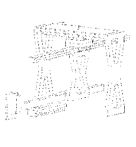
Figure 1 Represents the MECHANISM FOR TOOL, METHOD AND MARKING
SYHSTEM as a complete composition ready to operate, mounted to the frame
system.
Figure 2 Represents the convertible marking assembly of the: MECHANISM
FOR
TOOL, METHOD AND MARKING SYHSTEM; the following are the references to the
drawing:
a) slider,
b) connector,
c) connecting tube,
d) holding tube,
e) marking hole,
f) marking instrument,
g) marker.
Figure 3 Represents the movable assembly of the: MECHANISM FOR TOOL,
METHOD AND MARKING SYSTEM: the following are the references to the drawing:
a) slider,
a-l)perpendicular slider,
h) perpendicular slider holder,
h-1)perpendicular slider holder opening,
i-1) rolling wheels upper,
i-2) rolling wheels bottom,
j) square blocks,
k) stopper /safety break,
n) frame system,
CA 02839224 2016-11-25
1) wood holder/holder.
Figure 4
Represents the movable/adjustable marking instrument of the: MECHANISM
FOR TOOL, METHOD AND MARKING SYSTEM: the following are the references to the
drawing of marking instrument of Figure 2 f):
f-I) head (view from both sides ¨ top and bottom),
f-2) sliding neck,
f-3) neck,
f-4) pin holes,
f-5) pin.
CA 02839224 2016-11-25
6
DETAILED DESCRIPTION OF THE INVENTION
Before explaining the present invention in details, it is to be understood
that the invention is
not limited to its application to the details of construction and arrangement
of parts illustrated in the
accompanying drawings. Moreover, it is to be understood that the phraseology
and terminology
employed herein is for the purpose of description and not of limitation.
In accordance with the present invention, and referring to Figure 1, the
composition
comprises the complete invention, ready to be used/mounted/installed to the
frame system.
Referring to Figure 1, wherein the said mechanism system is the complete
mechanism that is
made with, but not limited to, metal, plastic or any durable material that
will suit the needs of
demands of the mechanism for a marking tool, especially as an innovative
upgrade to the patented
TOOL, METHOD AND MARKING SYSTEM of Patent No.2,625,566, US Patent No.
8,127,457
B2.
Referring to Figure 2, wherein the slider, Figure 2a), slides into the rolling
wheels, Figure 3
i-2), connecting the parts for the perpendicular movement of a slider, Figure
2a), to the
perpendicular slider, Figure 3 a-1). The connector, Figure 2b), is of any
convenient shape and
connects the slider, Figure 2a), with the connecting tube, Figure 2c), the
connector unit is affixed
into the slider from one side and into the connecting tube from the other side
placing them parallel
to each other. The holding tube, Figure 2d), is inserted inside the connecting
tube, Figure 2c), and
contains marking holes, Figure 2e), for the marker, Figure 2g), to be inserted
inside the marking
hole. The marking instrument, Figure 2f), is inserted into the holding tube,
Figure 2d).
Referring to Figure 3, wherein the perpendicular slider holder, Figure 3h),
and perpendicular
slider, Figure 3 a-1), are connected together and mounted by the ends to the
frame system, Figure
3n), of any marking tool, or in particular to the patented TOOL, METHOD AND
MARKING
SYTEM. Following, the square block, Figure 3j), holds rolling wheels, Figure
3i-1 and 3i-2), in
equal number/distance from both sides of the block (two sets of rolling
wheels), where the upper set
CA 02839224 2016-11-25
7
of the rolling wheels, Figure 3i-1), is inserted onto the perpendicular
slider, Figure 3 a-1), and slides
easily from one side to the other side. The stopper, Figure 3k), stops and
controls the motion of any
movement of the square block and both sliders, Figure 3 a-1) and Figure 2a).
The slider holder
opening, Figure 3 h-1), allows the mechanism to stop in specific position
required by the operator.
The wood holder (holder), Figure 31), holds the material to be traced on
parallel to the slider, Figure
2a), allowing the marker, Figure 2g), touch the surface.
Referring to Figure 4, wherein the marking instrument encompasses a head,
Figure 4 f-1),
that slides into the sliding neck, Figure 4 1-2), where the neck, Figure 4 f-
3) is mounted to the back
of sliding neck of Figure 4 f-2), to be inserted and fastened into the holding
tube, Figure 2d). The
head includes four pin holes, Figure 4 f-4), for the pin, Figure 4m), to go
through and touch the
surface in position where needed to obtain the necessary reading.
To operate with this invention, the perpendicular slider holder, Figure 3h),
with perpendicular slider,
Figure 3 a-1), must be mounted into the frame system, Figure 3n), of a
tool/machine, where such
frame system, Figure 3h) includes a wood holder on one side, Figure 31), where
such wood holder
holds the object (hardwood, laminate, engineering, flooring of any surface) in
still perfect fit parallel
position to the slider Figure 2a). The contractor worker and/or amateur
performer/tool operator can
easily operate the MECHANISM FOR TOOL, METHOD AND MARKING SYSTEM by placing
the tool (said mounted composition) on the tracing surface, securing the
object of the contour tracing
inside the wood holder, Figure 31), with direction of the invention facing the
surface from which the
contour will be transferred; furthermore, the tracing surface can be located
on the same surface
plane as the contoured/irregular shaped/off angle/curved surface, or the
tracing surface can be
located perpendicular to the contoured/irregular shaped/off angle/curved
surface that is difficult to
mark/trace the contour without the tool. To place the composition on a
designated surface, position
the slider along the surface plane with the stopper on/fastened, Figure 3k),
not allowing to move the
slides, Figure 2a) and Figure 3 a-1), locate marking instrument, Figure 2f),
by the
contoured/irregular shaped/off angle/curved surface, allowing the pin, Figure
4m), to touch the
necessary contour, at the same time have ready marker, Figure 2g), in the
necessary marking hole,
Figure 2e); furthermore, loosen the stopper, Figure 3k), and using hands allow
the pin touch the
contoured surface and the marker the tracing surface, marking the surface
accordingly to the
contour. The motions of the sliders are in four directions: rightward-
leftward, downward-upward,
the rolling wheels help to slide the slider in an ideal motion leaving the
perfect contour
CA 02839224 2016-11-25
8
traced/marked to be cut and inputted/installed in the place. The marker is
placed in the marking hole
and in tube with gravity system (patent pending application), to obtain the
best results of the
contour/marker. Once the tracing/marking is performed, the stopper must be
fastened and the
procedure repeated until the work is completed.