Note: Descriptions are shown in the official language in which they were submitted.
CA 02839293 2016-04-13
1
BEVERAGE FORMATION APPARATUS AND METHOD USING VIBRATORY ENERGY
This application is a continuation in part of U.S. Application 12/971,535,
filed Dec. 17,
2010, which claims the benefit of U.S. Provisional applications 61/284,477,
filed Dec. 18, 2009
and 61/335,083, filed Dec. 31, 2009, which are all hereby incorporated by
reference in their
entireties. This application claims the benefit of U.S. Application
61/497,287, filed June 15,
2011 and U.S. Application 61/500,241, filed June 23, 2011, which are hereby
incorporated by
reference in their entirety.
BACKGROUND
Various patents describe the use of sonic energy when brewing coffee,
including U.S.
Patent 4,779,520, U.S. Patent 4,983,412, and U.S. Patent Publication
20080032030 which
describe applying ultrasonic energy to the exterior of a drip-brewing funnel
and/or directly to
the coffee grounds and water at the interior of the funnel. However, applying
ultrasonic
energy to the exterior of a brew funnel will not necessarily allow for
suitable control of the
sonic energy at the interior of the brew funnel, e.g., resulting in some areas
receiving energy
of a different intensity and/or frequency than other areas. Also, applying
sonic energy to the
interior of a brew funnel may in some cases to cause erosion of an ultrasonic
probe having a
metal exterior, resulting in the possibility that eroded material is deposited
in the coffee
grounds or other beverage medium.
SUMMARY OF INVENTION
In one aspect of the invention, there is provided a beverage cartridge
arranged for use
in a beverage forming machine to make a beverage, comprising:
a container having an opening, a lid closing the opening, and a closed
interior space;
a beverage medium located in the closed interior space, the beverage medium
being
used to form a beverage by interaction of the beverage medium with a liquid
introduced into
the closed interior space; and
a motion creating structure in the closed interior space, the motion creating
structure
being, with the lid closed, arranged to cause movement of the beverage medium
or liquid in
the cartridge relative to the container in response to oscillatory movement of
a drive system
CA 02839293 2016-04-13
la
located outside of the closed interior space and separable from the beverage
cartridge, the
motion creating structure including an agitator that is in the closed interior
space and is either
attached to the container or is provided as one or more mixing balls that are
movable in the
closed interior space independently of the container.
In another aspect, there is provided a method for forming a beverage using a
beverage
cartridge arranged for use in a beverage forming machine, comprising:
providing a beverage cartridge including:
a container having an opening, a lid closing the opening, and a closed
interior
space,
a beverage medium located in the interior space, and
a motion creating structure in the closed interior space of the container, the
motion creating structure being, with the lid closed, arranged to cause
movement of the beverage medium;
associating the beverage cartridge with a brew chamber of the beverage forming
machine; and
causing movement of the motion creating structure while the cartridge is
associated
with the brew chamber to cause movement of the beverage medium in the closed
interior
space.
In another aspect, there is provided a beverage forming system, comprising:
a cartridge receiver arranged to hold a beverage cartridge;
a liquid inlet arranged to introduce liquid into the beverage cartridge;
a drive system arranged to provide vibratory energy to the beverage cartridge;
and
a beverage cartridge, including:
a container having an opening, a lid closing the opening, and a closed
interior
space;
a beverage medium located in the interior space, the beverage medium being
used to form a beverage by interaction of the beverage medium with a liquid
introduced into the interior space; and
CA 02839293 2016-04-13
lb
a motion creating structure in the closed interior space of the container, the
motion creating structure being, with the lid closed, arranged to cause
movement of
the beverage medium or liquid in the cartridge relative to the container in
response to
oscillatory movement of the drive system located outside of the closed
interior space
and separate from the beverage cartridge.
Aspects of the invention relate to applying vibratory or other sonic energy to
the
interior of a beverage cartridge that contains a beverage medium and a liquid
introduced into
the cartridge interior. The cartridge may be arranged to have a sonic receiver
that receives
sonic energy for introduction into the interior space of the cartridge. For
example, the sonic
receiver may include an acoustically compliant portion of the cartridge that
vibrates or
otherwise moves in response to the sonic energy so as to itself transmit sonic
energy to the
cartridge interior. In another arrangement, the sonic receiver may include a
motion creating
structure that is arranged to cause beverage medium and/or liquid in the
cartridge to move in
response to vibratory motion of the motion creating structure caused by a
sonic emitter or
other oscillating drive system. In some other embodiments, the sonic receiver
may include an
acoustically transparent portion, an acoustic coupling medium, a depression or
other feature
to interact with a sonic emitter, or other feature to allow the sonic emitter
to transmit sonic
energy directly into the cartridge. The sonic receiver may be arranged to
direct sonic energy
CA 02839293 2013-12-12
WO 2012/174331
PCT/US2012/042586
to particular areas of the interior space of the cartridge, focus, disperse or
otherwise modify
the sonic energy to make the intensity of the sonic energy more uniform in at
least parts of
the interior space, and/or have other affects on the sonic energy. This may
help avoid
problems associated with having sonic energy concentrated in one or more
areas, such as
tunneling where the sonic energy effectively forms a pathway in a beverage
medium through
which liquid may "short circuit" or pass through the cartridge without
sufficiently contacting
the beverage medium. Tunneling can cause a resulting beverage to be weak
because of the
insufficient contact of liquid with the beverage medium.
In one aspect of the invention, a beverage cartridge arranged for use in a
beverage
forming machine to make a beverage may include a container having a closed
interior space
and a beverage medium located in the interior space. The beverage medium may
be used to
form a beverage by interaction of the beverage medium with a liquid introduced
into the
interior space and may include, for example, roast and ground coffee,
sweeteners, creamers,
instant drink mixes, and other soluble and/or insoluble materials. A motion
creating structure
may also be included in the closed interior space of the container and
arranged to cause
movement of the beverage medium or liquid in the cartridge relative to the
container in
response to oscillatory movement of a drive system located outside of the
closed interior
space and separate from the beverage cartridge. For example, the motion
creating structure
may include an agitator that includes a first portion located in the interior
space and a second
portion that extends outside of the interior space. The second portion of the
agitator may be
arranged to mechanically couple with the drive system so that motion of the
drive system
may be translated to the first portion of the agitator in the cartridge. The
agitator may have a
variety of different arrangements, e.g., to cause vibratory motion, stirring,
cavitation, or other
mixing motion of the beverage medium and/or liquid. In some embodiments, an
agitator may
be attached to the container and extend into the interior space, e.g., one or
more paddles,
fingers, fins, tabs or blades may be attached to a container sidewall and
extend into the
interior space for interaction with the beverage medium, liquid, a filter or
other component in
the interior space.
In another illustrative embodiment, the motion creating structure may include
indentations in the container that are arranged to mechanically couple with
the drive system.
The indentations may provide mechanical coupling of the container to the drive
system, e.g.,
to allow the drive system to move the cartridge as a whole, or may function to
cause
movement of the beverage medium or liquid in the container, e.g., the
indentations may act as
2
CA 02839293 2013-12-12
WO 2012/174331
PCT/US2012/042586
fins, blades or other structures that cause motion of the beverage medium
and/or liquid in
response to movement of the container.
In another illustrative embodiment, the motion creating structure may include
one or
more mixing balls that are movable in the interior space independently of the
container. The
mixing balls may be arranged to create movement of the beverage medium or
liquid in the
container in response to movement of a container by the drive system, e.g.,
the container may
be rotated in an oscillating manner that causes the balls to rotate relative
to the container in
the interior space. Alternately, the mixing balls may be caused to move in a
random way,
vertically or other linear fashion, or otherwise to cause movement of the
beverage medium or
liquid.
In another embodiment, the motion creating structure may include one or more
wall
elements in the interior space arranged to cause net rotary movement of the
beverage medium
or liquid in response to oscillatory rotation of the container. For example,
the wall elements
may have a zig-zag, a "ramp and stop" or other arrangement capable of causing
rotation of
the beverage medium and/or liquid in response to oscillatory rotation of the
container.
The cartridge may include any suitable features found in beverage cartridges,
such as
one or more filters, liquid distributors, one or more different types of
beverage media in one
or more different compartments of the cartridge, liquid or gas inlet or outlet
valves or other
conduits or ports, etc. For example, the cartridge container may include a cup
with a top
opening and a lid attached to the cup that closes the top opening. The cup may
have a
cylindrical shape, a cubic shape, conical or frustoconical shape, partial
spherical shape,
tetrahedral shape, or others. The cup may be made as a single part, e.g., a
single
thermoformed piece of plastic, or may be made of multiple parts that are
joined together. For
example, a cup may include a cylindrical wall member that has a flat plate or
foil member
attached to one end of the cylindrical wall. Similarly, the lid may be
arranged in any suitable
way, e.g., may include a single part such as a layer of laminated foil,
multiple parts joined
together, and so on. In addition, the cartridge may include a filter element
arranged to filter
at least part of a beverage formed by interaction of the beverage medium with
liquid. For
example, the filter element may include a filter paper arranged so that liquid
interacting with
the beverage medium passes through the filter before exiting the cartridge.
The filter may be
attached to a lid of the container, a container sidewall, or other cartridge
component(s).
In another aspect of the invention, a beverage forming system includes a
cartridge
receiver arranged to hold a beverage cartridge, a liquid inlet (such as a
needle that pierces the
cartridge) arranged to introduce liquid into the beverage cartridge, and a
drive system
3
CA 02839293 2013-12-12
WO 2012/174331
PCT/US2012/042586
arranged to provide vibratory or other sonic energy to the beverage cartridge.
A beverage
cartridge may be held by the cartridge receiver and have an arrangement like
that described
above, e.g., including a container having a closed interior space, a beverage
medium located
in the interior space, and a motion creating structure in the closed interior
space of the
container. The motion creating structure may be arranged, e.g., as discussed
above, to cause
movement of the beverage medium or liquid in the cartridge relative to the
container in
response to oscillatory movement of the drive system. The system may be
arranged to pierce
the cartridge container to form an opening through which beverage exits the
container, e.g., a
needle may pierce the container to allow beverage to exit the container.
In some embodiments, the drive system and motion creating structure may be
arranged to cause materials to pass through a filter in the cartridge that
would not pass
through the filter in the absence of causing movement of the beverage medium
or liquid. For
example, when using the system to create a coffee beverage, the drive system
and motion
creating structure may cause the coffee beverage to be formed with a turbidity
and/or a level
of total dissolved solids that is higher than would be present in the absence
of movement of
the beverage medium or liquid by the motion creating structure and the drive
system.
In another aspect of the invention, a method for forming a beverage using a
beverage
cartridge includes providing a beverage cartridge including a container having
a closed
interior space, a beverage medium located in the interior space, and a motion
creating
structure in the closed interior space of the container arranged to cause
movement of the
beverage medium. The beverage cartridge is associated with a brew chamber of a
beverage
forming machine, e.g., by placing the cartridge in a cartridge receiver of the
beverage
forming machine. Movement of the motion creating structure is caused while the
cartridge is
associated with the brew chamber to cause movement of the beverage medium in
the closed
interior space. Such motion may cause the beverage medium to better interact
with liquid
(e.g., water) that is introduced into the cartridge when forming a beverage.
Improved
interaction may result in more complete or faster extraction, more complete or
faster mixing,
improved passage of liquid and/or other materials through a filter, and/or
other features.
In one embodiment, the step of causing movement may include engaging and
causing
oscillatory motion of an agitator that has at least a portion located in the
interior space of the
cartridge. For example, the agitator may include a first portion located in
the interior space
and oscillatory motion of the second portion (which extends outside of the
cartridge for
engagement with a drive system) causes movement of the first portion. As
discussed above,
the motion creating structure may be arranged in a variety of different ways,
and movement
4
CA 02839293 2013-12-12
WO 2012/174331
PCT/US2012/042586
of the motion creating structure may be caused by mechanical engagement with
and
movement of the motion creating structure, movement of the cartridge
container, and/or
movement of a drive system component introduced into the cartridge interior.
A sonic emitter or other drive system that provides sonic or vibratory energy
may take
any one of a variety of forms, such as a probe that is positioned adjacent a
portion of the
cartridge, a motor and drive linkage, etc. As used herein, "sonic energy" or
"vibratory
energy" includes energy audible to the human ear as well as energy outside of
the range of
hearing of the human ear. For example, "sonic energy" or "acoustic energy" or
"vibratory
energy" can include vibratory energy having a frequency of about 10Hz to about
200kHz or
more.
These and other aspects of the invention will be apparent from the following
description and claims.
BRIEF DESCRIPTION OF THE DRAWINGS
Aspects of the invention are described with reference to the following
drawings in
which like numerals reference like elements, and wherein:
FIG. 1 is a side cross-sectional view of a cartridge in accordance with
aspects of the
invention;
FIG. 2 is an exploded perspective view of the cartridge of FIG. 1;
FIG. 3 is a side cross-sectional view of the cartridge of FIG. 1 after a
surface of the
cartridge is pierced by a piercing element;
FIG. 4 shows a cross sectional view of another illustrative embodiment of a
cartridge
in accordance with an aspect of the invention;
FIGs. 5 and 6 show a front view and a bottom view, respectively, of yet
another
illustrative embodiment of a cartridge in accordance with an aspect of the
invention;
FIGs. 7 and 8 show a front view and a bottom view, respectively, of yet
another
illustrative embodiment of a cartridge in accordance with an aspect of the
invention;
FIGs. 9 and 10 show a front view and a bottom view, respectively, of yet
another
illustrative embodiment of a cartridge in accordance with an aspect of the
invention;
FIGs. 11 and 12 show a front view and a left side view, respectively, of yet
another
illustrative embodiment of a cartridge in accordance with an aspect of the
invention;
FIGs. 13 and 14 show a front view and a bottom view, respectively, of yet
another
illustrative embodiment of a cartridge in accordance with an aspect of the
invention;
FIGs. 15 and 16 show a front view and a top view, respectively, of yet another
illustrative embodiment of a cartridge in accordance with an aspect of the
invention;
5
CA 02839293 2013-12-12
WO 2012/174331
PCT/US2012/042586
FIGs. 17, 18 and 19 show a front view with a sonic emitter, a front view
without sonic
emitter and bottom view of yet another illustrative embodiment of a cartridge
in accordance
with an aspect of the invention;
FIG. 20 is a perspective view of the FIG. 17 embodiment with a modified sonic
emitter;
FIGs. 21, 22 and 23 show a front view with a sonic emitter, a front view
without sonic
emitter and bottom view of yet another illustrative embodiment of a cartridge
in accordance
with an aspect of the invention;
FIGs. 24 and 25 show a top perspective view and a bottom perspective view,
respectively, of a cartridge container including motion creating structure in
the form of
indentations in the container;
FIGs. 26 and 27 show a top perspective view and a side view, respectively, of
a
cartridge container including motion creating structure in the form of zig-zag
wall elements;
FIGs. 28 and 29 show a top perspective view of a cartridge with a motion
creating
structure in the form of an insert, and a side view of the insert having
vertical paddles;
FIGs. 30 and 31 show a top perspective view of a cartridge with a motion
creating
structure in the form of an insert, and a side view of the insert having
scraper elements;
FIGs. 32 and 33 show top perspective views of a cartridge undergoing one form
of
dilatational movement;
FIGs. 34 and 35 show top perspective views of a cartridge including motion
creating
structure in the form of a flexible beam;
FIGs. 36 and 37 show top perspective views of a cartridge including motion
creating
structure in the form of drive beam and paddle;
FIGs. 38 through 43 shows perspective views of different motion creating
structure
including a first portion located in the interior space of the cartridge and a
second portion
extending outside of the interior space;
FIGs. 44 and 45 shows perspective views of a cartridge including motion
creating
structure having "V" shaped sides and a flat bottom portion;
FIG. 46 shows a perspective view of a beverage forming apparatus for use in
aspects
of the invention;
FIG. 47 is a schematic block diagram of components of a beverage forming
apparatus
usable in accordance with aspects of the invention; and
FIG. 48 shows steps in a method of preparing a beverage in accordance with
aspects
of the invention.
6
CA 02839293 2013-12-12
WO 2012/174331
PCT/US2012/042586
DETAILED DESCRIPTION
It should be understood that aspects of the invention are described herein
with
reference to the figures, which show illustrative embodiments. The
illustrative embodiments
described herein are not necessarily intended to show all embodiments in
accordance with the
invention, but rather are used to describe a few illustrative embodiments.
Thus, aspects of the
invention are not intended to be construed narrowly in view of the
illustrative embodiments.
In addition, it should be understood that aspects of the invention may be used
alone or in any
suitable combination with other aspects of the invention.
FIGS. 1 and 2 show a side cross-sectional view and an exploded perspective
view,
respectively, of an illustrative cartridge 10 that incorporates one or more
aspects of the
invention. The cartridge 10 may be used in a beverage machine to form any
suitable
beverage such as tea, coffee, other infusion-type beverages, beverages formed
from a liquid
or powdered concentrate, carbonated beverages, etc. Thus, the cartridge 10 may
contain any
suitable beverage medium 20, e.g., ground coffee, tea leaves, dry herbal tea,
powdered
beverage concentrate, dried fruit extract or powder, powdered or liquid
concentrated bouillon
or other soup, powdered infant formula, powdered or liquid medicinal materials
(such as
powdered vitamins, drugs or other pharmaceuticals, nutriceuticals, etc.),
and/or other
beverage-making material (such as powdered milk or other creamers, sweeteners,
thickeners,
flavorings, and so on). In one illustrative embodiment, the cartridge 10
contains a beverage
medium 20 that is configured for use with a machine that forms coffee and/or
tea beverages,
however, aspects of the invention are not limited in this respect.
Although illustrative embodiments of cartridges are shown in the drawings, as
used
herein, a "cartridge" may take any suitable form, such as a pod (e.g., opposed
layers of filter
paper encapsulating a beverage medium), capsule, sachet or any other
arrangement. The
cartridge may be impervious to air and/or liquid, or may allow water and/or
air to pass into
the cartridge. The cartridge may include a filter or other arrangement to help
prevent some
portions of the beverage medium from being provided with the formed beverage,
such as a
coffee drink, tea, hot chocolate, etc. To "brew" a beverage as used herein
includes infusion,
mixing, dissolving, steeping or otherwise forming a drinkable substance using
water or other
beverage precursor (e.g., flavored or otherwise treated water, or other liquid
whether heated
or not) with a beverage medium. Also, reference to "water" herein is to any
suitable water
formulation, e.g., filtered, deionized, softened, carbonated, etc., as well as
any other suitable
precursor liquid used to form a beverage, such as sweetened or flavored water,
milk, etc.
7
CA 02839293 2013-12-12
WO 2012/174331
PCT/US2012/042586
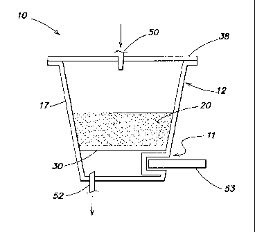
In this illustrative embodiment, the cartridge 10 includes a container 12 that
includes
an interior space 14 having a first chamber 14a and a second chamber 14b that
are separated
by a filter 30. It should be understood, however, that other additional
chambers in the interior
space and/or sub-portions or areas of the first and second chambers, may be
provided in other
embodiments. For example, this embodiment also includes a flow distributor 33
that may
help to distribute incoming liquid across the beverage medium 20, and thus the
flow
distributor 33 may define an area between the flow distributor 33 and the lid
38. Also, it is
possible for the cartridge to have three spaces that are separated by two
filters (e.g., a first
filter separates two portions of a first chamber and a second filter separates
the first and
second chambers), and so on. In another embodiment, the first or second
chamber may be
separated into two portions by a venturi or other feature that introduces air
or liquid into a
beverage. Thus, the first and/or second chambers may be divided or otherwise
separated into
two or more portions or areas by filters, walls, dividers, passageways, and
other features.
Also, it should be appreciated that the cartridge 10 need not include a filter
30, but instead
may be filterless.
If the container 12 includes an opening 13 like that shown in FIGS. 1 and 2,
the
opening 13 may be closed by a lid 38, e.g., a foil and polymer laminate
material that is
attached to a rim 19 of the container 12. (Although in this embodiment the rim
19 is arranged
as an annular flange-like element, the rim 19 may be arranged in other ways.
For example,
the rim 19 may be the top edge of the sidewall 17 without any flange element.)
The container
12 and/or the lid 38 may provide a barrier to moisture and/or gases, such as
oxygen. For
example, the container 12 may be made of a polymer laminate, e.g., formed from
a sheet
including a layer of polystyrene or polypropylene and a layer of EVOH and/or
other barrier
material, such as a metallic foil. Such an arrangement may provide suitable
protection for the
beverage medium 20, e.g., from unwanted exposure from moisture, oxygen and/or
other
materials. It should be understood, however, that the container 12 and/or the
lid 38 may be
made of other materials or combinations of materials, such as biopolymers,
compostable
polymers, paper, foils, etc.
In accordance with an aspect of the invention, the cartridge 10 may include
sonic
receiver 11 (see FIG. 2), such as an acoustically compliant portion that
receives sonic energy
from a sonic emitter which causes the acoustically compliant portion to
vibrate or otherwise
move. This movement of the acoustically compliant portion may introduce sonic
energy into
the interior space 14 to interact with the beverage medium 20, a filter 30 (if
present) and/or
liquid in the interior space 14. The acoustically compliant portion may take
any suitable form,
8
CA 02839293 2013-12-12
WO 2012/174331
PCT/US2012/042586
which may depend on the arrangement of a sonic emitter used to excite the
acoustically
compliant portion. For example, the acoustically compliant portion in this
illustrative
embodiment includes a part of a sidewall 17 arranged to vibrate in response to
acoustic
energy, but an acoustically compliant portion or other sonic receiver 11 may
be arranged at
the bottom 16 and/or lid 38 of the container 12. Thus, the material used to
form the
acoustically compliant portion, the physical shape, thickness or other
characteristics of the
acoustically compliant portion may be carefully arranged to be excited by
acoustic energy so
as to provide a desired sonic energy into the interior space 14. For example,
a portion of the
sidewall 17 may be caused to vibrate by a sonic emitter, which in turn causes
the portion of
the sidewall 17 to create or otherwise introduce sonic energy into the
interior space 14. As
discussed in more detail below, the sonic receiver 11 need not include an
acoustically
compliant section, but rather may be arranged to receive, couple with, or
otherwise interact
with a sonic emitter that introduces sonic energy into the cartridge 10.
Also, although in this embodiment, the sonic receiver 11 is arranged to
cooperate with
a sonic emitter that is located outside of the cartridge 10, the sonic
receiver 11 may be
arranged to cooperate with a sonic emitter located inside of the cartridge 10.
For example, a
sonic probe inserted into the interior space 14 may emit sonic energy which
excites an
acoustically compliant portion of the container. In turn, the excitation of
the acoustically
compliant portion may itself introduce sonic energy into the interior space,
optionally at the
same or a different frequency and/or intensity as the sonic energy emitted by
the probe. This
feature may be exploited to help provide desired acoustic energy in the
interior space,
whether at a desired frequency or amplitude. Moreover, the sonic receiver(s)
11 may be used
make the sonic energy more uniform or otherwise distributed in the interior
space. For
example, whereas a single sonic probe may in some cases form a tunnel or
channel in a
beverage medium because of the concentration of sonic energy in a narrow area,
the sonic
receiver(s) 11 may help to more uniformly distribute sonic energy in the
interior space 14,
thus helping to avoid any tunneling or unwanted concentration of sonic energy
in one or more
areas. Of course, the sonic receiver(s) 11 may be used to help make sonic
energy in the
interior space more uniform or have other desired characteristics by
interacting with a sonic
emitter located outside of the interior space 14.
Although in this illustrative embodiment the container 12 has a generally
frustoconical shape with a flat lid, the container 12 may have a fluted,
conical, or cylindrical
shape, may be in the form of a square or rectangular cup, a domed cup, a
sphere or partial
sphere, or other suitable form, may have a fluted, corrugated, or otherwise
shaped sidewall,
9
CA 02839293 2013-12-12
WO 2012/174331
PCT/US2012/042586
and so on. Also, the container 12 need not necessarily have a defined shape,
as is the case
with some beverage sachets and pods. For example, although the container 12 in
this
embodiment has a relatively rigid and/or resilient construction so that the
container 12 tends
to maintain its shape, the container 12 could be made to have a more compliant
and/or
deformable arrangement, e.g., like a sachet container made from a sheet of
deformable
material. Thus, an interior space defined by the container 12 may be formed
only after the
container material is formed around a beverage medium, filter and/or other
cartridge
components, similar to when two filter paper layers (container material) are
joined together
around a charge of coffee grounds to form a pod or other form of cartridge. In
other
embodiments, the size and/or shape of the cartridge container 12 may be
defined by the brew
chamber in which the cartridge 10 is held.
If provided, the filter 30 may be attached to the lid 38 at a periphery 32
that is spaced
inwardly and away from the rim 19. In addition, the filter 30 may extend from
the periphery
32 at least partially into the interior space 14. The filter 30 may function
to remove materials
over a certain size from a liquid, e.g., may remove coffee grounds from liquid
in the first
chamber 14a, allowing a coffee beverage to pass through the filter 30 to the
second chamber
14b. For example, the filter may include a piece of filter paper that is
arranged to allow a
liquid and dissolved and/or suspended materials of a certain size to pass, yet
prevent
relatively large particles from flowing through the filter. Of course, the
filter 30 may have
multiple stages, e.g., a coarse filter portion that filters out relatively
large particles, followed
by a fine filter portion that filters relatively smaller particles, and so on.
In addition, the filter
may include one or more portions that function to filter liquid passing
through the filter 30,
as well as portions that are impermeable or otherwise restrict flow. Thus, the
filter 30 may
include two or more separate components, if desired. For example, the filter
30 may include
25 a rigid, impermeable plastic sleeve that is attached to the lid 38 at
the periphery 32. At a
location away from the lid 38, a porous filter paper may be attached to the
sleeve. Thus, not
all portions of the filter need be permeable to liquids. The filter 30 may
also have areas with
different permeability, e.g., to help direct flow toward one or more areas of
the filter 30. For
example, regions of the filter 30 near the lid 38 in FIG. 1 may have a
relatively lower
30 permeability as compared to regions further away from the lid 38. This
may help encourage
flow through the beverage medium 20 toward lower regions of the filter 30,
potentially
improving the dissolution of materials in the medium 20 into the liquid.
As described in more detail below, the operation of the filter may be
influenced by
sonic energy in the interior space, e.g., materials that would otherwise not
pass through the
CA 02839293 2013-12-12
WO 2012/174331
PCT/US2012/042586
filter may be caused to pass by the sonic energy. For example, attaching the
filter 30 to the
lid 38 may be useful in some embodiments where a portion of the lid 38
functions as an
acoustically compliant portion. That is, a sonic emitter may excite a portion
of the lid 38, and
since the lid 38 may be connected to the filter 30, both the filter and lid 38
may be excited so
as to introduce sonic energy into the interior space 14. Sonic excitation of
the filter 30 may
help certain materials pass through the filter 30 that would otherwise not
pass through the
filter in the absence of sonic energy. Of course, the filter 30 may be
sonically excited in other
ways, such as by transmitting acoustic energy through the cartridge sidewall
17.
In another aspect of the invention, the filter 30 may also, or alternately,
function to
help prevent the movement of materials from the second chamber 14b to the
first chamber
14a, and/or help position certain beverage materials in the interior space 14
for sonic
treatment. For example, the cartridge 10 may include a beverage medium 20 in
the second
chamber 14b and no beverage medium 20 in the first chamber 14a. In this case,
the filter 30
may help maintain the beverage medium 20 near the bottom 16 and/or sidewall
17. Such
positioning of the beverage medium 20 may help expose the beverage medium to
desired
acoustic energy, e.g., if the energy is introduced from the sidewall 17 and/or
bottom 16. For
example, some beverage media 20, such as powdered drink mixes, can tend to
clump and
may clog or otherwise foul a beverage outlet if not properly dissolved. By
suitably exposing
the drink mix to acoustic energy near the bottom 16 or sidewall 17 of the
cartridge 10, the
drink mix may dissolve or otherwise go into solution more quickly or
effectively than would
otherwise occur. For example, the inventors have discovered that introducing
acoustic
energy into the interior space 14 of a cartridge 10 can cause flow of the
beverage medium 20
and liquid that would not occur in the absence of such energy. In some cases,
the swirling or
other flow can help dissolve a beverage medium or otherwise improve contact of
the medium
with a liquid.
When using the cartridge 10 to form a beverage, the lid 38 and/or the
container 12
may be pierced to introduce liquid into the cartridge and receive beverage
from the cartridge.
(As used herein, "beverage" refers to a liquid substance intended for drinking
that is formed
when a liquid interacts with a beverage medium. Thus, beverage refers to a
liquid that is
ready for consumption, e.g., is dispensed into a cup and ready for drinking,
as well as a liquid
that will undergo other processes or treatments, such as filtering or the
addition of flavorings,
creamer, sweeteners, another beverage, etc., before being consumed.) To
introduce liquid
into the cartridge, for example, as shown in FIG. 3, a portion of the lid 38
generally
circumscribed by the periphery 32 where the filter 30 (if present) is attached
to the lid 38 may
11
CA 02839293 2013-12-12
WO 2012/174331
PCT/US2012/042586
be pierced by an inlet piercing element 50 (e.g., a needle) so that water or
other liquid may be
injected into the cartridge 10. Of course, other piercing approaches may be
used, e.g., where
the filter 30 is attached to the container sidewall 17. Other inlet piercing
arrangements are
possible, such as multiple needles, a shower head, a non-hollow needle, a
cone, a pyramid, a
knife, a blade, etc. A beverage machine that uses the cartridge may include
multiple piercing
elements of the same type or of different types, as the invention is not
limited in this respect.
In another arrangement, a beverage machine may include a piercing element
(such as a spike)
that forms an opening and thereafter a second inlet element (such as a tube)
may pass through
the formed hole to introduce liquid into (or conduct liquid out of) the
container. For those
arrangements in which the cartridge is pierced, a sonic emitter may be
introduced into the
interior space 14. For example, a piercing element 50 (e.g., needle) may
function to pierce
the cartridge, introduce water into the cartridge, and emit sonic energy in
the interior space 14.
Thus, a piercing inlet needle may function as a sonic emitter as well as
provide liquid into the
container. In other embodiments, the lid 38 may be pierced, or otherwise
effectively opened
for flow, by introducing pressure at an exterior of the lid 38. For example, a
water inlet may
be pressed and sealed to the lid 38 exterior and water pressure introduced at
the site. The
water pressure may cause the lid 38 to be pierced or otherwise opened to allow
flow into the
cartridge 10. In another arrangement, the lid 38 may include a valve, conduit
or other
structure that opens when exposed to a suitable pressure and/or when mated
with a water inlet
tube or other structure. In such cases the water (or other liquid) inlet may
still function as a
sonic emitter, although the liquid inlet may not extend into the interior
space 14. In some
arrangements, liquid may be introduced into the cartridge so that all or a
substantial portion
of air or other gas in the cartridge is vented or otherwise removed. This may
help couple
components in the cartridge interior (beverage medium, filter, liquid, etc.)
with a sonic
emitter.
The cartridge 10 may also be penetrated by an outlet piercing element 52
(e.g., a
needle) at a bottom 16 of the container 12, or at a second portion of the lid
38 outside of the
periphery 32 and apart from the inlet opening, or at another portion of the
cartridge 10, such
as the sidewall 17. (The liquid inlet may similarly be located at any suitable
place or places
on the cartridge 10.) As with the inlet piercing arrangement, the outlet
piercing arrangement
may be varied in any suitable way. Thus, the outlet piercing element 52 may
include one or
more hollow or solid needles, knives, blades, tubes, and so on. Such piercing
elements 52
may also function as a sonic emitter, or open a path through which a sonic
emitter may enter
the interior space or otherwise communicate with the cartridge 10.
Alternately, the cartridge
12
CA 02839293 2013-12-12
WO 2012/174331
PCT/US2012/042586
may include a valve, septum or other element that opens to permit beverage to
exit when
liquid is introduced into the cartridge, but otherwise remains closed (e.g.,
to protect the
beverage medium from external conditions such as oxygen, moisture or others).
In such a
case, no piercing element for forming the outlet opening is necessarily
required although may
5 be used, e.g., to allow the valve or other element to open. Also, in this
illustrative
embodiment the piercing element 52 remains in place to receive beverage as it
exits the
opening formed in the container 12 or lid 38. However, in other embodiments,
the piercing
element 52 may withdraw after forming an opening, allowing beverage to exit
the opening
and be received without the piercing element 52 being extended into the
cartridge 10.
10 Although the embodiments described above include a beverage medium 20
only in
the first chamber 14a, or only in the second chamber 14b, the cartridge 10 may
include a
beverage medium (either the same or different) in both chambers or other
portions of the
cartridge. For example, a cartridge may include roast and ground coffee in the
first chamber
14a, and a creamer and sweetener in the second chamber 14b, enabling the
cartridge to form a
cappuccino- or latte-like beverage. In another embodiment, the first chamber
14a may
include coffee grounds and the second chamber 14b may include a hot chocolate
material,
allowing the cartridge to form a mocha-type beverage. Other combinations will
occur to
those of skill in the art, such as leaf tea in the first chamber and a dried
fruit material in the
second chamber, a dried fruit material in the first chamber and
creamer/sweetener in the
second chamber, and so on. In some embodiments, another filter may be
provided, e.g., to
separate beverage media in the second chamber from the fluid outlet. For
example, a filter
may be attached to the lid 38 in an area where an outlet needle pierces the
lid 38 to allow
beverage to exit the cartridge, but only after passing through the additional
filter. The
selection of which beverage media to place in which areas of the cartridge 10
may be made
based on the desired acoustic treatment to be given the beverage media. For
example, certain
hard-to-dissolve beverage media may be located so as to experience a
relatively higher
acoustic energy intensity, whereas other beverage media may be located in
lower intensity
regions. Thus, the cartridge interior space 14 may have regions with different
acoustic
energy characteristics, and those acoustic energy characteristics may be tuned
or otherwise
controlled for particular beverage media or other affects on beverage media.
FIG. 4 shows another illustrative embodiment of a cartridge 10 which in this
case
includes a sonic receiver 11 located at the sidewall 17 of the container 12.
The sonic receiver
11, which may be arranged as a notch, recess or other depression in the
container 12, receives
a sonic emitter 53, which in this instance has the form of an ultrasonic
probe. The depression
13
CA 02839293 2013-12-12
WO 2012/174331
PCT/US2012/042586
11 may have any suitable configuration, e.g., may be tapered so as to closely
fit with a
tapered end of the sonic emitter 53, may include an acoustically compliant
portion that
vibrates in response to sonic energy emitted by the sonic emitter 53, may be
substantially
transparent to sonic energy emitted by the emitter 53 so as to have minimal
attenuation on the
energy, may provide an acoustic coupling between the emitter 53 and the
interior space (e.g.,
the sonic receiver 11 may include a suitable acoustic gel, water or other
substance that
functions as an acoustic coupling medium), etc. In an arrangement where the
depression 11
is configured to vibrate in response to sonic energy from the emitter 53, the
depression 11 or
other feature may function as motion creating structure in the interior space
that causes
beverage medium and/or liquid to move relative to the container 12. Of course,
the shape and
size of the depression may vary, e.g., the depression may have a round,
square, rectangular,
triangular, etc., cross sectional shape, may be sized to interact with the
sonic emitter 53 in a
desired way, may be formed of a different material than other portions of the
container 12
(e.g., may include an element with desired acoustic characteristics that is
molded into the
sidewall 17), and so on. In this case, the sonic receiver 11 is located below
a filter 30 (e.g.,
downstream of the filter 30), but may be arranged to be adjacent to or in
immediate contact
with the beverage medium 20, the filter 30 or other components of the
cartridge 10. (Note
that in this embodiment, the filter 30 is attached to the container 12
sidewall 17, but the filter
30 could be arranged in any way in the cartridge 10, e.g., as part of the
container bottom or
sidewall where a beverage exits.) Sonic energy emitted by the sonic emitter 53
and/or by an
acoustically compliant portion of the cartridge 10 may be in the about 10Hz to
200kHz range
with any suitable intensity, although other frequency ranges and/or
intensities are possible.
By having the sonic emitter extend into a depression in the container 12, the
sonic
emitter 53 may effectively be located inside the cartridge while actually
remaining outside of
the interior space 14. That is, since the depression may extend into the
interior space 14 of
the cartridge 10, the sonic emitter 53 may be located so as to effectively
introduce sonic
energy from within the interior space 14, rather than effectively introducing
the sonic energy
from outside of the interior space. This arrangement may allow the sonic
emitter 53 to
provide may uniform sonic energy to the interior space, may permit sonic
energy to be
concentrated in certain areas of the interior space, and so on. Thus, the
sonic emitter 53 in
arrangements like that in FIG. 4 may be able to function in a way similar to a
sonic emitter
that pierces the cartridge and extends into the interior space, but without
the potential
disadvantages of a piercing probe, such as potential contamination of the
beverage, leaking
from the emitter piercing site, damage to the sonic emitter by contacting the
beverage
14
CA 02839293 2013-12-12
WO 2012/174331
PCT/US2012/042586
medium and/or liquid, etc. In addition, the sonic receiver 11 may focus,
diffuse, redirect, or
otherwise change the way the sonic energy is introduced in the interior space.
For example,
the sonic receiver 11 may receive diffuse sonic energy, and focus that energy
into a suitable
area or zone in the interior space 14.
FIGS. 5 through 16 show various additional embodiments of a cartridge 10
having
different sonic receiver arrangements. However, it should be understood that
these
illustrative embodiments are not intended to provide an exhaustive review of
all possible
ways in which an sonic receiver could be arranged in accordance with aspects
of the
invention. For example, FIG. 5 shows a front view and FIG. 6 shows a bottom
view of a
cartridge 10 that includes a sonic receiver 11 in the form of a notch or step
at a lower right
side of the container 12. FIG. 7 shows a front view and FIG. 8 shows a bottom
view of a
cartridge 10 that includes a sonic receiver 11 in the form of a notch located
at a lower, front
right side of the container 12. FIG. 9 shows a front view and FIG. 10 shows a
bottom view
of a cartridge 10 that includes a sonic receiver 11 in the form of a notch at
a lower front,
center of the container 12. FIG. 11 shows a front view and FIG. 12 shows a
left side view of
a cartridge 10 that includes a sonic receiver 11 in the form of cylindrically-
shaped depression
in the sidewall 17 of the container 12. In this embodiment, the depression
extends into
contact with a filter 30 in the container 12, although the depression need not
contact the filter
30. In the FIGs. 11 and 12 embodiments, as with other embodiments, the sonic
receiver 11
may include more than just the depression. For example, an acoustic coupling
gel or other
substance could be placed in the depression and used to acoustically couple
the sonic emitter
53 with the cartridge interior. In other embodiments, the sonic receiver 11
may include only
the acoustic coupling gel, e.g., applied to the exterior of a cartridge, or
any other suitable
acoustic coupling material, such as water. FIG. 13 shows a front view and FIG.
14 shows a
bottom view of a cartridge 10 that includes a sonic receiver 11 in the form of
a cylindrically-
shaped depression that extends upwardly from the bottom 16 of the container
12. In this
embodiment, the depression does not extend to the filter 30, but the
depression could
optionally extend to the filter 30 or beyond the filter 30 and into a space
above the filter 30.
FIG. 15 shows a front view and FIG. 16 shows a top view of a cartridge 10 that
includes a
sonic receiver 11 in the form of cylindrically-shaped depression that extends
downwardly
from the lid 38 into the interior space of the container 12. The sonic
receiver 11 in this
embodiment may include a cylindrically-shaped cup that is attached to a hole
in the lid 38, or
may be molded or otherwise formed into the lid material.
CA 02839293 2013-12-12
WO 2012/174331
PCT/US2012/042586
Of course, it should be understood that the sonic receivers 11 may be arranged
to have
other sizes, shapes or other configuration details as discussed above.
Moreover, two or more
sonic receivers 11 may be provided, and the sonic receivers 11 may have
different positions
on the container, different sizes, shaped, etc. The sonic receivers 11 may
include acoustically
compliant portions, or not, as desired. In the absence of an acoustically
compliant portion,
the sonic receivers 11 may receive or otherwise couple with a sonic emitter 53
so as to enable
the sonic emitter 53 to introduce sonic energy into the cartridge 10.
In other illustrative embodiments, a sonic receiver 11 may be arranged to be
received
by a sonic emitter 53 rather than to receive the sonic emitter 53. FIGs. 17-19
show a front
view with a cartridge 10 engaged with a sonic emitter 53, a front view of the
cartridge 10
alone, and a bottom view of the cartridge 10, respectively in another
illustrative embodiment.
In contrast to the embodiments shown in FIGs. 5-16, the embodiment in FIGs. 17-
19 has a
sonic receiver 11 arranged to be at least partially surrounded by a sonic
emitter 53. That is,
the lower portion of the container 12 is arranged to form a sonic receiver 11
that is inserted
into a cavity of a sonic emitter 53. A portion of the sonic emitter 53 may
include one or more
beverage outlets 52, although other arrangements are possible, such as where a
beverage exits
from the lid 38 or sidewall 17 of the cartridge 10. With the sonic receiver 11
at least partially
surrounded by the sonic emitter 53, the emitter 53 may transmit sonic energy
into the
cartridge 10 from one or more regions around the exterior of the sonic
receiver 11, including
the bottom 16 of the container 12. In other arrangements, such as that shown
in FIG. 20, the
bottom of the container 12 may extend from the sonic emitter 53, e.g.,
allowing beverage to
exit the container 12 without passing through the sonic emitter 53. Although
the
embodiments in FIGs. 17-20 show the sonic receiver 11 arranged to have a
cylindrical shape,
other shapes are possible, such as a tapered conical shape like that shown in
FIGs. 21-23.
FIGs. 21-23 show a front view with a cartridge 10 engaged with a sonic emitter
53, a front
view of the cartridge 10 alone, and a bottom view of the cartridge 10,
respectively. The
tapered shape of the sonic receiver 11 in this embodiment may allow the sonic
emitter 11 to
fit snugly against the sonic emitter 53, which may enhance the acoustic
coupling between the
sonic emitter 53 and the cartridge interior. Coupling between the sonic
emitter 53 and the
cartridge may be enhanced in this or other embodiments in other ways, such as
by using a
compliant coupling medium (such as a silicone or rubber material as part of
the sonic receiver
11 that interfaces with emitter 53), use of a liquid coupling medium (such as
water), using a
sonic emitter 53 that has a portion that enlarges or reduces in size to clamp
within or around
the receiver 11, providing interlocking corrugations in the cartridge
container and sonic
16
CA 02839293 2013-12-12
WO 2012/174331
PCT/US2012/042586
emitter 53 or otherwise increasing the contact area between the cartridge and
the emitter to
enhance energy transmission, pressing down on the top of the cartridge (or
other cartridge
portion) to help force the cartridge into contact with the emitter 53, etc.
While in the embodiments above, the container 12 tends to remain relatively
stationary, other arrangements may involve a sonic emitter or other vibratory
drive system
that moves the container to a somewhat greater extent so as to cause movement
of beverage
medium, liquid and/or other components in the cartridge. For example, FIGs. 24
and 25
show top perspective and bottom perspective views of a container 12 of a
cartridge 10 that
includes a plurality of sonic receiver features in the form of indentations 11
formed into the
sidewall of the container 12. These indentations 11 may function to
mechanically couple
with a drive system so that the drive system can move the container 12 in an
oscillatory
manner. For example, the drive system may include fins or tabs that engage
with a
corresponding indentation 11 of the container 12 and allow the drive system to
rotate the
container in an oscillatory manner about an axis that is generally
perpendicular to the bottom
16 of the container 12. The container may be oscillated at any suitable
amplitude, such as up
to 10 to 15 degrees, or more (e.g., up to 30 degrees). Oscillating rotation of
the container 12
may cause the indentations 11 to operate as a motion creating structure in the
container 12,
e.g., as agitators that serve to cause movement of the beverage medium, liquid
or other
components in the container 12. For example, the indentations may create
vortices in a liquid
or otherwise cause the liquid to flow or move relative to the container 12. In
some
embodiments, the drive system may oscillate the container 12 at a resonant
frequency of the
indentations 11 so that movement of the indentations relative to other
portions of the
container 12 may be amplified. In other embodiments, the indentations 11 may
be relatively
rigid so that fins or paddles formed by the indentations 11 do not move
appreciably relative to
other portions of the container 12. In some arrangements, the drive system may
oscillate the
cartridge in other ways, such as in a linear up-and-down motion along an axis
perpendicular
to the bottom 16, in a rotary and/or linear manner about an axis parallel to
the plane of the
bottom 16, in a random fashion, and so on. Oscillation of the cartridge may be
performed
before, during or after a time that liquid is provided to the cartridge, e.g.,
"dry" shaking of the
cartridge may help loosen or unpack a beverage medium to make the medium more
easily
wetted by later introduced liquid. Of course, the shape, arrangement, relative
size and other
features of the indentations 11 in FIGs. 24 and 25 may be altered in any
suitable way, such as
having the indentations 11 may be arranged horizontally, in a spiral fashion,
or otherwise.
Moreover, motion creating structures, such as an agitator arrangement, need
not necessarily
17
CA 02839293 2013-12-12
WO 2012/174331
PCT/US2012/042586
be formed by indentations in the container 12. Instead, an agitator may
include one or more
paddles, fingers, fins, tabs or blades that are attached to the container 12,
filter 30 or other
component (such as an insert placed into the container 12) and extend into the
interior space.
Vibratory motion of the container 12 or other cartridge element may cause the
agitators to
interact with the beverage medium and/or liquid to cause motion relative to
the container.
FIGs. 26 and 27 shows a top perspective view and a side view of another
illustrative
embodiment that includes motion creating structure that causes movement of the
beverage
medium and/or liquid in the cartridge relative to the container in response to
oscillatory
movement of a drive system located outside of the closed interior space and
separate from the
beverage cartridge. In this embodiment, the motion creating structure includes
a plurality of
wall elements 61 that are arranged adjacent a periphery of the container 12
and are adapted to
cause net rotary movement of the beverage medium or liquid in response to
oscillatory
rotation of the container 12. That is, the wall elements 61 are arranged in a
suitable zig-zag,
"ratchet," or "ramp and stop" arrangement so that as the container 12 is
rotated clockwise
about an axis that is perpendicular to the bottom 16 (from the perspective of
FIG. 26),
beverage medium and/or other materials may slide along relatively shallow
angle wall
elements 61a. However, when the container 12 is rotated counterclockwise about
the axis
perpendicular to the bottom 16, beverage medium and other materials are pushed
in the
counterclockwise direction by steeper angle wall elements 61b. Thus,
oscillatory rotation of
the container 12 may cause a net rotation of the beverage media and/or other
materials in the
container 12. The wall elements 61 may be provided as features of the
container sidewall 17,
as features of a filter 30, or as part of another element.
In another illustrative embodiment, a motion creating structure may include
one or
more mixing balls that are movable in the interior space of the cartridge
independently of the
container. Movement of the mixing balls may create movement of the beverage
medium or
liquid in the container in response to movement of a container by the drive
system. For
example, several spherical balls may be placed in the first and/or second
chamber 14a, 14b of
the FIG. 1 embodiment. Movement of the container 12 by a drive system (e.g.,
that clamps
the container 12 in a holder that moves in an oscillatory way) may cause the
balls to move in
the container 12, e.g., in rotary, linear up-down or side-to-side, random or
other motions, to
cause movement of the beverage medium and/or liquid in the container. In one
embodiment,
the balls may be magnetic, and the drive system may operated by magnetic
coupling to move
the balls in a suitable way. Thus, the balls may be moved within the container
12 without
movement of the container 12 itself being required. Movement of the balls may
be vibratory
18
CA 02839293 2013-12-12
WO 2012/174331
PCT/US2012/042586
in nature (whether rotary and/or linear) and at any suitable frequency, such
as from 10Hz to
200kHz, as is the case with other embodiments of motion creating structure.
While the term
"balls" is used regarding this embodiment, the "balls" need not be spherical,
but instead may
have a cubic, tetrahedral, cylindrical, irregular or other suitable shape.
One experiment regarding the use of mixing balls was conducted in which a
cartridge
like that in FIG. 24 was coupled to a drive system that rotated the cartridge
about a vertical
axis perpendicular to the bottom of the container. The container was vibrated
at a frequency
of about 10Hz, and at an amplitude of about 30 degrees. The container was
arranged to have
three indentations about 4mm deep arranged in the sidewall of the container.
Vibratory
motion of the container was observed to elicit substantial movement of the
surface of water
placed in the container. Two ball bearings were added to the container, and
the balls were
observed to bounce across the diameter of the container about once per second.
The two ball
bearings were then removed and replaced with two plastic pellets, about 4mm in
diameter.
Vibratory motion of the container also showed agitated motion of water in the
container as
well as bouncing of the plastic pellets across the diameter of the container.
Other configurations of elements that may be added to the interior space of a
cartridge
container are possible. For example, FIGs. 28 and 29 show a container 12 like
that of FIG.
24 and an associated agitator lla that includes a plurality of vertical
paddles that are
connected together by peripheral band elements. In this embodiment, the
paddles are
arranged to fit over indentations 11 in the container 12, e.g., so that
rotation or other
movement of the container 12 may be transmitted to the agitator 11a, but other
arrangements
are possible. For example, an agitator lla like that in FIG. 29 may be
provided with an
interference fit inside of a container 12, inside of a filter 30 (e.g., such
as a filter 30 like that
in FIG. 1) and/or in other ways. Arranging the motion creating structure as an
insert to a
container 12 may ease manufacturing of the motion creating structure, as well
as allow
customization of motion creating structure for different types of beverage
media. For
example, some beverage media, such as drink mixes, may require higher
amplitude or
otherwise more vigorous motion to achieve a desired result, whereas other
beverage media,
such as tea leaves, may require little or no motion at all to achieve a
desired result. Thus, for
containers having a drink mix one type of motion creating insert may be placed
in the
container, whereas for containers having different type of beverage medium,
another type of
motion creating insert may be placed in the container (or no insert at all).
FIGs. 30 and 31 show another illustrative arrangement in which an agitator lla
is
received in a container 12 like that of FIG. 24. In this embodiment, the
agitator 1 la includes
19
CA 02839293 2013-12-12
WO 2012/174331
PCT/US2012/042586
scraper portions 111 between indentation engagement portions 112. As can be
seen in FIG.
30, the indentation engagement portions 112 fit over and engage with
indentations 11 of the
container 12. As a result, movement of the container 12 can be translated to
the agitator lla.
In some embodiments, the scraper portions 111 may move at least somewhat
independently
of the indentation engagement portions 112 so that the lowermost part of the
scraper portions
111 can scrape, contact or otherwise agitate materials near the bottom 16 of
the container 12.
This arrangement may be useful, for example, when seeking to help ensure that
beverage
media near the bottom of the container 12 is fully dissolved or otherwise
suitably interacts
with water or other liquid in the container 12. In some cases, the agitator
lla may be excited
at a resonant frequency of the scraper portions 111 so that the scraper
portions 111 move with
an enhanced amplitude relative to the container 12 and/or other portions of
the agitator 11a,
such as the indentation engagement portions 112.
While several embodiments above have been described in relation to motion of a
cartridge container 12 about an axis generally perpendicular to its bottom 16,
it should be
appreciated that motion creating structure may cause suitable motion of
beverage media,
liquid or other components in a cartridge in response to other types of
motion. For example,
FIGs. 32 and 33 show a way in which a cartridge container 12 like that in FIG.
24 may be
moved in a dilatational way, e.g., so that as one pair of opposed portions of
the container
sidewall 17 move towards each other, another pair of opposed portions of the
sidewall 17
may move away from each other, and vice versa. Thus, the container sidewall 17
may
oscillate so as to change the shape of the container 12, albeit slightly in
some embodiments.
Such movement may cause some agitator or other motion creating structure
arrangements to
cause movement of materials in the container 12. For example, the agitator lla
in FIGs. 30
and 31 may be arranged to move the scraper portions 111 relative to the
container bottom 16
in response to dilatational movement like that shown in FIGs. 32 and 33. Of
course, other
motion creating structure may be used with dilatational vibration like that
shown in FIGs. 32
and 33, or other dilatational vibration such as where a container 12 like that
in FIG. 24
oscillates in vertical dimension, as opposed to, or in addition to, a
horizontal dimension like
that in FIGs. 32 and 33. FIGs. 34 and 35 show a schematic view of another
arrangement in
which motion creating structure in a cartridge container 12 includes a
flexible beam 11 that
extends from one side of the container 12 to the other. As the container 12 is
moved
dilatationally in a horizontal dimension, the beam 11 may alternate between a
generally
straight or other starting arrangement and a bowed or other displaced
arrangement. As will
CA 02839293 2013-12-12
WO 2012/174331
PCT/US2012/042586
be understood, movement of the beam 11 may operate to mix or otherwise cause
movement
of materials in the container 12.
FIGs. 36 and 37 show another illustrative embodiment that is somewhat similar
to that
shown in FIGs. 34 and 35. In this embodiment, an agitator includes a drive
beam 1 la and a
paddle 11b. The drive beam lla extends across the container 12, but unlike the
arrangement
in FIG. 34, the drive beam lla has a "Z" shape such that two long and
generally straight legs
are offset from each other near the center of the container 12 and are joined
together by a
short leg. The paddle 1 lb is connected to the short leg so that as the two
long legs are moved
toward and away from each other, the short leg and the attached paddle 1 lb
rotate about a
generally vertical axis. As will be understood, the amplitude of dilatational
vibration, the
length of the short leg, the size of the paddle and/or other features may be
suitably arranged
to cause desired movement in the container 12.
While in many of the embodiments above, motion creating structure may be
contained entirely inside of a container 12, in one aspect of the invention,
motion creating
structure may include a first portion in the interior space of a container and
a second portion
outside of the interior space. This arrangement may allow a drive system to
directly contact
the second portion of the motion creating structure and allow the motion of
the drive system
to be transmitted to the first portion. Such an arrangement may allow for more
efficient
transfer of motion from a drive system to motion creating structure in a
cartridge. FIG. 38
shows a perspective view of one embodiment in which motion creating structure,
e.g., an
agitator, includes a first portion lla in the container 12 and a second
portion 1 lb outside of
the container 12. In this embodiment, the first portion lla of the agitator
includes a "spoon"
type shape that may be moved by a drive system moving the second portion 1 lb
up and down
(as shown by the arrows), side to side, or in other ways. In this arrangement,
the first portion
lla is located in a space defined by a filter 30, but other arrangements are
possible, such as
those that do not include a filter 30. In another embodiment of FIG. 39, the
first portion lla
includes a ring or hoop shape that extends around a periphery of a filter 30.
Thus, when a
second portion 1 lb is moved, the first portion lla may engage with and move
the filter 30,
e.g., to cause movement of beverage media inside of the filter. In another
illustrative
embodiment of FIG. 40, the first portion lla of the motion creating structure
may function as
a filter 30 as well, e.g., including a plurality of suitably sized, shaped and
arranged holes in a
cup. Alternately, the first portion lla may function as a flow diverter, e.g.,
slowing,
spreading or otherwise modifying flow of liquid and/or other materials in the
cartridge. In
another embodiment shown in FIG. 41, the first portion lla of an agitator may
include a
21
CA 02839293 2013-12-12
WO 2012/174331
PCT/US2012/042586
plurality of rings or other orifices, e.g., to help with emulsification or
other treatment of
beverage media or other components in a containers. FIG. 42 shows yet another
embodiment
that includes three (or more) "fingers" or other elements that may be used for
mixing,
assisting in wetting of beverage media, and/or other functions. FIG. 43 shows
another
illustrative embodiment in which a first portion includes a ring with inwardly
extending fins.
Oscillatory movement of the first portion lla may cause the fins to vibrate
back and forth (as
shown by the arrows). As with any embodiments, motion creating structure may
be driven so
as to cause one or more portions of the structure to vibrate at a resonant
frequency, which
may amplify or otherwise enhance the effect of the motion creating structure.
FIG. 44 shows another embodiment of motion creating structure that includes a
first
portion lla in the cartridge interior space, and a pair of portions 1 lb that
extend outside of
the interior space. This arrangement may allow a drive system to engage both
portions 1 lb
of the motion creating structure, which may allow the drive system to more
efficiently or
otherwise effectively cause motion of the first portion 11a, e.g., the
lowermost bottom portion
of the motion creating structure. In this illustrative embodiment, the "V"
shaped sides of the
first portion lla are corrugated to provide additional stiffness to these
parts of the motion
creating structure. For example, FIG. 45 shows a similar arrangement for a
motion creating
structure, with a difference being that the depending sides of the "V" are not
corrugated.
Testing has found that movement of the lowermost flat portion between the "V"
sides in the
FIG. 44 embodiment moves up to three times more than the corresponding flat
portion in the
FIG. 45 embodiment. It is believed that the higher stiffness of the "V" sides
in the FIG. 45
embodiment due to the corrugations provides this result. The first portion lla
may be
arranged to focus acoustic energy produced by the "V" sides in the interior
space, e.g., in a
region between the "V" sides. This may help create a relatively high energy
focal zone,
potentially sufficient to cause cavitation in a liquid. In the FIG. 45
embodiment, a reflector
11c may be provided to help intensify acoustic energy in the interior space
and/or help create
or maintain a focal zone of energy.
Cartridges in accordance with aspects of the invention may be used with any
suitable
beverage machine. For example, FIG. 46 shows a perspective view of a beverage
forming
apparatus 100 that may be used to form any suitable beverage, such as tea,
coffee, other
infusion-type beverages, beverages formed from a liquid or powdered
concentrate, hot or
cold drinks, etc. In this illustrative embodiment, the apparatus 100 includes
an outer frame or
housing 6 with a user interface 8 that the user may operate to control various
features of the
apparatus 100. A beverage cartridge 10 may be provided to the apparatus 100
and used to
22
CA 02839293 2013-12-12
WO 2012/174331
PCT/US2012/042586
form a beverage that is deposited into a cup or other suitable receptacle that
is placed on a
drip tray 9 or other support, if any. The cartridge 10 may be manually or
automatically
placed in a cartridge receiving portion defined by first and second portions 3
and 4 of the
beverage forming apparatus 100. For example, by lifting a handle 5, the user
may move the
first and second portions 3 and 4 to an open position to expose a suitably
shaped area in
which the cartridge 10 may be placed. After placement of the cartridge 10, a
handle 5 or
other actuator may be moved in a manual or automatic fashion so as to move the
first and
second portions 3 and 4 to a closed position (shown in FIG. 46), thereby at
least partially
enclosing the cartridge 10 within a brew chamber. It should be understood,
however, that the
cartridge 10 may be received in any suitable way by the apparatus 100, as the
way in which
the apparatus 100 receives or otherwise uses the cartridge 10 is not critical
to aspects of the
invention.
Once the cartridge 10 is received, the beverage forming apparatus 100 may use
the
cartridge 10 to form a beverage. For example, one or more inlet needles 50
(see FIG. 3 or 4)
associated with the first or second portion 3, 4 may pierce the cartridge 10
so as to inject
heated water or other liquid into the cartridge 10. In one aspect of the
invention, sonic
excitation of the beverage medium, liquid or other component in the cartridge
may be used
together with pulsatile introduction of liquid into the cartridge. It has been
found in some
embodiments that pulsed flow of liquid into the cartridge together with sonic-
induced
movement can be very effective in helping dissolve beverage media, such as
powdered
materials. The pulsed flow may be arranged in any suitable way, such as one or
more
introductions of liquid into the cartridge per second at a volume of 1% or
more of the total
beverage for each intermittent liquid introduction (e.g., slugs of water
having a volume of
about 3-5ml may be introduced once per second to form a 300m1 beverage.) In
some
embodiments, individual slugs of liquid may be introduced at a jet or other
relatively high
speed way, e.g., to help cause movement of the beverage medium. The first or
second
portion 3, 4 may also include one or more outlet needles or other elements 52
to puncture or
pierce the cartridge 10 (as needed) at an outlet side to permit the formed
beverage to exit the
cartridge 10. If the inlet and outlet are provided at a same side of the
cartridge 10, such as at
the lid 38 shown in FIG. 3, the cartridge 10 may be oriented during beverage
formation so
that the lid 38 is below the bottom 16 (e.g., with the lid 38 facing generally
downward) or is
otherwise oriented so that beverage can be suitably removed from the cartridge
10.
FIG. 47 shows a schematic block diagram of various components included in a
beverage forming apparatus 100 in one illustrative embodiment, such as that in
FIG. 46.
23
CA 02839293 2013-12-12
WO 2012/174331
PCT/US2012/042586
Those of skill in the art will appreciate that a beverage forming apparatus
100 may be
configured in a variety of different ways, and thus aspects of the invention
should not be
narrowly interpreted as relating only to one type of beverage forming
apparatus. Water or
other liquid from a storage tank 110 may be provided via a supply conduit 111
to a pump 112
(such as a centrifugal pump, piston pump, solenoid pump, etc.), which pumps
the liquid via a
pump conduit 115 to a metering tank or chamber 118. Operation of the water
pump 112 and
other components of the apparatus 100 may be controlled by a controller 130,
e.g., including
a programmed processor and/or other data processing device along with suitable
software or
other operating instructions, one or more memories (including non-transient
storage media
that may store software and/or other operating instructions), temperature and
liquid level
sensors, pressure sensors, input/output interfaces, communication buses or
other links, a
display, switches, relays, triacs, or other components necessary to perform
desired
input/output or other functions. The metering tank 118 may be filled with a
desired amount
of liquid by any suitable technique, such as running the pump 112 for a
predetermined time,
sensing a water level in the metering tank 118 using a conductive probe sensor
or capacitive
sensor, detecting a pressure rise in metering tank 118 when the liquid fills
the tank, or using
any other viable technique. For example, the controller 130 may detect that
the metering tank
118 is completely filled when a pressure sensor detects a rise in pressure
indicating that the
water has reached the top of the metering tank 118. Water in the tank may be
heated, if
desired, by way of a heating element 123 whose operation is controlled by the
controller 130
using input from a temperature sensor or other suitable input. Water in the
metering tank 118
may be dispensed via a metering tank conduit 119 to a brew chamber 120 or
other beverage
forming station. The brew chamber 120 may include any beverage making
ingredient, such
as ground coffee, tea, a flavored drink mix, or other substance, e.g.,
contained in a cartridge
10. Liquid may be discharged from the metering tank 118 by pressurizing the
metering tank
with air provided by an air pump 121 that causes the liquid to be discharged
out of a tube 117
and into the metering tank conduit 119. Completion of the dispensing from the
metering tank
118 may be detected in any suitable way, such as by detecting a pressure drop
in the metering
tank 118, by detecting a water level change in the metering tank 118, use of a
flow meter, or
using any other viable techniques. Liquid may alternately be discharged from
the metering
tank 118 by the pump 112 operating to force additional liquid into the tank
118, thereby
displacing water out of the tank 118 and to the brew chamber. A flow sensor or
other
suitable device may be used to determine the amount of liquid delivered to the
tank 118, and
thus the amount of liquid delivered to the brew chamber. Alternately, the pump
12 may be a
24
CA 02839293 2013-12-12
WO 2012/174331
PCT/US2012/042586
piston-type or metering pump such that a known volume of liquid may be
delivered from the
pump 112 to the tank 118, thus causing the same known volume to be delivered
to the brew
chamber 120. Liquid may be introduced into the cartridge 10 at any suitable
pressure, e.g., 1-
2 psi or higher.
The beverage forming apparatus 100 may also include one or more sonic emitters
53
to interact with the cartridge 10 during beverage formation. The sonic emitter
53 may be
moveable so as to move into contact with or otherwise suitable position
relative to the
cartridge 10 in the brew chamber 120, or may be stationary with the cartridge
10 moved into
suitable position relative to the emitter 53. The sonic emitter 53 may include
any suitable
components, such as one or more piezoelectric elements that function as an
ultrasonic
transducer, an electromagnetic device (such as a speaker driver) that produces
ultrasonic
energy, a mechanical device that produces sonic energy (such as a motor driven
rod or other
component that is caused to vibrate at a suitable frequency of 10Hz to 100kHz
or more), and
so on. The sonic emitter 53 may also include one or more acoustic coupling
components,
such as a rubber gasket, water bath or other element that helps to couple
acoustic or other
vibrational energy to the cartridge 10. The controller 130 may also include a
suitable control
or driver circuit to cause the sonic emitter 53 to emit sonic energy. In one
embodiment, the
sonic emitter 53 can include an ultrasonic vibratory transducer such as a
Model XL-2000
model with probe specifications of a CML-4 with a P-1 microprobe, manufactured
and
obtained from Qsonica, LLC. This ultrasonic transducer operates at frequencies
of about
22kHz.
The beverage forming apparatus (e.g., the controller 130) may include a RFID
tag
reader or other arrangement suitable to identify a cartridge or type of
cartridge and control
apparatus operations (such as operation of the sonic emitter 53, water
temperature, water
volume, etc.) based on the cartridge or type of cartridge. For example,
cartridges may
include an RFID tag, barcode, alphanumeric text, a color code, or other
machine readable
indicia that the controller 130 can read or otherwise identify. Based on the
indicia (which
may include a serial number, an alphanumeric text string, a name or type of
beverage
medium in the cartridge, a type of drink to be formed using the cartridge,
etc.), the controller
130 may vary the apparatus operation to adjust the type of beverage produced.
In some
embodiments, the indicia may be used to determine whether, and to what extent,
a sonic
emitter or other drive system should be operated to introduce sonic energy to
the cartridge.
As mentioned above, some beverage types may require more or less (or no) sonic-
energy
induced movement for beverage formation, and the controller 130 may operate
the sonic
CA 02839293 2013-12-12
WO 2012/174331
PCT/US2012/042586
emitter 53 accordingly. In addition, or alternately, cartridges could be made
to accommodate
different sonic excitement of beverage media, etc., e.g., by providing
differently sized,
shaped or otherwise configured motion creating structure for different types
of cartridges.
Thus, in some embodiments, the sonic emitter 53 may always operate in the same
way, but
control of whether sonic-induced motion is provided to the cartridge interior
may be made by
the presence, absence or other characteristics of motion creating structure
associated with the
cartridges. For example, in embodiments where no vibratory motion is desired
in a cartridge
interior, no motion creating structure may be provided. In other embodiments
where
vibratory motion is desired, motion creating structure may be provided that
couples with the
sonic emitter to transmit sonic energy to the interior space. However, in both
cases, the sonic
emitter may be operated in the same way when using both types of cartridges.
In other aspects of the invention, methods for forming a beverage using a
cartridge
and sonic energy are provided. Some embodiments in this regard may provide one
or more
of the following advantages: (1) increasing the speed of forming a beverage,
(2) increasing
the strength of a beverage, (3) producing different qualities of beverages,
(4) increasing the
degree of extraction of a beverage material during brewing, and/or (5)
enabling the use of
beverage media that would otherwise be unusable for a given application (e.g.,
allow the use
of a fine powdered material that, in the absence of sonic-induced movement,
would not be
expected to fully dissolve into liquid introduced into a cartridge). In one
embodiment shown
in FIG. 48 a method for forming a beverage includes, in step S10, providing a
beverage
cartridge arranged for use in a beverage forming machine to make a beverage.
The cartridge
may include a container having a closed interior space and a beverage medium
located in the
interior space. As discussed above, the cartridge may take any of a variety of
forms, e.g.,
may be permeable or impermeable, may have a sachet, pod, or other form, may
include
relatively rigid and/or flexible elements, may be arranged to maintain a
specific shape or
shapeless, may include a filter or not, if a filter is included, it may be
located in the interior
space of the cartridge and/or at the cartridge exterior (e.g., like that in
many beverage pods),
and so on.
In some embodiments, the cartridge may include a sonic receiver attached to or
otherwise associated with the container and arranged to transmit vibratory or
other sonic
energy from a sonic emitter located outside of the closed interior space into
the interior space
for interaction with the beverage medium. For example, the cartridge may
include an
acoustically compliant portion that is arranged to vibrate in response to
exposure to acoustic
energy so that the acoustically compliant portion introduces sonic energy
having a desired
26
CA 02839293 2013-12-12
WO 2012/174331
PCT/US2012/042586
frequency and/or intensity into the interior space of the cartridge. The
acoustically compliant
portion may have a physical structure, material composition or arrangement, or
other features
that allow the acoustically compliant portion to operate as desired.
In other embodiments, a sonic receiver of the cartridge may include a notch,
groove,
recess, or other depression in a portion of the container, such as a sidewall,
bottom, lid or
other part of the cartridge. (It should be understood that a cartridge need
not include a bottom,
sidewall and/or lid. Some embodiments, such as a spherically shaped container,
may not
have any defined bottom or lid, for example.) The notch, groove, etc. may
engage with a
sonic emitter or other vibratory drive system so as to couple at least a
portion of the cartridge
with the drive system. In other embodiments, the sonic receiver may include a
protrusion or
other portion that is received by a sonic emitter, e.g., a portion of the
container may be
received into a hole, recess or other depression of the sonic emitter. The
sonic receiver may
be transparent, or substantially transparent to acoustic energy emitted by the
sonic emitter,
allowing the sonic emitter to introduce sonic energy directly into the
cartridge. In other
arrangements, the sonic receiver may transmit sonic energy into the interior
space of the
cartridge.
In step S20, liquid may be introduced into the closed interior space of the
cartridge.
Any suitable liquid may be introduced into the interior space, such as water,
filtered,
carbonated or otherwise processed water, milk, juice, coffee extract, etc.
Introduction of the
liquid may be done in any suitable way, such as by piercing the container,
e.g., with a needle,
and injecting liquid into the closed interior space. In other embodiments,
pressurized liquid
may be applied to the exterior of the cartridge container to cause one or more
openings to
form so as to admit the liquid. In other embodiments, the liquid may be simply
poured into
the cartridge, e.g., where a lid of the cartridge is removed to allow water to
be poured into the
cartridge. The liquid may be introduced under pressure, e.g., 1-2 psi or more,
and may be
introduced at any suitable flow rate and along with any other suitable
materials, such as air
bubbles entrained in the liquid, solid materials suspended in the liquid, etc.
In step S30, sonic energy may be introduced into the closed interior space of
the
cartridge while liquid introduced into the closed interior space is present in
the cartridge.
Sonic energy may be introduced in any of the ways described above, including
inserting an
ultrasonic emitter probe into the cartridge, positioning a sonic emitter in
contact with or
suitably near a sonic receiver of the cartridge, and so on. Sonic energy may
be transmitted
directly through the container, or may be introduced by an acoustically
compliant portion of
the cartridge that vibrates in response to exposure to sonic energy and by the
vibration
27
CA 02839293 2013-12-12
WO 2012/174331
PCT/US2012/042586
introduces sonic energy into the interior space. In some embodiments, a sonic
emitter may
cause movement of a motion creating structure in the cartridge to cause
movement of the
beverage medium in the closed interior space. For example, a vibratory drive
system may
move a part of the cartridge, which causes a motion creating structure to move
within the
interior space of the cartridge, thereby causing motion of the beverage
medium, liquid in the
interior space, a filter in the cartridge, etc.
In step S40, a beverage may be formed by simultaneous interaction of the
liquid and
sonic energy with the beverage medium. This step may include a variety of
different features,
such as causing materials to pass through a filter in the cartridge that would
not pass through
the filter in the absence of the sonic energy. For example, the beverage may
be formed with a
higher level of dissolved and/or suspended materials than would be present in
the absence of
the sonic energy. In other embodiments, the beverage may have a turbidity
and/or a level of
total dissolved solids that is higher than would be present in the absence of
the sonic energy.
In yet other embodiments, the step of forming a beverage may include causing
flow of
beverage medium and liquid in the interior space by exposing the interior
space to the sonic
energy. For example, while introducing liquid into the interior space
typically will cause
flow of beverage medium and liquid in the interior space, the sonic energy
introduced into the
cartridge may cause additional flow or other movement of beverage medium and
liquid in the
interior space. Such additional movement may help dissolve materials in the
beverage
medium and/or otherwise cause faster or more efficient extraction of materials
from the
beverage medium.
The inventors have performed experiments described below. These experiments
are
not intended to limit the scope of aspects of the invention, but rather
provide support for
some of the aspects of the invention described and claimed herein.
Example 1: 18 K-Cup brand cartridges of a decaffeinated Arabica medium roast
and
ground coffee were obtained from standard product-for-sale by Green Mountain
Coffee
Roasters, Inc. (GMCR) under the trade name "Breakfast Blend Decaf." Nine of
the
cartridges were brewed at the 192 deg F water temperature at the 8 ounce
setting on a
"Platinum" Single Cup Coffee Brewer which is also sold by GMCR. These nine
brewed
samples are the "control".
The next nine samples were also brewed on the Platinum brewer, but were
subjected
to externally-applied sonic energy. To apply the energy during brewing, the
brewer was
modified by removing the plastic housings surrounding the cartridge brew
chamber, such that
28
CA 02839293 2013-12-12
WO 2012/174331
PCT/US2012/042586
the sidewall of the cartridge was exposed. A "Sonicare Toothbrush"
manufactured by Philips
was obtained from standard product-for-sale at a retail store. The toothbrush
was assembled
with the brush head in place. During brewing, the back of the head of the
brush (not the
bristles) was pressed against the exposed wall of the cartridge and the power
was switched
"on". In this instance, there was no notch or other depression in the
cartridge. The sonically-
vibrating head was kept pressed against the cartridge during the entire brew
cycle. The wall
of the cartridge vibrated due to the action of the sonic vibrations of the
brush head, as
evidenced by simply touching and sensing the vibrations with a finger. The
nine sonically-
brewed samples are the "test".
Both the control and the test brewed coffee samples were analyzed for
turbidity
measurements in "NTU' s". "NTU" units are Nephelometric Turbidity Units. These
were
measured using a HACH model 2100N Turbidimeter, available from Hach Company.
The
NTU values were measured on the coffee about 5 minutes after brewing the
coffee.
The results of the NTU measurements are:
Control: 37.7, 32.8, 34.4, 39.4, 31.2, 33.8, 34.0, 47.0, 31.3
Test: 63.9, 62.1, 49.5, 46.9, 41.8, 59.8, 57.3, 66.7, 54.7
Control Mean: 35.7
Test Mean: 55.9
One skilled in coffee technology will recognize that the coffee became more
turbid as
sonic power was externally applied. One skilled in coffee technology would
recognize that
increased turbidity is an indicator of increased coffee strength, and can be
caused by
suspended solids, oils and other "colloidal" substances. Surprisingly, the
application of sonic
energy appears to have enhanced the ability of colloidal substances to pass
through a coffee
filter such as a paper coffee filter. The inventors can postulate that
possibly the sonic energy
modified the colloidal substances and/or agitated the beverage materials to
release the
colloidal material and pass them through the filter.
Example 2:
6 K-Cup brand cartridges each including about 12 grams of dark roast and
ground
coffee were obtained from standard product-for-sale by Green Mountain Coffee
Roasters, Inc.
(GMCR) and were brewed at the 192 deg F water temperature at the 8 ounce
setting on a
"B80" Coffee Brewer sold by Keurig, Incorporated. During brewing, a sonic
emitter in the
form of a "sonicator" Model XL-2000 model with probe specifications of a CML-4
with a P-
1 microprobe, manufactured and obtained from Qsonica, LLC, was inserted
through the lid of
each cartridge and into the interior space about 0.25 inches. The total brew
time for all power
29
CA 02839293 2013-12-12
WO 2012/174331
PCT/US2012/042586
levels was about 35 seconds. The sonic energy was applied starting at about 5
seconds after
the water flow was initiated and then stopped at the very end of the 35 second
period. Each
cartridge was brewed while the sonicator was provided with different power
levels, i.e., 0, 5,
7, 11. 15 and 40 watts. Turbidity measurements (in "NTU" units) of the
resulting coffee
solutions were measured using a HACH model 2100N Turbidimeter, available from
Hach
Company about 5 minutes after brewing the coffee. "Total Dissolved Solids"
(TDS)
measurements were also made of the same brewed coffee samples. These
measurements
were also taken at about 5 minutes after brewing the coffee using a model
Ultrameter II 6PII
CE, available from Myron L Company. The results of the NTU and TDS
measurements for
the six cartridges were about:
NTU: 70, 140, 210, 290, 350, 410
TDS: 1.130, 1.110, 1.125, 1.112, 1.122, 1.190
Watts: 0, 5, 7, 11. 15,40
One skilled in coffee technology will recognize that the coffee became more
turbid as
sonic power was increased. One skilled in coffee technology will also
recognize that
increased turbidity is an indicator of increased coffee strength, and can be
caused by
suspended solids, oils and other "colloidal" substances. Brewed coffee with
sonic energy
application was tasted relative to coffee in which no sonic power was applied,
and was found
to taste stronger when such sonic energy was applied. Surprisingly, the
application of sonic
energy appears to have enhanced the ability of colloidal substances to pass
through a coffee
filter such as a paper coffee filter. One skilled in coffee technology
recognizes that paper-
filtered coffee can suffer from weak taste due to the lack of such colloidal
or turbidity-
causing substances. The inventors can postulate that possibly the sonic energy
modified the
colloidal substances and/or agitated the beverage materials to release the
colloidal material
and pass them through the filter.
Regarding TDS, at the highest power setting between 40 and 45 watts, a
dramatic
increase in dissolved solids was achieved (1.190 % dissolved solids) versus
1.130 %
dissolved solids when no power was applied. Surprisingly, lower levels of
dissolved solids
were achieved at power settings below 20 watts. A visual examination of the
bed of coffee
grounds after sonic brewing (by peeling the lid from the cartridge) showed
that a channel or
tunnel was formed through the bed, most likely caused by the sonic energy
emanating from
the tip of the probe. The inventors can postulate that the open channel or
tunnel caused a
portion of the water to more quickly pass through the bed of coffee and thus
drop the overall
extraction efficiency of dissolved solids. Yet, even though a drop in
extraction efficiency of
CA 02839293 2013-12-12
WO 2012/174331
PCT/US2012/042586
dissolved solids was observed, the extraction/suspension of turbidity-
effecting substances
was not, which is an entirely unanticipated result.
Example 3
A "Platinum" Single Cup Coffee Brewer sold by Keurig, Incorporated was used to
brew beverages using several different types of beverage media. Each cartridge
was arranged
with a frustoconical cup container, a foil laminate lid and, for some beverage
types, a filter
attached near the top rim of the cartridge. The brewer was modified to move
the cartridge
receiver/brew chamber outside of the brewer for attachment to the cone of a
loudspeaker (i.e.,
a voice coil actuator) by a simple linkage. The loudspeaker was driven by a
signal generator
via an amplifier, allowing the cartridge and receiver to be vibrated with a
range of
frequencies and amplitudes. With different configurations of the loudspeaker
and linkage,
the cartridge and receiver could be vibrated on a horizontal axis, a vertical
axis, or in a rotary
manner about the vertical axis.
The brewer is designed to provide a flow with an approximately constant
pressure.
For most beverage types, an 8oz volume of water is delivered through the
cartridge in
roughly 35 seconds. In some experiments it was found that vibrating the
cartridge could
result in an increased resistance to flow in the cartridge, possibly due to
the cartridge filter
filling up with fine particles. This would result in the brewer delivering
water at a reduced
flow rate. In these cases, a peristaltic pump was applied to the tubing from
the brewer to the
inlet of the cartridge receiver to ensure a constant flow rate. As such, the
results described in
the following sections were achieved under essentially constant flow rate
conditions.
A number of other conditions were controlled to ensure that the observed
effects were
due solely to the vibration:
The temperature of the brewed beverage was measured as soon as it was
delivered, to check for minimal variation.
kk The brewer was filled using "soft water," prepared from
distilled water by
adding a fixed concentration of salts.
a' The K-cups were hand-filled with a weighed amount of beverage
medium, to
ensure a constant fill weight.
Various measurements were made on the beverages produced:
^ TDS (ppm KC1 at 20 degrees C) was measured using a COM-100 conductivity
31
CA 02839293 2013-12-12
WO 2012/174331
PCT/US2012/042586
meter from HM Digital. The reading was corrected for the temperature of the
delivered
brew (also measured by the COM-100) to give equivalent TDS at 20 C.
Turbidity was measured using 2100N Turbidimeter from Hach.
Brix (refractive measurement of TDS) was measured using a DR-100L
refractometer from Bellingham & Stanley Ltd.
Coffee testing
Cartridges containing Green Mountain Coffee Roasters, Inc. (GMCR) "Dark Magic"
roasted coffee grounds were used. Five cartridges were run with no vibration,
where the
volume of beverage produced was about 8 ounces. The results are shown below:
Fill Brew Turbidity TDS Brix
weight time (s)
(gm)
14.69 33 24.7 1181 1.4
14.92 32 29.9 1192 1.5
14.77 33 37.3 1212 1.6
14.89 32 30.2 1222 1.5
14.8 32 33.4 1242 1.6
Another five cartridges were run with horizontal vibration at 20Hz frequency
at
3.5mm amplitude, and the results are shown below:
Fill Brew Turbidity TDS Brix
weight time (s)
(gm)
14.54 33 46.1 1151 1.5
14.58 32 46.5 1157 1.3
14.77 33 46.8 1199 1.2
14.5 32 48.3 1183 1.2
14.64 32 44.7 1163 1.4
The vibration clearly increased the turbidity of the brewed coffee, with only
a slight
reduction in dissolved solids (as measured by TDS or Brix).
32
CA 02839293 2013-12-12
WO 2012/174331
PCT/US2012/042586
Cocoa powder testing
Cartridges containing cocoa powder were used. One difficulty in forming a
beverage
using cocoa powder in a beverage cartridge is achieving adequate dissolution
of the powder,
which can result in residual cocoa powder, either dry or partly dissolved,
left in the cartridge
at the end of brewing.
Fifteen total cartridges containing cocoa powder were used to form a beverage
where
the volume of beverage produced was about 8 ounces. Five of the cartridges
were used
without applying vibratory energy to the cartridges. Five other cartridges
were used while
applying vibratory energy at 20Hz with an amplitude of 0.8mm, and the
remaining five
cartridges were used while applying vibratory energy at 20Hz with an amplitude
of 3.5mm.
Two of the cartridges used without vibratory energy included a relatively
large amount of
residue, while the other three cartridges were generally residue free. Of the
five cartridges
used with vibration applied to them at the 0.8mm amplitude, none showed any
solid residues,
and two show residual water with a slight taint of residual, dissolved cocoa.
Of the five
cartridges used with vibration applied to them at the 3.5mm amplitude, none
showed any
solid residues, one showed residual water with some dissolved cocoa and one
showed
residual water with a slight taint of dissolved cocoa.
In another experiment, cartridges containing cocoa powder and two steel ball
bearings
(about 4mm) were vibrated horizontally at a frequency of about 20Hz and an
amplitude of
about 0.6mm to produce an approximately 8 ounce beverage. Little or no cocoa
powder was
observed to remain in the cartridges after use.
Skimmed milk powder testing
Natural milk powders are not typically used in cartridges: the powders tend to
form
lumps under the application of hot water and these lumps do not pass through
the filter. As a
result, synthetic creamers are often used instead. However, these can be
difficult and time
consuming to formulate so as to both provide a good taste and to pass through
the filter.
Five cartridges containing natural milk powder were tested under each of four
conditions: no vibration, 100Hz vibration at low amplitude, 20Hz vibration at
low and high
amplitude. The table below shows the mean brew time and mean mass of residue
in the
cartridge after leaving the cartridge to dry, the mean TDS (ppm KC1) of the
delivered
beverage and mean Brix of the delivered beverage. For each of these
measurements, a two-
33
CA 02839293 2013-12-12
WO 2012/174331
PCT/US2012/042586
tailed t-test was used to compare the results for the three vibration
conditions to the "no
vibration" condition. The "t-test" columns show a p-value, i.e., the
probability of the
vibration results and no-vibration results sharing the same mean. As can be
seen, all of the
three vibration conditions maintained the brew time, reduced the residual
powder in the
cartridge and increased the dissolved solids in the delivered brew. In
particular, 20Hz
vibration at 3.5mm amplitude resulted in virtually no residue in the cartridge
and (as a result)
the highest level of dissolved solids in the delivered brew.
Vibration n Mean t-test Mean Dry t-test TDS
t-test Brix t-test
Brew residue (g)
Time (s)
None 5 20.0 1.40 2.06 - 2.90 -
100Hz, 5 19.6 0.663 0.76
0.048 2.38 0.034 3.36 0.144
0.077mm
amplitude
20Hz, 5 21.6 0.129 0.48
0.008 2.63 0.005 3.48 0.071
0.8mm
amplitude
20Hz, 5 19.8 0.814 0.07
0.003 2.93 0.001 4.02 0.007
3.5mm
amplitude
Tea testing
Cartridges containing tea for brewing over ice were also. Five cartridges were
tested
under each of five conditions: no vibration, 100Hz vibration at low and high
amplitude, 20Hz
vibration at low and high amplitude. The table below shows the mean fill
weight, mean brew
time and mean turbidity for each of the five conditions. For brew time and
turbidity, a two-
tailed t-test was used to compare the results for the four vibration
conditions to the "no
vibration" condition. The "t-test" columns show a p-value, i.e., the
probability of the
vibration results and no-vibration results sharing the same mean. As can be
seen, none of the
four vibration conditions significantly changed the brew time, but the last
three (100Hz,
0.077mm amplitude; 20Hz, 0.8mm amplitude; 20Hz, 3.5mm amplitude) resulted in
significant increases in turbidity.
34
CA 02839293 2013-12-12
WO 2012/174331
PCT/US2012/042586
Vibration n Mean
Mean t-test Mean t-test
Kcup Brew Turbidity
Weight (g) Time (s)
None 5 9.39 29.25 - 56.00 -
100Hz, 0.016mm 5 9.35 28.4 0.614 60.9
0.467
amplitude
100Hz, 0.077mm 5 9.37 27.2 0.234 86.29
0.004
amplitude
20Hz, 0.8mm amplitude 5 9.29 26.6 0.094 71.47
0.054
20Hz, 3.5mm amplitude 5 9.42 28 0.383 259.5
0.000
Having thus described several aspects of at least one embodiment of this
invention, it
is to be appreciated that various alterations, modifications, and improvements
will readily
occur to those skilled in the art. Such alterations, modifications, and
improvements are
intended to be part of this disclosure, and are intended to be within the
spirit and scope of the
invention. Accordingly, the foregoing description and drawings are by way of
example only.