Note: Descriptions are shown in the official language in which they were submitted.
CA 02840111 2013-12-20
WO 2013/013780 - 1 -
PCT/EP2012/002948
Method and device for precipitating overspray and
installation provided therewith
The invention relates to a method for separating
overspray from the overspray-laden booth air of coating
plants, in particular of painting plants, in which the
overspray is taken up by an air stream and guided to a
separating device where a majority at least of the solid
materials is separated from the overspray.
The invention moreover relates to a device for separating
overspray from the overspray-laden booth air of coating
plants, in particular of painting plants.
The invention is furthermore concerned with a plant for
coating, in particular for painting, objects, in
particular vehicle bodies, having
a) a coating booth, in which the objects can be acted
upon by coating material and through which an air
stream can be conducted, which takes up and carries
away the overspray produced from the coating
material;
b) a separating device to which this booth air can be
supplied and where a majority at least of the solid
materials is separated from the overspray.
CA 02840111 2013-12-20
WO 2013/013780 - 2 -
PCT/EP2012/002948
When paints are applied manually or automatically to
objects, a substream of the paint, which generally
contains both solid bodies and/or binding agents as well
as solvents, is not applied to the object. This substream
is known amongst experts as "overspray". The terms
overspray, overspray particles or overspray solids will
always be used below to refer to a disperse system, such
as an emulsion or suspension or a combination thereof.
The overspray is taken up by the air stream in the paint
booth and supplied for separation so that, if required,
the air can be conducted back to the coating booth after
suitable conditioning.
Particularly in plants with a relatively high paint
consumption, for example in plants for painting vehicle
bodies, wet separation systems are preferably used. In
commercially known wet separators, water flows together
with the booth exhaust air coming from above to a nozzle
accelerating the air stream. A swirling of the through-
flowing booth exhaust air with the water takes place in
this nozzle. In this procedure, the overspray particles
pass largely into the water so that the air exiting the
wet separator has been substantially cleaned and the
paint overspray particles reside detackified in the
water. They can then be recovered from this or disposed
of.
In known wet separators, a relatively high amount of
energy is used to circulate the very large quantities of
CA 02840111 2013-12-20
WO 2013/013780 - 3 -
PCT/EP2012/002948
water required. Treating the rinsing water is costly due
to the elevated use of paint-binding and detackifying
chemicals and the disposal of paint sludge. Furthermore,
owing to the intensive contact with the rinsing water,
the air absorbs a high amount of moisture which, in
recirculating-air mode, in turn results in a high energy
consumption for treating the air.
In contrast, in commercially known devices of the type
mentioned at the outset, a dry separation process is
used. Particularly established in this regard are
electrostatically operating separators in which the paint
overspray is guided past a separating surface and
separated there due to the overspray particles being
ionised by an electrode device and migrating to the
separating surface as a result of the electrical field
established between the separating surface and the
electrode device. The paint overspray particles adhering
to the separating surface can then be stripped from this,
for example mechanically, and transported away.
The cleaning effect of such separators is indeed very
good. However, for continuous operation, it must always
be ensured that a sufficiently strong electrical field
can be established between the separating surface and the
electrode device, which is only possible up to a certain
thickness of the paint overspray layer on the separating
surface since such a layer has an insulating effect.
However, the necessary continuous removal of the paint
CA 02840111 2013-12-20
WO 2013/013780 - 4 -
PCT/EP2012/002948
overspray from the separating surface is associated with
high structural costs and can be prone to faults.
Overspray may moreover react, harden or dry on the
separating surface so that it can no longer be removed by
simply being stripped from the separating surface. The
energy costs for such separators are moreover relatively
high.
The object of the present invention, therefore, is to
provide a method, a separating device and a plant of the
type mentioned at the outset, which take these problems
into account.
This object is achieved in a method of the type mentioned
at the outset in that
the overspray-laden booth air is conducted through filter
modules in which overspray is separated and which are
constructed as replaceable disposable components with a
filter housing and a filter unit, wherein each filter
module is replaced with an empty filter module after
reaching an overspray loading limit.
The invention is based on the awareness that, contrary to
common opinion, disposable filter modules are economical
and moreover environmentally friendly. In terms of
energy, and also in terms of the necessary resources,
treating and/or disposing of such disposable filter
modules is more favourable than the expenditure on a
CA 02840111 2013-12-20
WO 2013/013780 - 5 -
PCT/EP2012/002948
separating device in which the separated paint is removed
from existing separating surfaces in a continuous
process.
For these reasons, it is therefore favourable if a
replaced, overspray-laden filter module is supplied to a
disposal and/or recycling process.
It has been shown to be particularly effective if an
inertial filter is used as the filter unit. An inertial
filter can be advantageously operated without an external
energy supply and results in effective separation of
overspray.
With regard to a separating device of the type mentioned
at the outset, the above-mentioned object is achieved in
that
a) the separating device operates using filter modules
through which overspray-laden booth air can be
conducted and in which overspray is separated;
b) the filter modules are constructed as replaceable
disposable components with a filter housing and a
filter unit;
c) the separating device comprises means by which each
filter module can be replaced with an empty filter
module after reaching an overspray loading limit.
CA 02840111 2013-12-20
WO 2013/013780 - 6 -
PCT/EP2012/002948
The advantages correspond to the advantages explained
above in relation to the method.
It is analogously favourable if the filter unit is
constructed as an inertial filter.
To achieve a good separating effect, it is particularly
advantageous here if the filter unit comprises a
plurality of separating elements which are arranged so as
to form a flow labyrinth.
The separating elements preferably extend vertically and
have booth air flowing around them in a horizontal
direction. The overspray can then flow downwards to the
separating elements.
If the spacing between the separating elements decreases
in the flow direction and/or in a direction which is
perpendicular to the flow direction, overspray particles
which are still present in the booth air at the end of
the flow path through the filter unit are also separated
effectively.
In practice, filter plates, filter cartridges,
compartment structures or chamber structures have proven
to be favourable separating elements.
If a filter module comprises a base part constructed as a
standardised supporting structure, it can be conveyed by
CA 02840111 2013-12-20
WO 2013/013780 - 7 -
PCT/EP2012/002948
means of known conveyor systems which are already adapted
to standardised supporting structures of this type.
In terms of the treatment or disposal of the disposable
filter module, it is particularly advantageous if one
component, several components or all components of the
filter module are made from a wet-strength recycling
material.
One or more of the following materials is preferably
selected as a wet-strength recycling material here: paper
and paperboard materials, corrugated cardboard,
cardboards with vertical corrugations, cardboards with a
honeycomb structure or cardboard wrap, MDF material,
wood. Plastic materials, in particular such as
polyethylene or polypropylene, are also suitable.
It can be advantageous if the filter module is
constructed as a modular kit. In this case, a filter
module can be assembled on site and can be transported in
space-saving manner, e.g. folded flat, to its place of
use.
To capture separated overspray effectively, it is
favourable if the filter module comprises a collecting
trough in which separated overspray collects.
CA 02840111 2013-12-20
WO 2013/013780 - 8 -
PCT/EP2012/002948
The colleting trough can comprise for example a
collecting bag which is arranged on the base of the
filter module.
The above-mentioned object is now achieved in a plant of
the type mentioned at the outset in that it comprises a
separating device with some or all of the above-mentioned
features.
The advantages which can be achieved thereby correspond
to the advantages explained above in relation to the
separating device.
Exemplary embodiments of the invention are explained in
more detail below with reference to the drawings, which
show:
Figure 1 a paint booth of a surface treatment plant with
a separating device for overspray in a front
view;
Figure 2 a partial section through the paint booth of
Figure 1, along the section line II-II shown
therein, on an enlarged scale;
Figure 3 a perspective view of a filter module of the
separating device, wherein part of a filter
housing is shown broken away;
CA 02840111 2013-12-20
WO 2013/013780 - 9 -
PCT/EP2012/002948
Figure 4 a perspective view corresponding to Figure 3 of
a modified filter module;
Figure 5 a view corresponding to Figure 1 of a modified
separating region of the paint booth on an
enlarged scale;
Figure 6 a view corresponding to Figure 4 of a filter
module which is again modified;
Figure 7 a side view of the filter module according to
Figure 6, wherein a collecting trough is shown
in section.
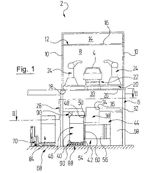
In Figure 1, 2 denotes a paint booth, as a whole, of a
surface treatment plant in which vehicle bodies 4 are
painted after they have been cleaned and degreased, for
example, in the pre-treatment stations which are located
upstream in the paint booth 2 and are not shown
specifically. The paint booth 2 rests on a steel
construction 6 as is known per se.
The paint booth 2 comprises a paint tunnel 8, which is
arranged at the top and is delimited by vertical side
walls 10 and a horizontal booth ceiling 12, but is open
at the end faces. Moreover, the paint tunnel 8 is open to
the bottom in such a way that overspray-laden booth air
can flow downwards. The booth ceiling 12 is constructed
CA 02840111 2013-12-20
,
WO 2013/013780 - 10 -
PCT/EP2012/002948
in conventional manner as a lower delimitation of an air
supply chamber 14 with a filter cover 16.
Arranged above a lower opening 18 of the paint tunnel 8,
there is a steel framework 20 which supports conveying
technology 22 which is known per se and is not discussed
in more detail here. This can be used to transport
vehicle bodies 4 to be painted from the entry side of the
paint tunnel 8 to its exit side. Located inside the paint
tunnel 8 are application devices in the form of multi-
axle application robots 24, which are known per se. The
vehicle bodies 4 can be coated with paint by means of the
application robots 24.
The lower opening 18 of the paint tunnel 8 is covered by
an accessible grating 26. Located beneath the grating 26,
there is a plant region 28 in which the overspray
particles entrained by the booth air are separated from
the booth air.
Therefore, air flows out of the air supply chamber 14
downwards through the paint tunnel 8 to the plant region
28, whereby paint overspray which is present in the paint
tunnel 8 is taken up and entrained by the air.
The plant region 28 comprises a flow region 30 into which
the overspray-laden booth air flows first and which, to
this end, is open at the top towards the paint booth 2,
but delimited at the side by the side walls 10 and at the
CA 02840111 2013-12-20
WO 2013/013780 - 11 -
PCT/EP2012/002948
bottom by an intermediate ceiling 32. The intermediate
ceiling 32 has a plurality of passages 34 arranged in
succession in the longitudinal direction of the booth.
Each of these passages 34 leads to a channel inlet 36 of
a respective air guide channel 38 into which the booth
air which is laden with overspray particles firstly flows
by and large vertically downwards.
The air guide channel 38 then deflects the booth air
through 900 into the horizontal, whereupon it then flows
into a filter module 40 in a by and large horizontal
direction. Each filter module 40 forms a separating unit
which operates with a separating device denoted as a
whole by 42, which is present in a separating region 44
of the paint booth 2 which is arranged below the flow
region 30.
Each filter module 40 is detachably connected to one of
the air guide channels 38. To this end, each filter
module 40 has a filter housing 46 with a filter inlet 48
which is constructed complementarily to a channel outlet
connection 50 of the air guide channel 38 so that the
filter module 40 can be fluidically connected to, or
disconnected from, the channel outlet connection 50 of
the air guide channel 38 by a corresponding horizontal
movement.
CA 02840111 2013-12-20
WO 2013/013780 - 12 -
PCT/EP2012/002948
The separating device 42 in the present exemplary
embodiment is therefore a separating filter which is
assembled in modular fashion from the filter modules 40.
The booth air is deflected twice more through 90 in the
filter module 40, then flows through a filter unit in the
form of an inertial filter 52 on which the paint
overspray separates, and exits the filter module 40
through a filter outlet connection 54 on the same side of
the filter housing 46 as that on which the filter inlet
48 is located. From there, the booth air, which is now
substantially free of overspray particles, flows into an
intermediate channel 56 by way of which it arrives in a
collecting flow channel 58.
The intermediate channel 56 has an inlet flange 60, it
being possible for the filter outlet connection 54 of the
filter module 40 to be fluidically connected to, or
disconnected from, this inlet flange 60 through its
horizontal movement described above. A filter module 40
is therefore ready for use in an operating position when
its filter inlet 48 is connected to the channel outlet
connection 50 of the air guide channel 38 and its filter
outlet connection 54 is connected to the inlet flange 60
of the intermediate channel 56.
The booth air is supplied for further treatment and
conditioning by way of the collecting flow channel 58 and
is subsequently conducted in a circuit (not shown
CA 02840111 2013-12-20
WO 2013/013780 - 13 -
PCT/EP2012/002948
specifically here) back into the air supply chamber 14
from which it flows back into the paint tunnel 8 from
above. In the event that the booth air has not yet been
adequately freed of overspray particles by the separating
filter 42, further filter stages can be provided
downstream of the separating filter 42, to which the
booth air is supplied and in which fleece filters or
electrostatically operating separating filters are used,
as are known per se. It is also optionally possible to
integrate one or more of such filter stages in the filter
module 40. A filter fleece can therefore be arranged for
example upstream of the filter outlet connection 54.
One of the filter modules 40 is now explained in more
detail with reference to Figure 3. As can be seen
therein, the filter housing 46 of the filter module 40
delimits a flow chamber 62 which extends between the
filter inlet 48 and the filter outlet connection 54 and
through which the booth air flows on a flow path which is
curved through 180 .
The filter housing 46 in turn comprises a base part 64
and a chamber cover 66 which is supported by the base
part 64 and in which a chamber wall has the filter inlet
48 and the filter outlet connection 54. In terms of its
geometry and its dimensions, the base part 64 is
constructed as a standardised supporting structure and
for example in accordance with a with a so-called Euro
pallet. It is thus possible for a filter module 40 to be
CA 02840111 2013-12-20
WO 2013/013780 - 14 -
PCT/EP2012/002948
moved by a conveyor system 68 adapted to such standard
structures and to be brought into, or removed from, its
operating position. This is indicated in Figure 1 using
the example of an elevating conveyor truck 70 which can
be operated manually by an operator.
The arrangement of the filter modules 40 in the
separating region 44 of the paint booth 2 can take place
accordingly in grid formation, which rests on the
standardised base part 64 used.
At least a lower collecting region of the filter module
40 is liquid-tight and therefore designed as a collecting
trough 72 for paint which is separated at the inertial
filter 52 and flows downwards therein.
The inertial filter 52 is arranged upstream of the filter
outlet connection 54 in the flow chamber 62 in such a way
that the overspray-laden booth air flows through it in a
horizontal direction 74. The inertial filter 52 comprises
a supporting structure 76 with a substantially horizontal
supporting plate 78 - as shown in Figure 3, the
supporting plate 78 here is angled slightly downwards
with respect to the horizontal in the flow direction of
the booth air entering the filter module 40 - which is
mounted inside on the housing wall of the filter housing
46 with the filter inlet 48 and the filter outlet
connection 54.
CA 02840111 2013-12-20
WO 2013/013780 - 15 -
PCT/EP2012/002948
The supporting plate 78 supports a plurality of filter
plates 80 which serve as separating elements and extend
downwards in the direction of the collecting trough 72
and of which only a few are provided with a reference
numeral for the sake of clarity. As in the present
exemplary embodiment, this can be implemented for example
in such a way that the supporting plate 78 has slots 82
which are complementary to the filter plates 80 and in
which the filter plates 80 are inserted. Of the slots 82,
again only a few have a reference numeral.
The filter plates 80 are V-shaped in cross-section and
arranged such that the point of the V faces in the flow
direction 74 of the air, in which the booth air flows
through the inertial filter 52. The filter plates 80 here
are arranged offset from one another, with the number of
filter plates 80 increasing in the flow direction 74 of
the booth air. In other words, the spacing between the
filter plates 80 decreases in the flow direction 74 and
in a direction perpendicular thereto, i.e. in the
horizontal direction here. This principle is shown in
Figure 2 for a replacement filter module 84 which is
shown in vertical section and which will replace a fully-
laden filter module 40.
In this way, a flow labyrinth, through which the booth
air flows and in which the overspray particles are
separated at the filter plates 80 in a manner known per
se in accordance with the principle of mass inertia, is
CA 02840111 2013-12-20
WO 2013/013780 - 16 -
PCT/EP2012/002948
formed in the flow direction 74 in the inertial filter
52. From there, the overspray flows downwards into the
collecting trough 72 where the overspray accumulates into
a paint sump.
Instead of the filter plates 80, it is also possible to
use separating elements which have a different
construction in terms of their geometry and dimensions.
Figure 4 shows a modified filter module 40 in which
filter cartridges 86 are supported by the supporting
plate 78 of the supporting structure 76, instead of the
filter plates 80. The filter cartridges 86 here are
arranged according to the same principle as the filter
plates 80 in the filter module 40 according to Figure 3.
In practice, it is also possible to provide other
arrangements of the separating elements.
Instead of the filter plates 80 or filter cartridges 86,
it is also possible to provide compartment structures or
chamber structures as separating elements. Plates or
sheets which are connected to one another in foldable or
plug-in manner can serve for example as compartment
structures. In practice, chamber structures have a
honeycomb-like design.
As can be seen in Figure 1, the filter module 40 rests on
scales 88 in its operating position and is locked in its
operating position at the top and bottom by means of a
locking device 90.
CA 02840111 2013-12-20
WO 2013/013780 - 17 -
PCT/EP2012/002948
Each filter module 40 is designed to hold a maximum
quantity of paint, i.e. for an overspray loading limit
which depends on the type of filter module 40 and the
materials used for this. The quantity of paint which has
already been collected can be monitored by the scales 88.
Alternatively, the loading limit can be established by
determining the differential pressure. The air resistance
built up by the filter module 40 increases as the filter
module 40 becomes more loaded.
When a filter module 40 has reached its maximum holding
capacity, the locking device 90 is released, the fully-
laden filter module 40 is moved out of the separating
region 44 of the paint booth 2 by means of the elevating
conveyor 70 and replaced with an empty filter module 40.
To this end, the flow connection between the filter
module 40 to be replaced and the guide channel 38 and the
connecting channel 46 is interrupted in advance in that
the channel outlet connection 50 of the guide channel 38
and the inlet flange 60 of the connecting channel 56 are
closed by means of a stop valve (not shown specifically).
When the empty filter module 40 is moved into its
operating position on the scales 88, it is locked
accordingly by the locking device 90 and therefore
secured against being inadvertently moved out of the
separating region 44. The stop valves of the guide
channel 38 and the connecting channel 56 are brought back
CA 02840111 2013-12-20
. WO 2013/013780 - 18 -
PCT/EP2012/002948
into an open position so that the booth air flows through
the newly positioned filter module 40.
The replaced overspray-laden filter module 40 is then
supplied to a disposal and/or recycling process and
therefore used as a disposable filter module.
In other words, the filter modules 40 in which overspray
is separated are therefore constructed as replaceable
disposable units with a filter housing 46 and a filter
unit 52, with each filter module 40 being replaced with
an empty filter module 40 after reaching an overspray
loading limit.
Figure 5 shows a further modified conveyor system 68 as a
variation. Instead of an elevating conveyor truck, this
shows a roller conveyor system 92, which comprises roller
conveyors with motor-driven rollers in a manner known per
se. By means of the roller conveyor system 92, filter
modules 40 whereof the holding capacity for paint
overspray is exhausted can be moved out of the separating
region 44 of the paint booth 2 under computer control and
replaced with a respective unloaded filter module 40. To
this end, the roller conveyor system 92 comprises
cooperating conveyor units by means of which filter
modules 40 can be moved parallel and/or transversely to
the longitudinal extent of the paint booth 2.
CA 02840111 2013-12-20
'
WO 2013/013780 - 19 -
PCT/EP2012/002948
The base part 64, the chamber housing 66, the supporting
structure 76 and the separating elements 80, 86 of the
filter module 40 are made from a wet-strength recycling
material. Generally speaking, one component, several
components or all the components of the filter module 40
are made from a wet-strength recycling material.
Cellulose materials, such as optionally treated paper and
paperboard materials, corrugated cardboard, cardboards
with vertical corrugations, cardboards with a honeycomb
structure or cardboard wrap as well as other materials,
such as MDF materials, can be used for this. A wooden
Euro pallet is suitable for example as the base part 64.
Plastics, particularly such as polyethylene or
polypropylene, are also possible.
The filter module 40 here can itself be delivered as a
modular kit comprising the said components in individual
parts and assembled on site. The chamber housing 66 here
can have for example a collapsible ceiling and be folded
along two diagonally opposed longitudinal edges into a
two-layer housing plate. The unfolded chamber housing 66
is then slipped for example over the inertial filter 52,
which has been assembled in advance from the supporting
structure 76 and the filter plates 80 or filter
cartridges 86.
After the inertial filter 52 has then been mounted on the
chamber housing 66, this structural unit is placed on the
base part 64 and possibly secured thereto by adhesion.
CA 02840111 2013-12-20
WO 2013/013780 - 20 -
PCT/EP2012/002948
To construct the collecting trough 72, a sealing mass can
be injected into the base region and distributed
uniformly in the base region of the flow chamber 62 using
a nutating table.
Figures 6 and 7 show an alternative collecting trough 94
to this. Here, the base part 64 supports a rotating
trough frame 96, which can likewise be made from one of
the above-mentioned wet-strength recycling materials, for
example from thin wooden blocks. A liquid-tight
collecting bag 98, in which the chamber housing 66 can be
placed and whereof the upper edge is folded outwards over
the trough frame 96, is inserted into the trough frame
96. It has been shown in practice that so-called Big-Bags
can be used as a collecting bag 98, which are known per
se as packaging for example for powder paint.
The modular construction of the separating device 42
enables it to be of a compact design such that it can be
arranged as an entire device within the inner contour of
the paint booth 2, which is created by the steel
structure 6 in the present exemplary embodiments. This is
clearly shown in Figure 1. In this way, the surface area
required for the paint booth 2 is also not increased by
the separating device 42. This enables ready-assembled
paint booths to be retrofitted with the separating device
42. This compactness of the separating device 42 as a
whole is here based on the compactness of the individual
filter modules 40.