Note: Descriptions are shown in the official language in which they were submitted.
CA 02840238 2013-12-20
WO 2013/012849 PCT/US2012/047039
CONTROL VALVE MONITORING SYSTEM
FIELD OF THE DISCLOSURE
[0001] The present disclosure relates generally to maintenance of control
valves and, more
specifically, to a system for detecting shaft and stem fatigue in a control
valve.
BACKGROUND OF THE DISCLOSURE
[0002] A control valve regulates the rate of fluid flow as the position of a
valve plug or
disk is changed by force from an actuator. To do this, the control valve must:
(1) contain the
fluid without external leakage; (2) have adequate capacity for the intended
service; (3) be
capable of withstanding the erosive, corrosive, and temperature influences of
the process; and
(4) incorporate appropriate end connections to mate with adjacent pipelines
and actuator
attachment means to permit transmission of actuator thrust to the valve plug
stem or rotary
shaft, for example.
[0003] Many styles of control valves are known. For example, sliding-stem
control valves
and rotary-shaft control valves are well known in the field of process control
valves. Sliding-
stem control valves include globe valves, which are valves having a linear
motion closure
member, one or more ports, and a body distinguished by a globular shaped
cavity around a
port region. Sliding-stem control valves typically employ a plug for their
closure member
that is positioned in the flow path to modify the rate of flow through the
valve. The sliding-
stem control valve further includes a valve stem having a first end connected
to the closure
member and a second end opposite the first end that is connected to an
actuator.
[0004] A rotary-shaft control valve is a valve in which the flow control
member, such as a
full ball, partial ball, sphere or disk, is rotated in the flowstream to
control the capacity of the
valve. The rotary-shaft control valve includes a shaft that corresponds to the
valve stem of a
globe or sliding-stem valve.
[0005] Some methods of detecting fatigue and an onset of cracking in a shaft
of a rotary-
shaft control valve or a stem of a sliding-stem control valve are known. For
example, it is
known to mount strain gauges on control valve stems and shafts to verify that
a force or
torque has been transmitted to the valve once a positioner and an actuator
have been given a
control signal to close.
[0006] It is desired, however, to detect cracks in the valve stem or shaft
that are too small
to be identified by visual inspection, for example. It is also desired to
detect cracks and
1
CA 02840238 2013-12-20
WO 2013/012849 PCT/US2012/047039
fatigue in the valve stem and shaft earlier and more accurately than current
methods allow.
By doing so, end users are alerted that the control valve is in need of
replacement parts and
service, promoting more efficient maintenance and a longer useful life of the
control valve.
SUMMARY OF THE DISCLOSURE
[0007] A control valve monitoring system comprises at least one sensor
connected to one
of a valve stem or valve shaft and a device for providing data regarding the
change in
mechanical integrity of one of the valve stem or valve shaft. The at least one
sensor of the
control valve monitoring system may be one of an acoustic emission sensor or
an active
ultrasonic sensor. The acoustic emission sensor may detect cracking in one of
the valve shaft
or valve stem through a change in acoustic signature, and the acoustic
emission sensor may
be attached to an end of the valve shaft or valve stem. The at least one
sensor may also be
one of a piezoelectric wave active sensor or a piezoceramic (PZT) sensor, such
that the
impedance of one of the piezoelectric wave active sensor and the PZT sensor to
the valve
shaft or stem may be correlated to the impedance of the valve shaft or valve
stem, allowing a
change in mechanical integrity of the valve shaft or valve stem to be
detected.
[0008] Further, the piezoelectric wave active sensor or the PZT sensor may be
attached to
an outer diameter of a valve shaft or valve stem between a valve control and
an actuator. In
addition, the at least one sensor may be an optical fiber Bragg grating (FBG)
sensor. The
FBG sensor may measure strain at a localized area of the valve shaft or valve
stem. Further,
the FBG sensor may be attached to an outer diameter of the valve shaft or
valve stem
between a valve control and an actuator. Still further, the at least one
sensor may be wireless.
The at least one sensor may be incorporated into the valve stem or valve shaft
during
manufacture of the valve stem or valve shaft. The at least one sensor may be
attached to the
valve shaft or valve stem by one or more of a bonding agent, a soldering
agent, or a bolt. The
control valve monitoring system may further include a memory and a power
source for data
gathering and reporting of faults in the valve shaft or valve stem.
[0009] In another example of the disclosure, a method of detecting a change in
mechanical
integrity of a valve shaft of a rotary-shaft control valve or a valve stem of
a sliding-stem
control valve comprises integrating at least one sensor into a valve shaft or
a valve stem and
sensing fatigue in the valve shaft or valve stem using structural health
monitoring technology.
BRIEF DESCRIPTION OF THE SEVERAL VIEWS OF THE DRAWINGS
[0010] FIG. 1 is a cross-sectional view of a rotary-shaft control valve;
2
CA 02840238 2013-12-20
WO 2013/012849 PCT/US2012/047039
[0011] FIG. 2 is a cross-sectional view of a sliding-stem control valve;
[0012] FIG. 3 is a perspective view of a shaft of the rotary-shaft control
valve of FIG. 1
having a control valve monitoring system incorporated therein; and
[0013] FIG. 4 is a perspective view of a shaft of the rotary-shaft control
valve of FIG. 1
having another embodiment of a control valve monitoring system incorporated
therein.
DETAILED DESCRIPTION OF THE DISCLOSURE
[0014] Referring now to FIG. 1, a rotary-shaft control valve 10 is
illustrated. The rotary-
shaft control valve 10 includes a valve body 12, a valve inlet 14, a valve
outlet 16, and a flow
passage 18 that extends between the valve inlet 14 and the valve outlet 16.
The flow passage
18 includes a control passage 20, and a moveable control element 22 is
moveably disposed in
the control passage 20. The control element 22 is a rotary control element 22A
that is
connected to a valve shaft 24. The control element 22A may be, for example, a
valve disk, a
partial or full ball, or any other form of rotating control element. The valve
shaft 24 is
operatively coupled to an actuator (not shown), which may be any kind of
actuator commonly
employed in the art.
[0015] The control element 22 is positioned such that the control element 22
is disposed
within the control passage 20, and the position of the control element 22
within the passage
20 can be controlled using the actuator (not shown), controlling the amount of
fluid flow
through the control passage 20. The control valve 10 includes a bore 27 that
is sized to
receive the valve shaft 24. The valve body 12 includes a packing box 28, and a
primary
packing set 30 is disposed in the packing box 28. The packing set is sized to
fit around the
valve shaft 24.
[0016] Referring now to FIG. 2, a sliding-stem control valve 100 is
illustrated. Like the
rotary-shaft control valve 10, the sliding-stem control valve 100 also
includes a valve body
112, a valve inlet 114, a valve outlet 116, and a flow passage 118 extending
between the
valve inlet 114 and the valve outlet 116. The flow passage 118 also includes a
control
passage 120, and a moveable control element 122 disposed in the control
passage 120. The
control element 122 is a linear control element 122A, such as a plug, that is
connected to a
first end of a valve stem 124. A second end of the valve stem 124 disposed
opposite the first
end is operatively connected to an actuator (not shown) commonly employed in
the art.
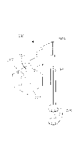
[0017] Referring now to FIG. 3, the shaft 24 of the rotary-shaft control valve
10 of FIG. 1
is illustrated. The shaft 24 includes a portion of the rotary control element
22A at one end. A
3
CA 02840238 2013-12-20
WO 2013/012849 PCT/US2012/047039
control valve monitoring system 200 is integrated into the shaft 24. In a
similar manner, the
control valve monitoring system 200 may also be integrated into the stem 124
of the sliding-
stem control valve 100 of FIG. 2. The control valve monitoring system 200
includes a sensor
210 for detecting an onset of cracking or change in material property of the
shaft 24 or stem
124. More specifically, an acoustic emission sensor 210A is attached to one
end of the valve
shaft 24 or stem 124 via a bolt or other attachment mechanism. The acoustic
emission sensor
210A detects a change in the mechanical integrity of the valve shaft 24 or
stem 124 (FIG. 2)
through a change in acoustic signature using structural health monitoring
(SHM) technology.
[0018] Generally, SHM is the process of implementing a damage detection and
characterization strategy for engineering structures. Damage is often defined
as changes to
the material and/or geometric properties of a structural system, which
adversely affect the
system's performance. The SHM process involves observing a system over time
using
periodically sampled dynamic response measurements from an array of sensors,
the
extraction of damage-sensitive features from these measurements, and the
statistical analysis
of these features to determine the current state of the system health. See,
e.g.,
http://en.wikipedia.org/wiki/Structural_health_monitoring, April 13, 2011.
[0019] The control valve monitoring system 200 further includes a device 220
for
providing data regarding the change in mechanical integrity of one of the
valve stem 124 or
valve shaft 24. The device 220 may be a local digital valve positioner, a
stand alone device
for data collection/reduction, an asset management software package, or a
control system,
such as a Delta V control system.
[0020] Referring back now to FIG. 3, the sensor 210A detects a change in the
mechanical
integrity of the valve shaft 24 or stem 124 (FIG. 2) through a change in
acoustic signature
between the sensor 210A and the valve shaft 24 or stem 124. Data regarding the
change in
the mechanical integrity of the valve shaft 24 or stem 124 (FIG. 2) is then
provided to an end
user. More specifically, a detected fault or deviation from a baseline
signature may be
communicated to a local digital valve positioner, a stand alone device for
data
collection/reduction, an asset management software package, or a control
system, such as
Delta V, each of which may be a part of the control valve monitoring system
200. In one
example, the detected fault triggers an alert in the digital valve positioner
or data collection
system (not shown), which would provide an indication of change in state or
impending
failure of the valve shaft 24 or stem 124. If the sensor 210A indicates shaft
24 or stem 124
(FIG. 2) crack detection, the end user is allowed time to prepare for
maintenance of the valve
4
CA 02840238 2013-12-20
WO 2013/012849 PCT/US2012/047039
shaft 24 or stem 124. In another example, the system 200 may also determine a
rate of
change of the detected damage and could, therefore, provide an estimate of
remaining useful
life of the component.
[0021] Referring now to FIG. 4, the shaft 24 of the rotary-shaft control
valve 10 of FIG. 1
is again illustrated with another control valve monitoring system 300 using
SHM technology.
In a similar manner, the control valve monitoring system 300 may also be used
with the stem
124 of the sliding-stem control valve 100 of FIG. 2. The control valve
monitoring system
300 includes at least one sensor 310A that may be an optical fiber Bragg
grating (FBG)
sensor 310A for detecting a crack or change in material property of the shaft
24 or stem 124.
The FBG sensor 310A is attached via bonding or soldering to an outer diameter
of the shaft
24 or stem 124 between the valve element 22A and the actuator (not shown)
disposed on an
end of the shaft 24 opposite the valve element 22A. The FBG sensor 310A
measures strain at
a localized area on the shaft 24 or stem 124 (FIG. 2). By doing so, the
control valve
monitoring system 300 incorporates physical characteristic measurements of the
valve shaft
24 or stem 124 (instead of an inferred or calculated estimation of component
fatigue),
providing time for an end user to prepare for maintenance of the valve shaft
24 or stem 124.
[0022] The sensor 310A of the control valve monitoring system 300 may
alternatively be
an active ultrasonic sensor that detects a change in the mechanical integrity
of the valve shaft
24 or stem 124 (FIG. 2) through the change in ultrasonic Lamb waves between
the ultrasonic
sensor and the valve shaft 24 or stem 124. More specifically, the active
ultrasonic sensor and
actuator give the valve shaft 24 or stem 124 (FIG. 2) material a little pinch
and then wait to
record the resultant ultrasonic waves that propagate through the component.
Cracks or other
defects in the valve shaft 24 or stem 124 material will distort the reflected
waves. These
active ultrasonic sensors may be attached via bonding or soldering to an outer
diameter of the
shaft 24 or stem 124 or the end of the shaft 24 or stem 124, as illustrated
for example in FIG.
3. However, the active ultrasonic sensors tend to be mounted on the end of the
valve shaft 24
for rotary valves and the outer diameter of the valve stem 124 (FIG. 2) for
sliding stem valves
(FIG. 2).
[0023] In yet another embodiment, the sensor 310A of the control valve
monitoring system
300 may be one or more of a piezoelectric wave active sensor or a piezoceramic
(PZT)
sensor. In this case, the impedance of the piezoelectric wave active sensor or
the PZT sensor
(FIG. 2) is correlated to the impedance of the shaft 24 or stem 124, allowing
a change in
mechanical integrity of the valve shaft 24 or stem 124 to be detected.
CA 02840238 2013-12-20
WO 2013/012849 PCT/US2012/047039
[0024] Like the control valve monitoring system 200 of FIG. 3, the control
valve
monitoring system 300 further includes a device 320 for providing data
regarding the change
in mechanical integrity of one of the valve stem 124 or valve shaft 24. The
device 220 may
be a local digital valve positioner, a stand alone device for data
collection/reduction, an asset
management software package, or a control system, such as a Delta V control
system.
[0025] While the sensors 210A and 310A may be attached to the valve shaft 24
and stem
124 using a bonding agent, a soldering agent, bolts or other attachment
mechanisms known to
those of skill in the art, the sensors 210A and 310A may alternatively be
incorporated into the
valve shaft 24 or stem 124 during manufacture of the same.
[0026] Still further, for acoustic or ultrasonic measurements, the sensors
210A and 310A
may be connected to the local digital valve positioner or stand alone device
for data
collection/reduction using a single cable or wireless signal (not shown). For
the Fiber Bragg
Grating (FBG) design, the sensors 210A and 310A may be connected to the
digital valve
positioner or stand alone device using optical fiber. When using multiple FBG
sensors on
one control valve assembly, many FBG sensors may be connected in series using
a single
optical fiber. For acoustic or ultrasonic measurements, each sensor 210A, 310A
may be on
its own cable or wireless address. Using wireless sensors with the control
valve monitoring
systems 200, 300 helps ease installation costs of the sensors 210A and 310A
and eliminates
fatigue of cable assemblies associated with the sensors 210A and 310A
physically attached to
the valve shaft 24 and stem 124 by various attachment mechanisms noted above.
[0027] In addition, the control valve monitoring systems 200, 300 may also
include power
and memory devices that allow for constant data gathering and reporting of
faults.
[0028] Numerous modifications and alternative embodiments of the disclosure
will be
apparent to those skilled in the art in view of the foregoing description.
Accordingly, this
description is to be construed as illustrative only and is for the purpose of
teaching those
skilled in the art the best mode of carrying out the invention. The details of
the present
disclosure may be varied without departing from the spirit of the invention,
and the exclusive
use of all modifications that are within the scope of the claims is reserved.
[0029] Thus, while particular embodiments and applications have been
illustrated and
described, it is to be understood that the disclosed embodiments are not
limited to the precise
construction and components described herein. For example, those skilled in
the art will
appreciate that the outer diameter of the shaft 24 or stem 124 to which at
least one sensor
6
CA 02840238 2013-12-20
WO 2013/012849 PCT/US2012/047039
210A (Fig. 3), 310A (Fig. 4) is attached is equivalent to an outer surface of
the shaft 24 or
stem 124. In addition, while the two control valve monitoring systems 200, 300
described
herein are illustrated in Figs. 3 and 4 as being integrated into the shaft 24
of the rotary-shaft
control valve 10 of Fig. 1, the two control valve monitoring systems 200, 300
can also be
fully integrated into the stem 124 of the sliding-stem control valve 100 of
Fig. 2. Still further,
those skilled in the art will also appreciate that the devices 220, 320 for
providing data
regarding the change in mechanical integrity of one of the valve stem 124 or
valve shaft 24
may include one or more of a processor, a memory, a battery, and a wireless
interface and
still fall within the spirit and scope of the appended claims. In one example,
the device 220
of Fig. 3 includes a processor 222, a memory 224, a battery 226, and a
wireless interface 228,
and the device 320 of Fig. 4 may also include one or more of the same. In sum,
and as
explained herein, these various modifications and others may be made in the
arrangement,
operation and details of the system and method disclosed herein without
departing from the
scope defined in the appended claims.
7