Note: Descriptions are shown in the official language in which they were submitted.
CA 02840622 2013-12-24
WO 2013/004893 PCT/F12012/050613
1
ARRANGEMENT AND METHOD FOR ICING DETECTION
FIELD OF THE INVENTION
Generally the present invention pertains to measuring and optics. In
particular,
the invention is related to icing detection based on optical remote sensing.
BACKGROUND
Contemporary solutions for assessing the icing conditions of various surfaces
and
related elements differ considerably depending on the implementation and
related
use scenario.
Atmospheric icing takes place when water droplets in the atmosphere freeze on
a
contacted object. For example, in connection with aircrafts the ice may
increase
the risk of stalling of the airfoil. Thereby, the ice built-up should be
detected as
early and reliably as possible. For instance, an electromechanical probe with
an
oscillating (vibrating) sensing element may be provided on the nose of the air-
craft, whereupon the ice accreted thereon causes changes in the oscillation
fre-
quency depending on the thickness of the ice layer. The oscillation frequency
is
monitored for estimating the amount of ice.
As another use scenario, the wind turbines of wind farms may be heavily
affected
by ice on the rotor blades. The blades may crack and the production efficiency
may drastically decrease. The overall wear of the turbine may also increase
due
to mass and aerodynamic imbalances and additional friction all caused by the
ice.
Introduction of the aforesaid oscillating probe into the nacelle of a wind
turbine
has been suggested, so has been the use of various capacitance-, impedance-,
and
inductance-based detectors requiring the addition of specific sensors on the
rotor
blades. Further, different optical sensors monitoring the ice accumulated on a
sensor surface based on e.g. changes on light reflection from the surface have
been set forth.
However, e.g. the oscillation probe may not suit all use scenarios and may
turn
out too slow as to the achieved detection response. It is relatively complex
by na-
ture and requires integration with the turbine nacelle. The capaci-
tance/impedance/inductance-based sensors may, on the other hand, work unrelia-
CA 02840622 2013-12-24
WO 2013/004893 PCT/F12012/050613
2
bly after the first detection as the ice removal from the sensor by heating,
for ex-
ample, may easily at least partially fail, whereupon the subsequent detections
may be inaccurate. Similar flaws have been recognized with many optical sens-
ing solutions.
In summary, many known arrangements to detect icing still suffer from reliabil-
ity problems at least in certain type of operational conditions. Yet, their
detection
areas are limited as they represent only a single or few points in space, i.e.
the
sensor surface locations. In any case, the arrangements are merely capable of
de-
tecting already-formed ice, which may be too late depending on the
application.
To broadly just estimate the icing potential in the atmosphere a number of
solu-
tions have been disclosed most of which utilizing a plurality of more or less
di-
rectly measurable prognostic weather parameters such as temperature and humid-
ity combined via a deduction logic to predict icing. Even these solutions
typically
bear many weaknesses comparable to the ones already contemplated above.
SUMMARY OF THE INVENTION
The objective is to alleviate one or more problems described hereinabove not
yet
addressed by the known icing detection arrangements, and to provide a feasible
solution for detecting atmospheric icing such as in-cloud icing.
The objective is achieved by the embodiments of an arrangement and a method
in accordance with the present invention.
Accordingly, in one aspect of the present invention an arrangement, e.g. one
or
more devices, for the detection of atmospheric icing conditions comprises
-a lidar (light detection and ranging) entity, such as a Doppler lidar entity,
con-
figured to emit electromagnetic radiation, optionally in a number of
directions, to
the atmosphere and to receive radiation backscattered from the aerosol, such
as a
cloud, present in the atmosphere, and
-a data processing entity configured to obtain at least one indication of
signal in-
tensity, such as the CNR (carrier-to-noise ratio) or other indicative
parameter, on
the basis of the received backscattered signal relative to a number of
distances
such as heights from a predetermined basic level such as the location of the
lidar,
CA 02840622 2013-12-24
WO 2013/004893 PCT/F12012/050613
3
further configured to compare the at least one indication of signal intensity
with
at least one predetermined reference in order to obtain an indication of the
likeli-
hood of cloud presence at said number of distances, and
configured to determine an indication of the icing potential at said number of
dis-
tances on the basis of the comparison and an indication of the temperature at
said
number of distances.
In one embodiment, the lidar includes a Doppler heterodyne (coherent) lidar.
The
lidar may be a pulsed lidar or a continuous wave lidar. The lidar may utilize
wavelengths in the ultraviolet, visible, or near infrared range.
Alternatively, an
incoherent lidar may be utilized. The lidar may be additionally configured to
measure wind speed.
In another embodiment, the data processing entity is configured to obtain a
posi-
tive indication of the potential presence of a cloud at a distance when the
indica-
tion of signal intensity, such as a numerical value, substantially corresponds
to
the reference. Alternatively, a positive indication may be obtained when the
indi-
cation of signal intensity substantially differs from the reference. In the
case of a
numerical representation, a substantially larger or smaller value, or a
plurality of
values in the case of multiple indications or a multi-value indication, may
imply
such substantial difference mapped to a positive indication of the likelihood
of
cloud presence. The indication of the likelihood of cloud presence may be of
Boolean (0/1) type or more comprehensive indication (e.g. probability) as con-
templated in further detail hereinbelow.
In a further embodiment, the arrangement is configured to characterize the
icing
potential at the number of distances. The characterization may include an
indica-
tion of a parameter such as the average droplet size and/or liquid water
content,
for instance.
Still in a further embodiment, the arrangement is configured to determine an
in-
dication of precipitation conditions at the number of distances. The
indication
may be applied in determining the icing potential and/or icing
characteristics.
In a further embodiment, the arrangement may be configured to trigger and/or
it
comprises a countermeasure activation entity configured to trigger anti-icing
or
CA 02840622 2013-12-24
WO 2013/004893 PCT/F12012/050613
4
de-icing procedure such as a heating or microwave excitation procedure to pre-
vent, reduce or slow down ice accretion on a predetermined surface. The con-
trolled heating or excitation means may be integrated with the arrangement or
provided as separate therefrom. Heating may be implemented through blowing
hot air or other gas, funneling heated wires or other elements or e.g. heated
liquid
(by liquid circulation system, for instance) to the target area(s), etc. For
anti-icing
use the target area(s) may include ice-repellant coating such as silicon
paint, for
example. Alternatively or additionally, the arrangement may be configured to
trigger altering the state of a functionally connected target device such as a
wind
turbine. The state change may include stopping the turbine or generally,
altering
the rotation characteristics such as the speed of the rotor, for example.
In a further embodiment, the arrangement is configured, in order to determine
the
indication of the icing potential, to verify whether the temperature measured
and/or estimated fulfills a predetermined condition. For example, in case the
temperature is (optionally equal or) below a predetermined threshold or within
a
predetermined range, e.g. few degrees such as one, two, three or four degrees,
relative to a predetermined reference point such as the zero degrees Celsius,
i.e.
the normal freezing point of water, the arrangement is configured to consider
the
temperature condition for icing as fulfilled. The range around the reference
point
may be symmetrically or asymmetrically disposed. The indication of the temper-
ature may thus be of simple Boolean (1/0, True/False) type.
In a further embodiment, the arrangement may be configured to consider the ic-
ing as likely when the likelihood of cloud presence is high, e.g. over a
predeter-
mined threshold, and the temperature condition for icing is fulfilled as
implied by
the corresponding indications.
Alternatively, the indication of the temperature used in the determination of
the
icing potential may be of higher resolution and optionally indicate the
measured
temperature(s) in full integer or one decimal place centigrade values, for
exam-
ple.
In a further embodiment, the arrangement configured to determine the
indication
of the signal intensity such as CNR is further configured to compare it with
at
least one predetermined reference (CNR). The reference may be indicative of
substantially clear condition with no clouds. In that case the reference such
as the
CNR may be low or generally contain small values according to predetermined
CA 02840622 2013-12-24
WO 2013/004893 PCT/F12012/050613
criterion, for instance, due to the lower amount of backscattered radiation.
If the
measured indication then substantially differs from the reference, i.e. the
meas-
ured indication is generally higher according to predetermined criterion or
crite-
ria (e.g. predetermined amount of dB), for instance, the likelihood of cloud
pres-
5 ence may be deemed high. To the contrary, if the reference indicates
cloudy
condition, the associated value may be relatively high. As a further
alternative
depending on the embodiment, the reference may be set to indicate a predeter-
mined threshold scenario somewhere between substantially clear and extremely
cloudy conditions, for example.
The likelihood may be indicated via simple 1/0, Yes/No, True/False, or other
coarse, substantially Boolean or binary type condition variable, or a more com-
prehensive numerical range with at least one value between the extremes may be
utilized, for example. In such a range, one end may indicate the lowest
probabil-
ity of cloud presence, whereas the opposite end the highest probability.
In a further embodiment, the used reference may be dynamic and/or adaptive. It
may be optionally automatically adapted based on at least one factor selected
from the group consisting of: time of day, season, month, week, year, time,
loca-
tion, altitude, latitude, longitude, and temperature. Accordingly, the logic
for de-
termining the indication of the likelihood of cloud presence and icing
potential
may be dynamic and/or adaptive.
In some embodiments the actions of comparison and icing potential indication
determination may be combined and executed e.g. in parallel. For example, they
may result from calculating the same formula(e) utilizing the determined
indica-
tion of signal intensity and the indication of the temperature as input. In
certain
embodiments, even the indication determination may be combined therewith. Al-
ternatively, the determination and the comparison actions may be combined.
In a further embodiment, a wind turbine, a windmill or a wind farm comprises
at
least one aforementioned arrangement of the present invention as separate (sys-
tem of wind turbine(s) and at least one arrangement) or at least partially
integrat-
ed therewith. The arrangement may be installed at the turbine hub, rotor,
nacelle,
tower, base, or it may be disposed on the ground near-by, for instance. Each
wind
turbine may have a dedicated arrangement, or it may be shared among multiple
turbines.
CA 02840622 2013-12-24
WO 2013/004893 PCT/F12012/050613
6
In a further embodiment, the wind turbine, windmill or wind farm may comprise
anti-icing and/or de-icing means such as a heating means to prevent the rotor
blades and/or other element(s) from icing.
In another aspect of the present invention, a method for detecting atmospheric
ic-
ing conditions comprises
-emitting, by a lidar entity (light detection and ranging) such as a Doppler
lidar
entity, electromagnetic radiation, optionally in a number of directions, to
the at-
mosphere and receiving radiation backscattered from the aerosol, such as a
cloud,
present in the atmosphere,
-determining at least one indication of signal intensity, such as the CNR
(carrier-
to-noise ratio) or other indicative parameter, on the basis of the received
backscattered signal relative to one or more distances such as heights from a
pre-
determined basic level such as the location of the lidar,
-comparing the at least one indication of signal intensity with at least one
prede-
termined reference in order to obtain an indication of the likelihood of cloud
presence at said one or more distances, and
-determining an indication of the icing potential at said number of distances
on
the basis of the comparison and an indication of the temperature at said one
or
more distances.
The previously presented considerations concerning the various embodiments of
the arrangement may be flexibly applied to the embodiments of the method mu-
tatis mutandis and vice versa, as being appreciated by a skilled person.
The utility of the present invention arises from a plurality of issues
depending on
each particular embodiment. First of all, icing conditions may be predicted
and
detected preferably prior to the actual icing of the element of interest, such
as the
blades of the wind turbine, and the proposed icing detection method is
reliable.
Thus the required counter-procedures such as de-icing procedures or may be
started as early as possible and further inconvenience or damage resulting
from
icing is advantageously overcome. Likewise, control procedures such as turbine
control in the context of wind turbines may be enhanced by the knowledge of
the
prevalent icing conditions. Further, the existing equipment already installed
at
7
the destination sites, such as the lidars in conjunction with wind turbines or
wind farms, may
be applied to implement an embodiment of the present invention, whereupon the
necessary
additional gear remains moderately modest, which facilitates the adoption
phase and reduces
the overall cost.
Moreover, the suggested solution also enables estimating the likelihood of
icing at several
different distances relative to the reference point, which enables situating
the arrangement
farther away from the actual point of interest. For example, the lidar and
optionally the
processing entity may be conveniently provided to the nacelle of a wind
turbine or even on
the ground, while the conditions near the maximum altitude of the blade ends
are still
monitored.
On the whole, the suggested solution bears potential in various fields where
icing has to be
monitored and taken into account. For instance, in aviation sector both the
ground-based and
in-flight uses of the solution are feasible.
The expression "a number of' refers herein to any positive integer starting
from one (1), e.g.
to one, two, or three.
The expression "a plurality of' refers herein to any positive integer starting
from two (2), e.g.
to two, three, or four.
The terms "first" and "second" do not denote herein any particular priority or
order. Instead,
they are used to distinguish one entity such as a physical or logical element
from another
entity.
The term "aerosol" generally refers herein to a mixture of a gas and solid
and/or liquid
particles. For example, a cloud may be thus considered as an aerosol.
According to one aspect of the invention, there is provided a system for the
detection of
atmospheric icing conditions comprising:
a Doppler heterodyne lidar (light detection and ranging) entity, including a
pulsed
lidar, configured to emit electromagnetic radiation, in a plurality of
directions, to the
atmosphere and to receive radiation backscattered from an aerosol, including a
cloud, present
in the atmosphere, and
CA 2840622 2020-01-20
7a
a data processor in electronic communication with the Doppler heterodyne lidar
entity
configured to obtain at least one indication of signal intensity including
carrier-to-noise ratio
(CNR), which is based on the received backscattered radiation relative to at
least one altitude
of the location of the Doppler heterodyne lidar entity emitting the
electromagnetic radiation,
and further configured to compare said at least one indication of the CNR in
the signal
intensity, with at least one predetermined reference CNR, in order to obtain
an indication of
the likelihood of cloud presence at said at least one altitude, and configured
to determine an
indication of the icing potential at said at least one altitude on the basis
of the comparison and
an indication of the temperature at said at least one altitude.
According to another aspect of the invention, there is provided a wind turbine
comprising:
a system for the detection of atmospheric icing conditions comprising:
a Doppler heterodyne lidar (light detection and ranging) entity, including a
pulsed
lidar, configured to emit electromagnetic radiation, in a plurality of
directions, to the
atmosphere and to receive radiation backscattered from the aerosol, including
a cloud, present
in the atmosphere, and,
a data processor in electronic communication with the Doppler heterodyne lidar
entity
configured to obtain at least one indication of signal intensity including
carrier-to-noise ratio
(CNR), which is based on the received backscattered radiation relative to at
least one altitude
of the location of the Doppler heterodyne lidar entity emitting the
electromagnetic radiation,
and, further configured to compare said at least one indication of the CNR in
the signal
intensity, with at least one predetermined reference CNR, in order to obtain
an indication of
the likelihood of cloud presence at the at least one altitude, and, configured
to determine an
indication of the icing potential at the at least one altitude on the basis of
the comparison and
an indication of the temperature at the at least one altitude.
According to yet another aspect of the invention, there is provided a method
for detecting
atmospheric icing conditions comprising:
emitting, by a Doppler heterodyne lidar entity (light detection and ranging),
electromagnetic radiation, in a plurality of directions, to the atmosphere and
receiving
radiation backscattered from the aerosol, including a cloud, present in the
atmosphere, and,
CA 2840622 2020-01-20
7b
by a processor:
a) obtaining at least one indication of signal intensity including carrier-to-
noise
ratio (CNR), based on: 1) the received backscattered electromagnetic radiation
from the
Doppler lidar entity; and, 2) based on altitudes of the location of the
Doppler heterodyne lidar
entity emitting the electromagnetic radiation,
b) comparing said at least one indication of the CNR in the signal intensity,
with at least one predetermined reference CNR, in order to obtain an
indication of the
likelihood of cloud presence at each of the altitudes, and,
c) determining an indication of the icing potential at each of the altitudes
on
the basis of the comparison and an indication of the temperature at each of
the altitudes.
According to still another aspect of the invention, there is provided a
computer usable non-
transitory storage medium having a computer program embodied thereon for
causing a
suitable programmed system to detect atmospheric conditions, by performing the
following
steps when such program is executed on the system, the steps comprising:
a) obtaining at least one indication of signal intensity including carrier-to-
noise ratio
(CNR), based on backscattered electromagnetic radiation received from a
Doppler heterodyne
Light Detection And Ranging (lidar) relative to one or more altitudes of the
location of the
Doppler heterodyne lidar entity which emitted the electromagnetic radiation
which resulted in
the backscattered electromagnetic radiation,
b) comparing said at least one indication of the CNR in the signal intensity
with at
least one predetermined reference CNR, in order to obtain an indication of the
likelihood of
cloud presence at said one or more altitudes, and,
c) determining an indication of the icing potential at said one or more
altitudes on the
basis of the comparison and an indication of the temperature at said one or
more altitudes.
According to a further aspect of the invention, there is provided a wind
turbine farm
comprising:
at least one wind turbine comprising:
a system for the detection of atmospheric icing conditions comprising:
CA 2840622 2020-01-20
7c
a Doppler heterodyne lidar (light detection and ranging) entity, including a
pulsed lidar, configured to emit electromagnetic radiation, in a plurality of
directions, to the
atmosphere and to receive radiation backscattered from an aerosol, including a
cloud, present
in the atmosphere, and,
a data processor in electronic communication with the Doppler heterodyne lidar
entity
configured to obtain at least one indication of signal intensity including
carrier-to-noise ratio
(CNR), which is based on the received backscattered radiation relative to at
least one altitude
of the location of the Doppler heterodyne lidar entity emitting the
electromagnetic radiation,
and, further configured to compare said at least one indication of the CNR in
the signal
intensity, with at least one predetermined reference CNR, in order to obtain
an indication of
the likelihood of cloud presence at the at least one altitude, and, configured
to determine an
indication of the icing potential at the at least one altitude on the basis of
the comparison and
an indication of the temperature at the at least one altitude.
BRIEF DESCRIPTION OF THE RELATED DRAWINGS
Next the invention is described in more detail with reference to the appended
drawings in
which
CA 2840622 2020-01-20
CA 02840622 2013-12-24
WO 2013/004893 PCT/F12012/050613
8
Fig. la illustrates a use scenario of an embodiment of the present invention
in a
wind turbine context.
Fig. lb is a block diagram of an embodiment of the proposed arrangement.
Fig. 2 illustrates examples of measurement data and comparison reference in
connection with an embodiment of the suggested solution.
Fig. 3 is a flow chart of an embodiment of the method in accordance with the
present invention.
DETAILED DESCRIPTION OF THE EMBODIMENTS
Lidars applied in connection with various embodiments of the present invention
may incorporate laser-based devices capable to remotely measure the property
of
the atmosphere by sending laser beams in the air and then analyze the signal
backscattered from the atmosphere. Lidars designed for wind energy
applications
can rather often measure the wind speed with high accuracy and precision
regard-
ing distances falling within a range from about 10 to about 1000 meters. They
may be configured to measure the Doppler shift in the backscattered signal by
the
moving aerosol and can then possibly reconstruct the wind vector by probing a
volume of air with at least three lines of sights. Such devices may allow, for
in-
stance, measuring the wind speed at the hub height of modern Multi-MW tur-
bines for energy yield assessment with ground based instruments (staring up-
wards) but also for turbine control with nacelle mounted devices (staring hori-
zontally). Measurements are not generally limited to only one distance. Wind
li-
dars may focus at one height (continuous wave lidars) at a time or measure the
time of the backscattered signal to derive the measurement height(s) (pulsed
li-
dars).
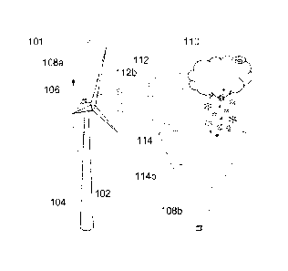
Figure la is a sketch illustrating a use scenario 101 of an embodiment of the
ar-
rangement suggested herein. The use scenario 101 incorporates a wind turbine
102 provided with the arrangement. The arrangement includes a lidar 108a, 108b
that may be mounted on the nacelle 106 or ground respectively, for instance,
such that the cone formed by the emitted beam 112, 114 can be targeted towards
predetermined or dynamically adjustable direction scanned by the lidar 108a,
108b. Lidar 108a has been configured so as to scan substantially in the
horizontal
direction whereas lidar 108b has been positioned on the ground and arranged to
scan in the vertical direction. It shall be clear to a skilled person that
e.g. the na-
celle 106, base, or the tower 104 of the wind turbine 102 may also be provided
with a lidar that is configured to emit its beam in a substantially vertical
direction
CA 02840622 2013-12-24
WO 2013/004893 PCT/F12012/050613
9
or diagonally relative to a reference plane such as the ground. The other
entities
of the arrangement (not shown in Figure la) may be located in connection with
the lidar entity 108a, 108b or be remotely disposed remaining, however,
operably
connectable therewith.
As mentioned hereinbefore, the lidar 108a, 108b may be a coherent (detection)
lidar, such as a coherent Doppler lidar (e.g. pulsed or continuous wave), or
an in-
coherent lidar such as incoherent Doppler lidar. In many use scenarios, a
coher-
ent heterodyne Doppler lidar may indeed be applied, for instance.
At least a portion of the electromagnetic energy transmitted by the lidar as a
beam of light may be backscattered due to particles such as dust, pollen, or
drop-
lets present in the atmosphere and moving at the same velocity as the ambient
wind. The velocity of the particles along the measurement beam direction
causes
a frequency shift in the backscattered signal that may be then applied by a
Dop-
pler lidar to estimate the wind speed.
A lidar may be utilized to obtain data about wind speed, turbulence, wind veer
and/or wind shear data in addition to being used for estimating the icing
condi-
tions in accordance with the present invention. Further, the lidar may be
located
on a suitable position such as the wind turbine rotor or nacelle to measure on-
coming horizontal winds in order to enable adjusting blades to protect compo-
nents and increase power, for example.
The applied laser may emit wavelength falling within the range of about 600 to
1700 nm, i.e. the wavelength may be about 1500 nm, for instance. A feasible
wavelength, cone angle and other measurement parameters, such as pulse width,
pulse energy, beam size, focus distance, and/or accumulation time etc., may be
selected use scenario ¨specifically.
For example, Windcube TM lidar (pulsed heterodyne) is an example of a Doppler
lidar that may be applicable in connection with the present invention
certainly
still depending on the particular embodiment and use scenario in question.
Backscattering and related data, i.e. wind parameters and/or icing conditions,
may be specifically measured at a predetermined number, i.e. one or more, of
heights (or generally distances) 112a, 114b as defined from a reference point
such as the lidar equipment itself. However, the use of e.g. a pulsed lidar
may be
CA 02840622 2013-12-24
WO 2013/004893 PCT/F12012/050613
preferred so that the backscattering information relative to a plurality of
heights
may be conveniently obtained without first strictly specifying the measurement
heights. A distance to the location of interest (e.g. the location of a wind
turbine
blade tip in maximum altitude, or the location of the nacelle/hub) may
translate
5 .. as tens or even hundreds of meters, or substantially the immediate
vicinity of the
lidar entity 108a, 108b, so the range is wide and depends on the embodiment.
With somewhat clear sky, backscattering is modest but in cloudy 110
conditions,
for example, the signal strength of the backscattered signal is stronger,
which
may be exploited in determining the icing potential at each height.
Fig. lb depicts a block diagram of an embodiment 121 of the proposed arrange-
ment with functional emphasis. Optional features of the embodiment are illus-
trated with rectangles having a broken outline.
The arrangement 121 is typically provided with one or more processing devices
capable of processing instructions and other data, such as one or more
micropro-
cessors, micro-controllers, DSPs (digital signal processor), programmable
logic
chips, etc. The processing entity 122 may thus, as a functional entity,
physically
comprise a plurality of mutually co-operating processors and/or a number of
sub-
processors connected to a central processing unit, for instance. The
processing
entity 122 may be configured to execute the code stored in a memory 124, which
may refer to the icing detection software and optionally other software such
as
counter-measure triggering software in accordance with the present invention.
The software may utilize a dedicated or a shared processor for executing the
tasks thereof. The code may be provided on a carrier medium such as a memory
card or an optical disc, or be provided over a communications network.
Similarly, the memory entity 124 may be divided between one or more physical
memory chips or other memory elements. The memory 124 may further refer to
and include other storage media such as a preferably detachable memory card, a
floppy disc, a CD-ROM, or a fixed storage medium such as a hard drive. The
memory124 may be non-volatile, e.g. ROM (Read Only Memory), and/or vola-
tile, e.g. RAM (Random Access Memory), by nature. The memory 124 may also
be at least partially integrated with the processing entity 122.
A lidar entity 108 is configured to emit the electromagnetic radiation
according
to the applied configuration, receive the backscattered signal and provide the
measurement data as such and/or in processed format to the processing entity
108
CA 02840622 2013-12-24
WO 2013/004893 PCT/F12012/050613
11
for further use. In some embodiments, the lidar entity 108 may also
incorporate
at least portion of the processing entity 122 and/or optionally further
illustrated
and/or other entities.
The UI (user interface) and/or a communications interface entity 138 may com-
prise a display, e.g. an (0)LED (Organic LED) display, and/or a connector to
an
external display or a data projector, and a keyboard/keypad or other
applicable
control input means (e.g. touch screen or voice control input, or separate
keys/buttons/knobs/switches) configured to provide the user of the entity with
practicable data visualization and/or arrangement control means. The UI may in-
clude one or more loudspeakers and associated circuitry such as D/A (digital-
to-
analogue) converter(s) for sound output, e.g. alert sound output, and a micro-
phone with A/D converter for sound input. The communications interface such as
at least one transceiver may incorporate e.g. a radio part including a
wireless
transceiver, such as WLAN (Wireless Local Area Network), Bluetooth or mobile
network (e.g. GSM/UMTS) transceiver for communication with external devices
such as sensors 136, monitoring devices, control devices, data capturing
devices
and/or a network infrastructure, and/or other wireless or wired data
connectivity
means such as one or more wired interfaces (e.g. LAN such as Ethernet, Fire-
wire, or USB (Universal Serial Bus)) for the similar purpose.
The temperature data utilized in determining the icing potential may be
obtained
by a number of sensors 136 integrated with or at least operatively connected
to
the processing entity 122 e.g. via the communications interface 138. Anti-
and/or
de-icing means 134 may be likewise provided and connected to the processing
entity 122.
On the right side of Figure lb, as separated by the broken bi-directional
arrows
from the rest of the arrangement 121, the entity 125 discloses few at least
logical-
ly noteworthy entities the arrangement 121 preferably includes and/or imple-
ments e.g. via combination of measurement data provided by lidar 108, meas-
urement data provided by at least temperature sensor 108, and the software exe-
cuted by the processing entity 122 and stored in memory 124. Parameter deter-
mination block 126 determines an indication of the backscattering signal
intensi-
ty such as CNR or other signal intensity -indicating parameter based on the
backscattered lidar signal for comparison. Received signal strength, or
'level',
may in some embodiments be directly used. The procedure may be executed by
the lidar 108 itself and/or the processing entity 122. Comparison block 128
refers
CA 02840622 2013-12-24
WO 2013/004893 PCT/F12012/050613
12
to comparing the measurement data and/or parameter derived therefrom with ref-
erence data to figure out the likelihood of obstacles such as clouds at the
meas-
ured distances. Indication determination block 130 calculates the indication
of
the icing potential on the basis of the comparison and further data such as
(tem-
perature) sensor data. The temperature data may be associated with own refer-
ence data. Triggering entity 132 is configured to trigger a procedure such as
de-
icing or anti-icing procedures. A triggering signal may be sent towards the
pro-
cedure-executing entity.
It is clear to a skilled person that the disclosed entity may comprise few or
nu-
merous additional functional and/or structural elements for providing
beneficial
communication, processing or other features, whereupon this disclosure is not
to
be construed as limiting the presence of the additional elements in any
manner.
One or more, e.g. all, constituent entities of the arrangement 121 may be
provid-
ed in a common housing thus forming a device. Alternatively, the arrangement
121 may be provided as multiple and at least operatively connectable units in-
cluding at least one physically separable entity selected from the group
consisting
of: a lidar entity, a main unit (comprising e.g. a processing entity and
memory), a
sensor such as a temperature sensor, and an anti/de-icing element.
As the backscattered signal intensity typically varies with the different
atmos-
pheric conditions, it may be used for data quality check. Data with intensity
low-
er than a predetermined threshold may be treated as bad quality data and be
dis-
carded. Backscattered signal intensity is generally higher when there are a
lot of
particles in the air. For example, small water droplets forming clouds and fog
represent a good scattering media for the laser beams of the lidar equipment.
Cloudy and foggy conditions in the volume of air probed by the lidar will thus
lead to high back scattered signal and signal strength.
Those conditions may lead to icing conditions in an atmosphere with low tem-
peratures. The lidar may be used to detect icing conditions by looking at
signal
intensity and temperature, for instance.
An embodiment of a procedure to detect icing conditions by measuring the
backscattered signal intensity and the temperature of the atmosphere and
compar-
ing them with the reference thresholds may be formulated as:
CA 02840622 2013-12-24
WO 2013/004893 PCT/F12012/050613
13
if S(x)> Tss(x) and Tail< Tsan 4 Icing conditions (1)
wherein Tss (x) may represent the threshold value for the backscattered signal
as
a function of distance, Tsair may represent the threshold value for the air
temper-
ature, Tair may represent the measured or otherwise estimated air temperature
(may be distance-specific) and S(x) the intensity of the measured or otherwise
es-
timated backscattered signal. The threshold values for the air temperature may
al-
so be distance-specific.
When the criteria are met for a certain distance Xice, the icing conditions
will be
detected and may be optionally further assumed happening at all heights x >
xice.
Icing conditions intensity at distance x may be considered to be proportional
to
S(x)- Ts, (x) and lair- TSair.
Figure 2 illustrates, at 201, merely exemplary data (dB) indicative of
backscatter-
ing signal intensity, such as CNR, in the case of varying conditions on a test
site
and related reference values (threshold values). The horizontal axis
represents al-
titude (or generally distance) and the vertical axis represents the intensity
deter-
mined utilizing the backscattered measurement signal captured by the lidar.
The
shown three curves represent the intensity indications of three different
condi-
tions, namely 'no ice' 204, 'ice far' 206, and 'ice near' 208, respectively,
where-
as the fourth curve 210 indicates the comparison reference (threshold). The
indi-
cations may have been originally determined for a number of distances and the
results may have been then connected resulting in the visualized curves. The
in-
dications may have been estimated for the intermediate distances by interpola-
tion, for example, in case no applicable number of true measurements was
readily
available. E.g. CNR may be considered, as a diagnostic of measurement quality
being thus somewhat equivalent to signal to noise ratio, but also applicable
in the
.. context of the present invention for evaluating cloudiness.
It is clearly visible in the figure how the shorter distance ¨relating
intensity val-
ues of 'ice near' curve 208 and the longer distance ¨relating intensity values
of
'ice far' curve 206 are, by a considerable margin, higher than the distance-
wise
matching values in the 'no ice' case as indicated by curve 204 or in the
reference
(threshold) curve 210. The reference 210 may have been theoretically and/or em-
pirically determined to imply conditions that serve as applicable threshold
for de-
cision-making. Optionally, a number of selected curve properties (e.g. shape,
CA 02840622 2013-12-24
WO 2013/004893 PCT/F12012/050613
14
size, etc.) may be utilized to determine a number of desired parameters or
indica-
tors.
The applied thresholds for both intensity and temperature may be tuned site-
specifically.
The logic for the method may be implemented via software code that may be fur-
ther delivered on a carrier medium such as optical disc or memory card, for ex-
ample. External sensor(s) or lidar-incorporated sensor(s) may be applied for
tem-
perature sensing. This kind of a method may be used both for assessment purpos-
es (occurrences of icing conditions) and system control (ice prevention
system)
Figure 3 discloses, by way of example only, a method flow diagram in accord-
ance with an embodiment of the present invention.
At 302, the arrangement for executing the method is obtained and configured,
for
example, via installation and execution of related hardware and/or software.
New
hardware and/or software may be installed at the use locations and/or the
exist-
ing, already available gear such as wind turbine ¨installed lidar may be
config-
ured or tailored according to the principles put forth herein. Execution
parameters
such as lidar emission and reception parameters (beam wavelength, pulse
length,
pulse energy, beam diameter, focus points (distances), and/or accumulation
time)
and/or sensor parameters (e.g. temperature sensor settings) may be set.
At 304, the lidar is applied to emit electromagnetic radiation, i.e. light
(visible or
non-visible) to the atmosphere and received the backscattered signal
therefrom.
At 306, e.g. the backscattered, captured signal may be analyzed to produce at
least one indication such as a number of parameters indicative of
backscattered
signal intensity such as CNR, for instance. The CNR and/or other parameter(s)
may be determined for a number of preselected distances (e.g. for the
distances
having the corresponding reference values available) and the lidar may have
been
configured accordingly to provide applicable measurement data. Alternatively,
a
number of distances under interest (e.g. the distances likely associated with
backscattering-causing aerosol such as cloud according to the received
backscat-
tering signals) may be dynamically determined through the utilization of a
pulsed
lidar and preferably substantially continuous reference data, for example.
15
At 308, the at least one indication such as a CNR parameter is compared with a
reference 320
that may have been stored in the executing arrangement earlier and is
optionally more or less
frequently updated, or the reference may be received from an external entity
such as a control
apparatus.
At 310, the icing potential 324 is determined by utilizing the indication of
signal intensity and
the reference (i.e. the comparison result), and an indication of the
temperature 322. For exam-
ple, the indication of temperature may be compared with a predetermined
temperature reference
(threshold).The indication of temperature may be obtained on the basis of
truly measuring or at
least estimating the temperature at the number of distances, or it may be
represent the temper-
ature obtained via some available, however non-optimum, sensor location that
still preferably
is as near to the locations of interest (at said number of distances) as
possible. In some embod-
iments, only e.g. a wind turbine tower, blade or e.g. nacelle may be provided
with a temperature
sensor, and the output thereof may be used as such and/or as a source for
estimating the tern-
perature at a number of distances through a number of applicable methods such
as extrapolation
and/or interpolation. An indication of the icing potential may be transmitted
to an external entity
and/or used to trigger an internal action in the arrangement such as de-icing
or anti-icing meas-
ure. The indication may be stored in a data log together with optional further
data such as tem-
perature and/or parameter such as CNR data, for example.
At 312, the method execution is ended. In many real-life scenarios the
execution of various
method items may be repeated and even parallel execution thereof is possible.
The execution
may be substantially continuous. For instance, new measurement data may be
gathered by the
lidar entity when the processing entity determines the icing potential
utilizing the already-ob-
tamed data.
The mutual ordering and overall presence of the method items of the method
diagrams disclosed
above may be altered by a skilled person based on the requirements set by each
particular use
scenario.
Consequently, a skilled person may, on the basis of this disclosure and
general knowledge,
apply the provided teachings in order to implement the scope of the present
invention as de-
scribed herein in each particular use case with necessary modifications,
deletions, and additions,
if any.
CA 2840622 2018-08-29
CA 02840622 2013-12-24
WO 2013/004893 PCT/F12012/050613
16
For example, provided that a lidar for transmitting electromagnetic radiation
to
the atmosphere and receiving the backscattered portion has already been provid-
ed in the target equipment such as a wind turbine, it may be supplemented with
at
least operatively coupled other necessary elements, such as the data
processing
entity, data transmission entity and/or sensor(s), for building up an
embodiment
of the arrangement in accordance with the present invention. In some embodi-
ments, the original lidar equipment may be simply re- reconfigured, i.e. repro-
grammed, to also act as the data processing entity, for instance, and even
differ-
ent data interfaces such as transceivers and/or sensor interfaces may be
integrated
with it.