Language selection

Search

Patent 2840699 Summary

Third-party information liability

Some of the information on this Web page has been provided by external sources. The Government of Canada is not responsible for the accuracy, reliability or currency of the information supplied by external sources. Users wishing to rely upon this information should consult directly with the source of the information. Content provided by external sources is not subject to official languages, privacy and accessibility requirements.

Claims and Abstract availability

Any discrepancies in the text and image of the Claims and Abstract are due to differing posting times. Text of the Claims and Abstract are posted:

  • At the time the application is open to public inspection;
  • At the time of issue of the patent (grant).
(12) Patent Application: (11) CA 2840699
(54) English Title: FULL WAVE LOW FLICKER LED LIGHT STRING
(54) French Title: GUIRLANDE LUMINEUSE A DEL A FAIBLE SCINTILLATION ET DOUBLE ALTERNANCE
Status: Deemed Abandoned and Beyond the Period of Reinstatement - Pending Response to Notice of Disregarded Communication
Bibliographic Data
(51) International Patent Classification (IPC):
  • F21K 09/00 (2016.01)
  • F21S 04/10 (2016.01)
(72) Inventors :
  • JANNING, JOHN L. (United States of America)
(73) Owners :
  • INC. JLJ
(71) Applicants :
  • INC. JLJ (United States of America)
(74) Agent: SMART & BIGGAR LP
(74) Associate agent:
(45) Issued:
(22) Filed Date: 2014-01-24
(41) Open to Public Inspection: 2015-02-08
Availability of licence: N/A
Dedicated to the Public: N/A
(25) Language of filing: English

Patent Cooperation Treaty (PCT): No

(30) Application Priority Data:
Application No. Country/Territory Date
14/026,685 (United States of America) 2013-09-13
61/863,864 (United States of America) 2013-08-08

Abstracts

English Abstract


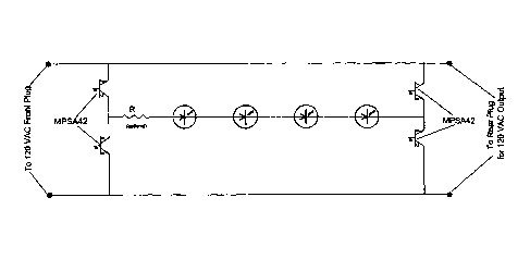
A split bridge circuit for rectifying the alternating current house supply
into direct current (D.C.), using bi-polar transistor as rectifying
devices. Using
the collector and emitter terminals of bi-polar
transistors results in a high forward voltage drop across the
transistors (particularly as compared to the voltage drop across diode
rectifiers in the prior art circuits), which reduces ripple significantly
and lessens, or even eliminates, the need for a series limiting resistor
in the circuit.


Claims

Note: Claims are shown in the official language in which they were submitted.


CLAIMS
1. A series wired light string comprising:
(a) at least 30 light emitting diodes (LED's) connected in electrical
series; and
(b) a split bridge rectifying circuit for powering the series connected
LED's, the split bridge rectifying circuit comprising:
(i) a first half bridge rectifying circuit formed of two
transistors as rectifying devices, using only the emitter
and collector terminals of the transistors, with the base
terminal not connected, and
(ii) a second half bridge rectifying circuit formed of two
transistors as rectifying devices, using only the emitter
and collector terminals of the transistors, with the base
terminal not connected;
wherein the series connected LED's are connected between
the first and second halves of the bridge rectifying circuit, and
wherein the first half bridge rectifying circuit is connected to a
first AC plug and the second half bridge rectifying circuit is
connected to a second AC plug.
2. The light string of claim 1, comprising 40 LED's connected in
electrical series.
3. The light string of claim 1, where 35 LED's are connected in electrical
series and an optional series resistance of approximately 750 ohms is
included in the series light string.

4. The light string of claim 1, where the two transistors of the first half
bridge rectifying circuit are mounted inside first AC plug and the two
rectifying transistors of the second half bridge rectifying circuit are
mounted inside the second AC plug.
5. The light string of claim 1, wherein the transistors of the first and
second split bridge rectifying circuits have a Vcbo of at least 180
volts.
6. The light string of claim 1, wherein the transistors of the first and
second split bridge rectifying circuits are bi-polar junction transistors.
7. The light string of claim 1, further comprising a third pair of rectifying
transistors disposed in the middle of the light string, using only the
emitter and collector terminals of the third pair of transistors, with the
base terminal not connected.
6

Description

Note: Descriptions are shown in the official language in which they were submitted.


CA 02840699 2014-01-24
FULL WAVE LOW FLICKER LED LIGHT STRING
BACKGROUND OF THE INVENTION
Present day Christmas lighting and decorating is now done mostly by using
light emitting diodes (LED's). LED light strings, with multiple LED's, are
usually wired in electrical series and powered by rectified alternating
current (A.C.). Some light strings are powered by half-wave rectification
using a single rectifier diode while others are powered by full-wave rectified
120 volt A.C. yielding better brightness and less flicker. Since light
emitting
diodes are DC devices and emit light according to the voltage applied, any
variation in voltage will cause a variation in brightness ¨ thus flickering.
This flicker is annoying to some people, even though at full-wave
rectification it occurs 120 times per second.
To achieve low flicker in an LED light string, it is necessary to rectify the
120 volt A.C. supply voltage into D.C. (direct current) as ripple free as
possible. This is usually done by using a full wave bridge rectifier circuit.
However, for light strings with end-to-end connectors, this usually means
four wires need to go "down the line". In U.S. Patent No. 6,972,528, Shao
teaches a circuit in which the full wave rectifier is split into two groups ¨
one
group of two rectifiers connected at the front end of the string and the other
group of two rectifiers connected at the end of the light string, i.e., a
split
bridge circuit. In U.S. Patent Nos. 7,649,322 and 8,072,152, Neuman et
al., teaches a similar split bridge approach, but uses an LED in series with
each rectifier diode in the split bridge structure.

CA 02840699 2014-01-24
SUMMARY OF THE INVENTION
The present invention provides a split bridge circuit for rectifying the
alternating current house supply into direct current (D.C.) using bi-polar
transistor as rectifying devices. Using specified terminals of the bi-polar
transistors results in a high forward voltage drop across the transistors
(particularly as compared to the voltage drop across diode rectifiers in the
prior art circuits), which reduces ripple significantly and lessens, or even
eliminates, the need for a series limiting resistor.
Other advantages, variations and other features of the invention will
become apparent from the drawings, the further description of examples
and the claims to follow.
BRIEF DESCRIPTION OF THE DRAWINGS
Figure 1 shows the split bridge circuit of the present invention employing
transistors, using the collector and emitter terminals of the transistors,
with
the base terminal of the transistors floating.
Figure 2 shows an embodiment of the split bridge circuit of the present
invention using a single pair of rectifying transistors in the center of the
light
string.
2

CA 02840699 2014-01-24
DETAILED DESCRIPTION OF THE PREFERRED EMBODIMENTS
Referring first to Figure 1, the split bridge circuit of the present invention
is
shown, employing transistors such as the MPSA42 or other low cost small
signal transistors with a suitable Vcbo of 180 volts or more. The base
terminal of the transistors float and do not get connected. Only the
collector and emitter terminals are used. To avoid having to use an
optional series resistor R, the number of light emitting diodes can be
increased to 40 LED's connected in electrical series, in the light string.
LED's used in Christmas light strings are usually rated at 20 milliamperes.
With 40 LED's in the light string of Figure 1, this works out nicely. As
known to those skilled in the art, strings can be made in multiples of 40
LED's, such as 80 or 120 lights in the string.
Because the forward voltage drop of such rectifying devices with the base
terminal floating is high at approximately about 6.5 volts, - compared to
approximately 0.7 volts for the standard silicon rectifier diodes ¨ and
because in a bridge rectifier circuit, current travels through two devices in
electrical series resulting in a total forward voltage drop of about 13 volts
for transistors, as compared to about 1.4 volts for rectifier diodes, the
ripple
found in prior art circuits is virtually eliminated, and the optional resistor
R
may not be needed. Such a light string would employ 35 LED's wired in
electrical series. As before, strings with multiples of 35 LED's can be made
having 70 or 105 lights.
3

CA 02840699 2014-01-24
,
The transistors at the front end of the light string can be mounted inside the
front 120 VAC plug. Likewise, the transistors at the end of the light string
can be mounted inside the rear plug.
The circuit shown in Figure 2 uses a single pair of rectifying transistors in
the center of the light string. This single rectifying transistor pair is used
in
both halves of the light string to rectify alternating current.
As mentioned previously, the resistor R shown in the figures is optional. It
may be necessary in some cases to provide a current limiting means and is
therefore used.
Although the invention has been described in detail in connection with the
exemplary embodiments, it should be understood that the invention is not
limited to the above disclosed embodiments. Rather, the invention can be
modified to incorporate any number of variations, alternations,
substitutions, or equivalent arrangements not heretofore described, but
which are commensurate with the spirit and scope of the invention.
Accordingly, the invention is not limited by the foregoing description or
drawings, but is only limited by the scope of the appended claims.
4

Representative Drawing
A single figure which represents the drawing illustrating the invention.
Administrative Status

2024-08-01:As part of the Next Generation Patents (NGP) transition, the Canadian Patents Database (CPD) now contains a more detailed Event History, which replicates the Event Log of our new back-office solution.

Please note that "Inactive:" events refers to events no longer in use in our new back-office solution.

For a clearer understanding of the status of the application/patent presented on this page, the site Disclaimer , as well as the definitions for Patent , Event History , Maintenance Fee  and Payment History  should be consulted.

Event History

Description Date
Inactive: IPC expired 2020-01-01
Inactive: IPC assigned 2019-10-15
Application Not Reinstated by Deadline 2019-01-24
Time Limit for Reversal Expired 2019-01-24
Deemed Abandoned - Failure to Respond to Maintenance Fee Notice 2018-01-24
Change of Address or Method of Correspondence Request Received 2018-01-12
Inactive: IPC expired 2016-01-01
Inactive: IPC removed 2015-12-31
Inactive: Cover page published 2015-02-16
Application Published (Open to Public Inspection) 2015-02-08
Inactive: IPC expired 2015-01-01
Inactive: IPC removed 2014-12-31
Inactive: Filing certificate - No RFE (bilingual) 2014-03-24
Inactive: IPC assigned 2014-03-06
Inactive: IPC assigned 2014-02-13
Inactive: First IPC assigned 2014-02-13
Inactive: Filing certificate - No RFE (bilingual) 2014-02-05
Application Received - Regular National 2014-02-04
Small Entity Declaration Determined Compliant 2014-01-24
Inactive: Pre-classification 2014-01-24

Abandonment History

Abandonment Date Reason Reinstatement Date
2018-01-24

Maintenance Fee

The last payment was received on 2016-08-10

Note : If the full payment has not been received on or before the date indicated, a further fee may be required which may be one of the following

  • the reinstatement fee;
  • the late payment fee; or
  • additional fee to reverse deemed expiry.

Patent fees are adjusted on the 1st of January every year. The amounts above are the current amounts if received by December 31 of the current year.
Please refer to the CIPO Patent Fees web page to see all current fee amounts.

Fee History

Fee Type Anniversary Year Due Date Paid Date
Application fee - small 2014-01-24
MF (application, 2nd anniv.) - small 02 2016-01-25 2015-08-04
MF (application, 3rd anniv.) - small 03 2017-01-24 2016-08-10
Owners on Record

Note: Records showing the ownership history in alphabetical order.

Current Owners on Record
INC. JLJ
Past Owners on Record
JOHN L. JANNING
Past Owners that do not appear in the "Owners on Record" listing will appear in other documentation within the application.
Documents

To view selected files, please enter reCAPTCHA code :


To view images, click a link in the Document Description column. To download the documents, select one or more checkboxes in the first column and then click the "Download Selected in PDF format (Zip Archive)" or the "Download Selected as Single PDF" button.

List of published and non-published patent-specific documents on the CPD .

If you have any difficulty accessing content, you can call the Client Service Centre at 1-866-997-1936 or send them an e-mail at CIPO Client Service Centre.


Document
Description 
Date
(yyyy-mm-dd) 
Number of pages   Size of Image (KB) 
Description 2014-01-23 4 151
Claims 2014-01-23 2 57
Abstract 2014-01-23 1 15
Drawings 2014-01-23 2 18
Representative drawing 2015-01-12 1 5
Filing Certificate 2014-02-04 1 179
Filing Certificate 2014-03-23 1 177
Courtesy - Abandonment Letter (Maintenance Fee) 2018-03-06 1 172
Reminder - Request for Examination 2018-09-24 1 116