Note: Descriptions are shown in the official language in which they were submitted.
CA 02840703 2013-12-30
PCT/KR2012/005780
[DESCRIPTION]
[Invention Title]
WIPER BLADE ASSEMBLY
[Technical Field]
The present invention relates to a wiper blade assembly, and more
particularly,
to a wiper blade assembly configured to facilitate coupling of a wiper arm and
a
connector member.
[Background Art]
A wiper blade assembly for wiping out the rain in case of rain or removing
foreign materials to secure a driver's visual field is disposed in a wind
shield of a
vehicle. The wiper blade assembly is connected to a wiper arm connected to a
driving
shaft connected to a wiper driving motor of the vehicle to be driven.
Here, the wiper arm and the wiper blade assembly are connected to each other
through a wiper connector part. In general, the wiper blade assembly includes
a clamp,
to which the connector member is coupled, and the wiper arm is coupled to the
connector member in a state in which the connector member is coupled to the
clamp.
Meanwhile, the wiper blade assembly may be classified into a conventional
type and a flat type according to the structure of a blade.
The conventional type wiper blade assembly is configured to apply an elastic
force to pressing a vehicular wind shield against a rubber strip making
contact with the
wind shield by coupling a plurality of yokes curved in an arc shape with an up-
down
structure and is widely used in the conventional wiper blade assembly of a
vehicle.
Meanwhile, the flat type wiper blade assembly includes a single elastic member
or a pair of elastic members, instead of yokes. The flat type wiper blade
assembly has a
simplified structure and is gradually increasingly distributed owing to its
pleasing
appearance when it is mounted on the vehicle.
FIG. 1 is a perspective view illustrating a portion of a conventional wiper
blade
assembly, specifically a flat type wiper blade assembly.
The wiper blade assembly 20 shown in FIG. 1 is a flat blade connected to a
wiper arm without a primary yoke and a secondary yoke. However, the present
1
CA 02840703 2013-12-30
PCT/KR2012/005780
invention that follows is not limited to the flat type wiper blade.
A blade rubber 23 making contact with the vehicular wind shield and a pair of
spoilers 21 are provided in the wiper blade assembly 20 shown in FIG. 1, and a
wiper
connector part 10 is disposed around the lengthwise center of the wiper blade
assembly
20. The wiper connector part 10 includes a connector member 40 to which a
wiper arm
(not shown) is coupled, and a clamp 30 coupled to the connector member 40 and
having
the connector member 40 received therein.
As shown in FIG. 1, the clamp 30 is preferably fabricated separately from the
wiper blade assembly 20. However, it will be appreciated that each of the
clamp 30 and
the connector member 40 is formed of a single member according to embodiment.
As described above, the conventional wiper blade assembly is configured such
that the clamp is provided to be coupled to a connector member and the clamp
and the
wiper arm is coupled to the connector member in a state in which the connector
member
is coupled to the clamp.
In this case, however, in order to allow the U-hook shaped wiper arm to be
coupled to the connector member, a space in which the wiper arm is capable of
freely
moving forward or backward is required. In a case where the space is not
secured, it is
difficult to achieve coupling of the wiper arm and the connector member.
[Disclosure]
[Technical Problems]
The present invention has been made in an effort to solve the problems of the
prior art, and it is an object of the present invention to provide a wiper
blade assembly
configured to facilitate connection of a wiper arm and a connector member.
[Technical Solution]
In accordance with an aspect of the present invention, the above and other
objects can be accomplished by providing a wiper blade assembly including a
wiper
connector part positioned at a predetermined lengthwise region, wherein the
wiper
connector part includes a connector member to which a wiper arm is coupled and
a
connector receiving part in which the connector member is received, and the
connector
receiving part includes a first hinge shaft shaped of a protrusion having a
predetermined
2
CA 02840703 2016-01-18
thickness on a first widthwise inner sidewall and a second hinge shaft shaped
of a
protrusion having a predetermined thickness on a second widthwise inner
sidewall.
The cross-sectional shape of the first hinge shaft or the second hinge shaft
includes a hinge main shaft and a hinge sub shift extending from the hinge
main shaft,
the hinge main shaft is a hinge shaft for coupling the connector member and
the
connector receiving part, and the hinge sub shift is a subsidiary shaft
serving as a stopper
in separating the connector member from the connector receiving part.
The connector receiving part may further include a lengthwise inner sidewall,
a
space having a predetermined size may be formed by the widthwise inner
sidewall and
the lengthwise inner sidewall, and the connector member may be received in the
space.
The connector member may include a wiper arm receiving part having a space of
a predetermined size, the wiper arm receiving part includes widthwise inner
sidewall and
lengthwise inner sidewalls, the space of a predetermined size is formed by the
second
widthwise inner sidewalls and the lengthwise inner sidewalls, and the wiper
arm is
received in the space.
The connector member may further include a hinge shaft fastening part to be
coupled to a first hinge shaft or a second hinge shaft of the connector
receiving part.
The hinge shaft fastening part may include a hinge shaft inserting part for
inserting the first hinge shaft or the second hinge shaft into the hinge shaft
fastening part
and a hinge shaft seating part to which the first hinge shaft or the second
hinge shaft is
coupled to be seated.
The hinge shaft inserting part may include an inserting part first end and an
inserting part second end, the hinge shaft inserting part is formed by a space
between the
inserting part first end and the inserting part second end, and when the
connector
member is separated from the connector receiving part, the inserting part
first end is fixed
by the hinge sub shift and the inserting part second end is spaced apart from
the inserting
part first end.
The thickness of the first hinge shaft may be a thickness ranging from a first
inner
sidewall in a widthwise direction of the connector receiving part to a portion
contacting a
U-shaped portion of a leading edge of the wiper arm, and a thickness of the
second hinge
shaft may be a thickness ranging from a second inner sidewall in the widthwise
direction
of the connector receiving part to the portion contacting the U-shaped portion
3
CA 02840703 2013-12-30
PCT/KR2012/005780
of the leading edge of the wiper arm.
[Advantageous Effects]
As described above, according to the present invention, the wiper arm and the
connector member are first coupled to each other and the connector member is
then
received in the connector receiving part. Therefore, a need for a space
required for
forward or backward movement may be eliminated in coupling the U-hook shaped
wiper arm to the connector member.
In addition, since the hinge shaft includes a hinge main shaft and a hinge sub
shift serving as a stopper, separation of the connector member from the
connector
receiving part can be facilitated.
[Description of Drawings]
In the figures:
FIG. 1 is a perspective view illustrating a portion of a conventional wiper
blade
assembly;
FIG. 2 is a perspective view of a wiper blade assembly according to an
embodiment of the present invention, specifically a flat type wiper blade
assembly.
FIG. 3 is a perspective view illustrating a wiper connector part of a wiper
blade
assembly according to the present invention;
FIG. 4 is a plan view illustrating a wiper connector part of a wiper blade
assembly according to the present invention;
FIG. 5 is a perspective view illustrating a connector member of a wiper blade
assembly according to the present invention;
FIG. 6 is a front view illustrating a connector member of a wiper blade
assembly according to the present invention;
FIG. 7 is a perspective view illustrating a wiper arm of a wiper blade
assembly
according to the present invention;
FIG. 8 is a front view illustrating a wiper arm of a wiper blade assembly
according to the present invention;
FIG. 9 is a perspective view illustrating a state in which a wiper arm and a
connector member are coupled to each other in a wiper blade assembly according
to the
4
CA 02840703 2013-12-30
PCT/KR2012/005780
present invention;
FIG. 10 is a front view illustrating the state in which a wiper arm and a
connector member are coupled to each other in a wiper blade assembly according
to the
present invention;
FIG. 11 is a perspective view illustrating a state in which a connector member
and a connector receiving part are coupled to each other in a wiper blade
assembly
according to the present invention;
FIG. 12 illustrates coupling of connector member and a connector receiving
part in a wiper blade assembly according to the present invention; and
FIG. 13 illustrates separation of connector member and a connector receiving
part in a wiper blade assembly according to the present invention.
[Mode for Invention]
Hereinafter, preferred embodiments of the present invention will now be
described in detail with reference to the accompanying drawings, such that
those skilled
in the art can easily practice the present invention.
Advantages and features of the present invention and methods of accomplishing
the same may be understood more readily by reference to the following detailed
description of exemplary embodiments and the accompanying drawings. The
present
invention may, however, be embodied in many different forms and should not be
construed as being limited to the exemplary embodiments set forth herein.
Rather, these exemplary embodiments are provided so that this disclosure will
be thorough and complete and will fully convey the concept of the invention to
those
skilled in the art, and the present invention will only be defined by the
appended claims.
Like reference numerals refer to like elements throughout the specification.
FIG. 2 is a perspective view of a wiper blade assembly according to an
embodiment of the present invention, specifically a flat type wiper blade
assembly.
Here, as described above, the wiper blade assembly may be largely classified
into a conventional type and a flat type according to the structure of a
blade. The
conventional type wiper blade assembly is configured to apply an elastic force
to
pressing a vehicular wind shield against a rubber strip making contact with
the wind
shield by coupling a plurality of yokes curved in an arc shape with an up-down
structure
5
CA 02840703 2013-12-30
PCT/KR2012/005780
and is widely used in the conventional wiper blade assembly of a vehicle.
Meanwhile,
the flat type wiper blade assembly includes a single elastic member or a pair
of elastic
members, instead of yokes. However, the present invention is not limited to
the flat type
wiper blade.
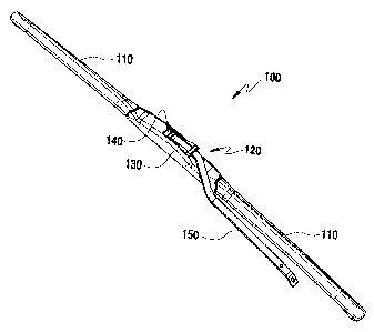
Referring to FIG. 2, the wiper blade assembly 100 according to the present
invention includes a rubber wiper strip (not shown) making contact with the
wind shield
of the vehicle and a pair of spoilers 110. In addition, a wiper connector part
120 is
positioned at a predetermined lengthwise region of the wiper blade assembly
100.
In FIG. 2, the wiper connector part 120 positioned at a lengthwise central
region of the wiper blade assembly 100 is illustrated. However, when
necessary, the
wiper connector part 120 may be positioned at a central region or a peripheral
region.
Therefore, the present invention does not limit the position of the wiper
connector part
120 to those illustrated herein.
Referring further to FIG. 2, in the wiper blade assembly 100 according to the
present invention, the wiper connector part 120 includes a connector member
130 to
which a wiper arm 150 is coupled and a connector receiving part 140 in which
the
connector member 130 is received.
Here, the wiper arm 150 is connected to a driving shaft connected to a wiper
driving motor of a vehicle side and the wiper blade assembly 100 may be driven
by
driving the wiper arm 150.
As shown in FIG. 2, the connector receiving part 140 may be integrally formed
with the wiper connector part 120. Alternatively, the connector receiving part
140 may
be fabricated separately from the wiper connector part 120 to then be fixed.
A configuration of the wiper blade assembly according to the present invention
will now be described in detail.
FIG. 3 is a perspective view illustrating a wiper connector part of a wiper
blade
assembly according to the present invention, and FIG. 4 is a plan view
illustrating a
wiper connector part of a wiper blade assembly according to the present
invention.
Referring to FIGS. 3 and 4, as described above, the wiper connector part 120
includes the connector receiving part 140 having a space of a predetermined
size, the
connector member 130 to which the wiper arm 150 is coupled is received in the
space
of the connector receiving part 140.
6
CA 02840703 2013-12-30
PCT/KR2012/005780
Referring to FIG. 4, the connector receiving part 140 includes inner sidewalls
141a and 14 I b of a widthwise direction (X) and inner sidewalls I42a and 142b
of a
lengthwise direction (Y), which forms the space of a predetermined size.
Here, hinge shafts 143a and 143b are formed in predetermined regions of the
widthwise (X direction) inner sidewalls 141a and 141b. In the present
invention, the
hinge shafts 143a and 143b may be protrusions having a predetermined thickness
(t).
In more detail, in the connector receiving part 140 according to the present
invention, the first hinge shaft 143a shaped of a protrusion having a
predetermined
thickness (t) is formed on the first widthwise inner sidewall 141a, and the
second hinge
shaft I43b shaped of a protrusion having a predetermined thickness (t) is
formed on the
second widthwise inner sidewall 141b.
The shape of the hinge shaft, that is, the protrusion having a predetermined
thickness (t), will later be described and the thickness of the hinge shaft,
that is, the
predetermined thickness (t), will later be described.
FIG. 5 is a perspective view illustrating a connector member of a wiper blade
assembly according to the present invention and FIG. 6 is a front view
illustrating a
connector member of a wiper blade assembly according to the present invention.
Referring to FIGS. 5 and 6, as described above, the connector member 130 is
received in the space of the predetermined size of the connector receiving
part 140. In
the present invention, after the wiper arm is coupled to the connector member
130, the
connector member 130 is received in the connector receiving part 140.
Here, the wiper arm is connected to a driving shaft connected to a wiper
driving
motor of a vehicle side and the wiper blade assembly 100 may be driven by
driving the
wiper arm.
The connector member 130 includes a wiper arm receiving part 133 having the
space of a predetermined size. Referring to FIG. 5, the wiper arm receiving
part 133
includes inner sidewalls 131a and 131b of a widthwise direction (X) and inner
sidewalls
132a and I32b of a lengthwise direction (Y), which forms the space of a
predetermined
size.
Here, the wiper arm receiving part 133 includes a fixed shaft 134 connecting
predetermined regions of the widthwise inner sidewalls 131a and 131b. The
fixed shaft
134 corresponds to a wiper arm fitting part for fitting a U-shaped part of a
leading edge
7
CA 02840703 2013-12-30
PCT/KR2012/005780
of a wiper arm (not shown) to be described later.
That is to say, the fixed shaft 134 connects the first widthwise inner
sidewall
131a and the second widthwise inner sidewall 131b to each other, and the U-
shaped part
of the leading edge of the wiper arm may be fitted to the fixed shaft 134 to
then be fixed.
Meanwhile, the connector member 130 may further include a wiper arm
supporting part 135 for preventing the wiper arm from deviating to an upward
direction
(Z of FIG. 5) of the connector member.
Referring further to FIGS. 5 and 6, the connector member 130 includes a hinge
shaft fastening part 136 to be coupled to a hinge shaft positioned at a
predetermined
region of the widthwise second inner sidewall of the connector receiving part.
The
hinge shaft fastening part 136 may include a hinge shaft inserting part 136a
for inserting
the hinge shaft into the hinge shaft fastening part and a hinge shaft seating
part 136b to
which the hinge shaft is coupled to be seated.
As shown in FIGS. 5 and 6, the hinge shaft inserting part 136a may include an
inserting part first end 137a and an inserting part second end 137b and may be
formed
by a space between the inserting part first end 137a and the inserting part
second end
137b.
FIG. 7 is a perspective view illustrating a wiper arm of a wiper blade
assembly
according to the present invention and FIG. 8 is a front view illustrating a
wiper arm of
a wiper blade assembly according to the present invention.
Here, the wiper arm may be provided as a component of the wiper blade
assembly, as described above. However, since the wiper arm is coupled to a
driving
shaft coupled to a wiper driving motor of a vehicle side, it may not be
provided as the
component of the wiper blade assembly. In the present invention, for the sake
of
convenient explanation, the wiper arm may be provided as the component of the
wiper
blade assembly.
Referring to FIGS. 7 and 8, the wiper blade assembly according to the present
invention is a general wiper arm 150, which may include a U-hook shaped part
151 at
its leading edge. As described above, the U-shaped part of the leading edge of
the wiper
arm may be fitted to the fixed shaft 134 positioned on the inner sidewall of
the wiper
arm receiving part to then be fixed.
Since the wiper arm is obviously known in the related art, a detailed
description
8
CA 02840703 2013-12-30
,
,
PCT/KR2012/005780
thereof will not be given.
FIG. 9 is a perspective view illustrating a state in which a wiper arm and a
connector member are coupled to each other in a wiper blade assembly according
to the
present invention and FIG. 10 is a front view illustrating the state in which
a wiper arm
and a connector member are coupled to each other in a wiper blade assembly
according
to the present invention.
As described above, the conventional wiper blade assembly is configured such
that a clamp is provided in the wiper blade assembly, the connector member is
coupled
to the clamp, and the wiper arm is coupled to the connector member in a state
in which
the connector member is coupled to the clamp.
Therefore, in this case, in order to allow the U-hook shaped wiper arm to be
coupled to the connector member, a space in which the wiper arm is capable of
freely
moving forward or backward is required. In a case where the space is not
secured, it is
difficult to achieve coupling of the wiper arm and the connector member.
In the present invention, however, as shown in FIGS. 9 and 10, the wiper arm
and the connector member are first coupled to each other, and the connector
member
coupled to the wiper arm is then received in the space of the connector
receiving part, as
will later be described.
That is to say, in the present invention, since the wiper arm and the
connector
member are first coupled to each other, and the connector member is then
seated in the
connector receiving part, the U-hook shaped wiper arm does not require a space
in
which it moves forward and backward to be coupled to the connector member.
The coupling of the wiper arm and the connector member of the wiper blade
assembly according to the present inventioOn will now be described in more
detail. The
connector member 130 includes the wiper arm receiving part 133 having the
space of a
predetermined size. Referring to FIG. 5, the wiper arm receiving part 133
includes the
inner sidewalls 131a and 131b of the widthwise direction (X) and the inner
sidewalls
132a and 132b of the lengthwise direction (Y), which forms the space of a
predetermined size, which is the same as described above.
Here, the wiper arm receiving part 133 includes a fixed shaft 134 connecting
predetermined regions of the widthwise inner sidewalls 131a and 131b. The
fixed shaft
134 connects the first widthwise inner sidewall 131a and the second widthwise
inner
9
CA 02840703 2013-12-30
=
PCT/KR2012/005780
sidewall 131b to each other and a U-shaped part of a leading edge of the wiper
arm may
be fitted to the fixed shaft 134 to then be fixed.
Meanwhile, the connector member 130 may further include a wiper arm
supporting part 135 to prevent the wiper arm from deviating to an upper
direction (Z of
FIG. 5) of the connector member.
FIG. 11 is a perspective view illustrating a state in which a connector member
and a connector receiving part are coupled to each other in a wiper blade
assembly
according to the present invention.
As described above, according to the present invention, the wiper arm and the
connector member are first coupled to each other and the connector member is
then
received in the space of the connector receiving part.
Here, when the connector member is received in the space of the connector
receiving part, as a hinge shaft fastening part of the connector member and a
hinge shaft
of the connector receiving part are coupled to each other, the connector
member and the
connector receiving part are coupled to each other.
In more detail, as described above, the connector member 130 according to the
present invention includes a hinge shaft fastening part 136. The hinge shaft
fastening
part 136 includes a hinge shaft inserting part 136a for inserting the hinge
shaft into the
hinge shaft fastening part and a hinge shaft seating part 136b to which the
hinge shaft is
coupled to be seated. Therefore, after the hinge shaft fastening part of the
connector
member is inserted into the hinge shaft inserting part, it is seated in the
hinge shaft
seating part in an interference fit manner, thereby coupling the connector
member and
the connector receiving part to each other.
As described above, the hinge shaft is shaped of a protrusion having a
predetermined thickness (t).
That is to say, the general connector member includes a hinge shaft to be
coupled to the connector receiving part. In this case, however, the hinge
shaft is shaped
of a continuous cylinder connecting inner walls, rather than a protrusion
having a
predetermined thickness.
Since the general wiper blade assembly is configured such that the connector
member is first coupled to the clamp and the wiper arm is then coupled to the
connector
member in a state in which the connector member is coupled to the clamp, that
is to say,
CA 02840703 2013-12-30
s
,
PCT/KR2012/005780
since the connector member is first coupled to the clamp, the coupling of the
connector
member is not affected by the wiper arm. Therefore, the hinge shaft may have a
continuously cylindrical shape.
However, in the present invention, the wiper arm and the connector member are
5 first
coupled to each other, and the connector member coupled to the wiper arm is
then
received in the space of a predetermined size of the connector receiving part,
that is to
say, the connector member and the wiper arm are first coupled to each other
and then
coupled to the connector receiving part, the coupling of the connector member
is
affected by the wiper arm.
10
Eventually, in the present invention, in a case where the hinge shaft has a
shape
of a continuous cylinder connecting inner sidewalls, the connector member and
the
connector receiving part are not coupled to each other by being closed by the
U-shaped
part of the leading edge of the wiper arm.
Therefore, in the present invention, in order to allow the U-shaped part of
the
15 leading
edge of the wiper arm to pass the hinge shaft, the hinge shaft is configured
to
have a non-continuous protrusion having a predetermined thickness, rather than
the
continuous cylinder.
As described above, the thickness of the hinge shaft should be enough to
prevent the hinge shaft from being closed by the U-shaped part of the leading
edge of
20 the wiper
arm to allow the U-shaped part of the leading edge of the wiper arm to pass
the hinge shaft. For example, the thickness of the hinge shaft may be a
thickness
ranging from the first widthwise inner sidewall or the second widthwise inner
sidewall
of the connector receiving part to the U-shaped part of the leading edge of
the wiper
arm.
25 FIG. 12
illustrates coupling of connector member and a connector receiving
part in a wiper blade assembly according to the present invention and FIG. 13
illustrates
separation of connector member and a connector receiving part in a wiper blade
assembly according to the present invention.
First, as shown in FIG. 12, the connector member and the connector receiving
30 part are
coupled to each other such that the hinge shaft of the connector receiving
part is
inserted into the hinge shaft inserting part and then seated in the hinge
shaft seating part
in an interference fit manner, thereby coupling the connector member and the
connector
11
CA 02840703 2013-12-30
PCT/KR2012/005780
receiving part to each other.
Here, as shown in FIG. 12, a cross-sectional shape of the hinge shaft 143b
according to the present invention includes a hinge main shaft 143b' and a
hinge sub
shift 143b" extending from the hinge main shaft 143b'. The hinge main shaft
143b' is a
hinge shaft for coupling the connector member and the connector receiving
part, and the
hinge sub shift 143b" is a subsidiary shaft serving as a stopper in separating
the
connector member from the connector receiving part, as will later be
described.
Next, referring to FIG. 13D, the connector member and the connector receiving
part can be easily separated by increasing a space between the inserting part
first end
137a and the inserting part second end 137b.
That is to say, the increasing of the space between the inserting part first
end
137a and the inserting part second end 137b may include increasing an
insertion space
of the hinge shaft inserting part 136a. Therefore, the hinge shaft coupled in
the
interference fit manner can be easily separated by the hinge shaft inserting
part having
the increased inversion space.
In more detail, as described above, the hinge main shaft is a hinge shaft for
coupling the connector member and the connector receiving part, and the hinge
sub shift
143" is a subsidiary shaft serving as a stopper in separating the connector
member from
the connector receiving art. As shown in FIG. 13, when a wiper blade is
rotated, the
hinge sub shift 143" and the inserting part first end 137a are brought into
contact with
each other. Thereafter, if the wiper blade is rotated with a stronger force,
the inserting
part first end 137a is fixed by the hinge sub shift 143". However, the
inserting part
second end 137b that is not fixed by the hinge sub shift 143" is gradually
spaced apart
from the inserting part first end 137a.
That is to say, when the wiper blade is rotated, the hinge sub shift 143"
fixes the
inserting part first end 137a, but the inserting part second end 137b is not
fixed. Thus,
when the wiper blade is rotated by continuously applying a force, the
inserting part
second end 137b is gradually spaced apart from the inserting part first end
137a, which
means that the insertion space of the hinge shaft inserting part 136a is
increased.
Therefore, the hinge shaft coupled in the interference fit manner can be
easily separated
by the hinge shaft inserting part having the increased insertion space.
As described above, in the present invention, the wiper arm and the connector
12
CA 02840703 2016-01-18
member are first coupled to each other, and the connector member coupled to
the wiper
arm is then received in the space of the connector receiving part, an
unnecessary space
in which the U-hook shaped wiper moves forward and backward to be coupled to
the
connector member may be eliminated.
In addition, the hinge shaft includes a hinge main shaft and a hinge sub shift
serving as a stopper, separation of the connector member from the connector
receiving
part can be facilitated.
Although the foregoing embodiments have been described to practice the road
sign reflector and the manufacturing method thereof according to the present
invention,
these embodiments are set forth for illustrative purposes. The scope of the
claims should
not be limited by the preferred embodiments set forth herein, but should be
given the
broadest interpretation consistent with the description as a whole.
13