Note: Descriptions are shown in the official language in which they were submitted.
CA 02840718 2015-04-27
1 TITLE OF THE INVENTION
2 [0001] Plug with Pressure Release Valve
3 APPLICANT(S)/INVENTOR(S)
4 [0002] Inventor One:
Richard E. Larson
6 Citizenship: U.S.A.
7 Residence: 9020 Meadow Way
8 Victoria, MN 55386-4518
9 [0003] Inventor Two:
Steven R. Cole
11 Citizenship: U.S.A.
12 Residence: 614 Brookmere Drive
13 Collierville, TN 38017-6878
14 CROSS REFERENCE TO RELATED APPLICATIONS
[0004] Not applicable.
16 STATEMENT REGARDING FEDERALLY SPONSORED RESEARCH OR
17 DEVELOPMENT
18 [0005] Not applicable.
19 REFERENCE TO COMPACT DISC(S)
[0006] Not applicable.
21 BACKGROUND OF THE INVENTION
22 [0007] 1. Field of the Invention: The present invention relates,
in general, to plugs for
23 use in pipe systems and, in particular, to a pneumatic plug for use in
pipe systems, in which
24 the plug has a pressure release valve.
[0008] 2. Information Disclosure Statement: Drain, waste, and vent ("DWV")
pipe or
26 plumbing systems often include access openings or ports that allow the
interior of the pipes
27 of the pipe system to be inspected and/or cleaned. Likewise, sewer
systems often include
28 sewer pipes that empty into manholes or catch basins through openings or
ports in the
29 manhole or catch basin chambers. Access opening configurations for such
pipe systems can
vary in size and shape, although many configurations are standardized. In one
common
31 configuration, an access opening (often referred to as a "clean-out") is
provided at the end
32 of a relatively short section of cylindrical pipe that extends away from
the axis of the main
- 1 -
CA 02840718 2015-04-27
1 pipe section. Clean-outs may extend from a main pipe section at any
angle. Those that
2 extend approximately 90 degrees from the main pipe section are commonly
called "clean-
3 out tees" (referring to the T-shape created by the intersecting pipe
sections). Other access
4 openings include, but are not limited to, roof vents, storm drains,
closet bends, and pipe
ends, and the sewer pipe openings or ports in a manhole or catch basin
chamber.
6 [0009] Access openings may also be used to test the integrity of
the pipe system. Such
7 a test is conducted by placing temporary plugs into all openings of the
DWV system to
8 create a closed system, and then pressurizing the now-closed system with
a fluid, such as
9 water or air, for a period of time to determine if the DWV system is leak
free, in which case
it will hold a rated pressure for the test duration. After successful testing,
the plugs are
11 removed. Such temporary plugs can generally be categorized into
mechanical plugs and
12 pneumatic plugs. Existing mechanical plugs typically include devices
that seal pipe systems
13 via mechanical activation, such as by turning a threaded connection
member to expand an
14 elastomeric ring that seals an inner surface of a pipe section. Existing
pneumatic plugs
include elongate elastomeric bladders that are attached directly to a source
of fluid such as,
16 typically and preferably, an air source. The bladders are inserted into
the pipe system
17 through the clean-outs or other access openings and are then inflated
with the fluid so as to
18 seal the pipe section as the bladder expands within the pipe. After
testing, the temporary
19 plugs are deflated or deactivated and then removed from the pipe system.
In addition to the
testing of DWV systems and/or sewer systems, it is often desired to seal a
pipe line during a
21 maintenance function, in which flow through the pipe is blocked for
maintenance purposes
22 even though pressure testing of the pipe system is not being performed.
23 [0010J Although some existing pneumatic plugs may display a
maximum inflation
24 pressure on the outside of the bladder, this does not provide protection
for overinflation, but
instead relies on the diligence of the operator and the existence and accuracy
of an air inlet
26 pressure gauge. If the elastomeric bladders of such pneumatic plugs
become overinflated,
27 problems could occur. The result when over-inflation occurs can be
damage to the plug,
28 damage to the pipe, inconvenience and delay of the testing process, or
injury to the user if
29 the plug explodes due to over-inflation. Known prior art solutions to
this problem involve
using an external pressure regulator or external pressure release device on
the air inlet, but
31 these solutions are cumbersome and are often ignored by operators, or
the operator may be
32 careless when using such regulators or pressure release valves. Pressure
regulators do work
33 but increase the inflation time, and they must be accurately set prior
to use. Furtheiniore,
34 each different type of pneumatic plug typically requires a different
pressure setting to be
- 2 -
CA 02840718 2015-04-27
1 made by the operator to accommodate plugs for different pipe diameters.
External pressure
2 release valves are also known to work, but are subject to failure if they
become plugged and
3 are typically unreliable for making accurate pressure settings. Such
external pressure
4 release valves must also be attached between the plug and the inflation
hose, are often
bulky, and also slow down the inflation process.
6 [0011] Some existing pneumatic plugs include integrated pressure
release devices.
7 However, such prior art pressure release devices tend to leak, do not
provide repeatable
8 results, and may disrupt testing of the pipe system. Specifically, some
pneumatic plugs
9 include release valves that have mechanical springs and seals, and have
been found to be
prone to fouling and often tend to collect contamination. Other pneumatic
plugs include
11 release valves that are positioned on the backside of the elastomeric
bladder, venting into
12 the pipe system being tested, and tend to expel the plug out of the pipe
system and clean-out
13 access, thereby disrupting the testing process.
14 [0012] One example of such a prior art plug is that made by Cherne
Industries, Inc.,
Minneapolis, Minnesota, U.S.A., and sold under the trademark LONG TEST-BALL.
This
16 pneumatic plug has the disadvantage of having mechanical parts including
springs and seals
17 that tend to leak or not accurately release pressure at a repeatably
accurate value.
18 [0013] Another pneumatic plug is made by GT Water Products, Inc.,
Moorpark,
19 California, U.S.A., and sold under the trademark SAFE-T-SEAL, and has a
pressure release
on the bottom of the plug, remote from the pressurizing inlet and venting into
the pipe
21 system, which can cause the plug to be forced out of the pipe as the
relieved pressure expels
22 into the sealed pipe system being tested.
23 [0014] Still another prior art pneumatic plug is that disclosed in
U.S. Patent 7,597,118
24 (issued October 9, 2009), in which a portion of the elastomeric bladder
is elastically
deflected to unblock a pressure release channel when the bladder becomes
overinflated.
26 [0015] As a result, there is a need for an improved pneumatic plug
for use with a pipe
27 section having a generally cylindrical internal pipe wall. The pneumatic
plug should be
28 easy to use and should not require the operator to make additional
settings or readings. It
29 should be reliable, provide repeatable results, and it should not
require additional external
equipment or otherwise disrupt testing of the pipe system.
31 [0016] It is therefore desirable to have a pneumatic plug for use
in pressure testing a
32 pipe system, in which the plug includes a pressure release valve in its
inflation end remote
33 from the pressurized pipe system being tested, wherein the pressure
release valve provides a
- 3 -
CA 02840718 2015-04-27
1 repeatable chosen release pressure, and in which the pressure release
valve is more reliable
2 than prior art pneumatic plug pressure release valves.
3 BRIEF SUMMARY OF THE INVENTION
4 [0017] Several preferred embodiments of the pressure release valve
of the present
invention are disclosed as a part of a pneumatic plug. The common feature of
all
6 embodiments is that an elastomeric seal stretchingly surrounds a portion
of a valve core of
7 the pressure release valve of the plug, and the seal, being under hoop
stress around the
8 portion of the valve core, seals a pressure release outlet until pressure
within the plug
9 overcomes the hoop stress of the seal so that excess fluid pressure
within the plug is allowed
to escape from an interior void of the plug's bladder when the plug's bladder
becomes
11 overinflated.
12 [0018] In accordance with an aspect of an embodiment, there is
provided a plug for use
13 in sealing a pipe having a generally cylindrical internal pipe wall,
said plug comprising an
14 inflatable bladder having an interior void defined within said bladder;
said plug further
comprising a pressure release valve being mounted into an end of said plug,
said pressure
16 release valve including: (a) a valve core having a pressure release
passageway therethrough,
17 said pressure release passageway having a pressure release inlet in
selective fluid
18 communication with said interior void and further having a pressure
release outlet in fluid
19 communication with an exterior environment outside said bladder, said
pressure release
inlet and said pressure release outlet being joined by a bore through said
valve core; (b) an
21 elastomeric seal having a first seal portion always under hoop stress
about a portion of said
22 valve core and selectively sealing said pressure release outlet from
said exterior
23 environment, wherein, when overinflation of said bladder occurs, said
first seal portion
24 becomes elastically deflected to unseal said pressure release outlet
from said exterior
environment and thereby allow excess fluid pressure within said bladder to be
released
26 through said pressure release passageway and out said pressure release
outlet into said
27 exterior environment, said hoop stress causing said first seal portion
to reseal said pressure
28 release outlet from said exterior environment after sufficient excess
fluid pressure within
29 said bladder has been released.
[0019] It is an object of the present invention to provide a plug for use
in pressure
31 testing a pipe system, in which the plug includes a pressure release
valve in an inflation end
32 of the plug remote from the pressurized pipe system being tested. It is
a further object of
33 the present invention that the pressure release valve provide a
repeatable chosen release
34 pressure, in which a given design and structure of the pressure release
valve can be easily
- 4 -
CA 02840718 2015-04-27
1 and simply adapted to accommodate different desired release pressures,
and in which the
2 pressure release valve is more reliable than prior art pneumatic plug
pressure release valves.
3 BRIEF DESCRIPTION OF THE SEVERAL VIEWS OF THE DRAWING
4 Fig. 1 is a view showing a pneumatic plug with pressure release valve
of the
present invention inserted into a pipe.
6 Fig. 2 is a sectional view taken along a diameter of a first
embodiment of the
7 present invention, with the pressure release valve of the first
embodiment shown in outline.
8 Fig. 3 is an end view of the first embodiment of the present
invention, taken
9 substantially along the line 3-3 shown in Fig. 2.
Fig. 4 is an enlarged partial end view of the first embodiment of the present
11 invention, showing a portion of the end view of Fig. 3 and being taken
substantially along
12 the line 4-4 shown in Fig. 2.
13 Fig. 5 is a partial sectional view of the first embodiment of the
present invention,
14 taken along a diameter of the pressure release valve of the first
embodiment, with the
sectional view being taken substantially along the line 5-5 shown in Fig. 3
and with the
16 Schrader inflation valve being shown in dotted outline for clarity.
17 Fig. 6 is a partial sectional view of the first embodiment of the
present invention,
18 taken along a different diameter of the pressure release valve of the
first embodiment than
19 that shown in Fig. 5, with the sectional view being taken substantially
along the line 6-6
shown in Fig. 3, and also showing release of overinflation pressure by elastic
deflection of
21 the elastomeric seal.
22 Fig. 7 is a side view of the valve core of the first embodiment of
the present
23 invention with a sectional view of the elastomeric seal prior to fitting
onto the valve core so
24 as to cause the seal to have hoop stress.
Fig. 8 is a partial side sectional view of the second embodiment of the
present
26 invention, taken along a diameter of the pressure release valve of the
second embodiment,
27 with the Schrader inflation valve being shown in dotted outline for
clarity.
28 Fig. 9 is an end view of the second embodiment of the present
invention, taken
29 substantially along the line 9-9 shown in Fig. 8.
Fig. 10 is a transverse sectional view of the second embodiment of the present
31 invention, taken substantially along the line 10-10 shown in Fig. 11.
32 Fig. 11 is a partial sectional view of the second embodiment of the
present
33 invention, taken along a diameter of the pressure release valve of the
second embodiment,
- 5 -
CA 02840718 2015-04-27
=
1 and with the Schrader inflation valve being shown in dotted outline for
clarity.
2 Fig. 12 is a partial sectional view of the second embodiment of
the present
3 invention, similar to Fig. 11 but showing release of overinflation
pressure by elastic
4 deflection of the elastomeric seal.
Fig. 13 is a side view of the valve core of the second embodiment of the
present
6 invention with a sectional view of the elastomeric seal prior to fitting
onto the valve core so
7 as to cause the seal to have hoop stress.
8 Fig. 14 is a partial side sectional view of the third embodiment
of the present
9 invention, taken along a diameter of the pressure release valve of the
third embodiment.
Fig. 15 is a partial sectional view of the third embodiment of the present
11 invention, taken along a diameter of the pressure release valve of the
second embodiment
12 and with some parts of the Schrader inflation valve insert being removed
for clarity.
13 DETAILED DESCRIPTION OF THE INVENTION
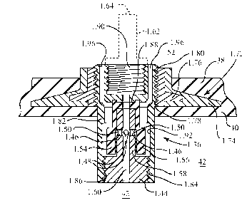
14 100201 Referring to the figures of the drawings, various preferred
embodiments of the
present invention are shown. As seen best in Fig. 1, all embodiments of the
present
16 invention are plugs 30 for use in sealing a pipe 32 having a generally
cylindrical internal
17 pipe wall 34, and the difference between the different embodiments is
the structure of the
18 pressure release valve (1.36, 2.36, 3.36) that is mounted into one end
38 of the plug 30. As
19 with prior art plugs, the plug 30 preferably may have a plurality of
well-known ribs 28
encircling the plug to provide improved sealing of the plug 30 with the pipe
wall 34 in a
21 manner well-known to those skilled in the art. There are many
similarities between the
22 various embodiments, and only the differences between the embodiments
will be discussed
23 in detail, it being understood that similar structure for the various
embodiments serves
24 similar purpose. The reference numerals for the various parts of the
embodiments shall be
understood to have a prefix identifying the particular embodiments (e.g.,
"1.", "2.", "3.",
26 etc.) and a suffix identifying the particular structure (e.g., "36",
etc.), such that reference
27 numerals with the same suffix are understood to be similar structure
particular to each of the
28 different embodiments (e.g., "1.36", "2.36", "3.36"). Reference numerals
without a prefix
29 (e.g., "30") shall be understood to indicate structure that is
substantially the same for all
embodiments.
31 [0021] The plugs of all embodiments are substantially similar, and a
description of the
32 representative one shown in Figs. 1 and 2 suffices for all embodiments.
As shown in Fig. 1,
33 plug 30 includes an inflatable bladder 40 having an interior void 42
defined within the
34 bladder 40. As shown in the drawing figures, common to all embodiments
of pressure
- 6 -
CA 02840718 2015-04-27
1 release valve 1.36, 2.36, 3.36 is that they each include a valve core
1.44, 2.44, 3.44,
2 preferably constructed of brass for durability, respectively having one
or more pressure
3 release passageways 1.46, 2.46, 3.46 therethrough, each having a pressure
release inlet 1.48,
4 2.48, 3.48 being in fluid communication with interior void 42 and with
each respective
pressure release passageway 1.46, 2.46, 3.46 also respectively having a
pressure release
6 outlet 1.50, 2.50, 3.50 in fluid communication with an exterior
environment 52 outside of
7 bladder 40. It should be understood that other materials, such as
aluminum, steel, etc.,
8 could be used to construct the valve core, but brass is the preferred
material. Preferably,
9 pressure release passageways 1.46, 2.46, 3.46 are formed by a pair of
transverse bores
through valve cores 1.44, 2.44, 3.44 at right angles with respect to each
other, thereby
11 producing four angularly-spaced pressure release passageways for the
valve cores 1.44,
12 2.44, 3.44. Experimental prototypes of pressure release valves 1.36,
2.36, 3.36 were
13 constructed with bores 1.46 having a diameter of 0.0785 inch (0.199 cm)
and with bores
14 2.46, 3.46 having a diameter of 0.100 inch (0.254 cm).
[0022] All embodiments of the pressure release valve 1.36, 2.36, 3.36 of
the present
16 invention have an elastomeric seal 1.54, 2.54, 3.54 respectively having
a first seal portion
17 1.56, 2.56, 3.56 under hoop stress about a respective portion 1.58,
2.58, 3.58 of the valve
18 core 1.44, 2.44, 3.44 and respectively selectively sealing the pressure
release outlet 1.50,
19 2.50, 3.50 from exterior environment 52 outside of bladder 40 such that,
when overinflation
of the bladder occurs, the first seal portion 1.56, 2.56, 3.56 becomes
elastically deflected, in
21 a manner hereinafter described in detail, to unseal the pressure release
outlet 1.50, 2.50,
22 3.50 from the exterior environment 52 so as to allow excess fluid
pressure within the
23 bladder to be released through the pressure release passageway 1.46,
2.46, 3.46 and out the
24 pressure release outlet 1.50, 2.50, 3.50 into the exterior environment
52. After sufficient
excess fluid pressure within the bladder has been released, the hoop stress of
the elastomeric
26 seal 1.54, 2.54, 3.54 then causes the first seal portion 1.56, 2.56,
3.56 to reseal the pressure
27 release outlet 1.50, 2.50, 3.50 from the exterior environment 52 in a
manner hereinafter
28 described in detail.
29 [0023] Preferably, all embodiments of the pressure release valve
1.36, 2.36, 3.36 of the
present invention include an inflation passageway 1.60, 2.60, 3.60 through the
valve and in
31 fluid communication with interior void 42, with the inflation passageway
1.60, 2.60, 3.60
32 preferably being axially disposed in the valve core 1.44, 2.44, 3.44,
and with an inflation
33 valve 1.62, 2.62, 3.62 being interposed between the inflation passageway
and the exterior
34 environment, in a manner hereinafter described in detail. Preferably, in
each embodiment,
- 7 -
CA 02840718 2015-04-27
1 the inflation valve is a well-known Schrader valve having a depressible
stem 1.64, 2.64,
2 3.64 that, in a manner well-known to those skilled in the art, opens the
Schrader valve
3 during inflation of the bladder 40 and that, when released, closes the
Schrader valve after
4 inflation, thereby causing fluid pressure to be retained within the
inflated bladder 40 during
testing of the pipe system. In all preferred embodiments of the pressure
release valve 1.36,
6 2.36, 3.36 of the present invention, the pressure release inlets 1.48,
2.48, 3.48 open into the
7 inflation passageway 1.60, 2.60, 3.60 so that the inflation path into the
void 42 and the
8 deflation of void 42 through passageways 1.46, 2.46, 3.46 is through the
common fluid
9 communication inflation passageway 1.60, 2.60, 3.60, thereby placing
pressure release
passageways 1.46, 2.46, 3.46 into fluid communication with void 42 through
inflation
11 passageway 1.60, 2.60, 3.60. The term "Schrader valve", as used herein,
shall be
12 understood not to mean a specific inflation valve from a particular
vendor, but instead the
13 term "Schrader valve" is used generically to refer to well-known so-
called "tank valves"
14 that provide for inflation from an air source that often has a hose that
may be threadedly
received upon external threads of the valve, with such valves typically having
an axial valve
16 stem that, when the stem is depressed into the valve, allow pressure to
be released through
17 the valve.
18 [0024] It should be noted that, in all embodiments, first seal
portion 1.56, 2.56, 3.56
19 preferably has one or more closed ribs 1.66, 2.66, 3.66 (shown somewhat
exaggerated in the
drawings for purposes of illustration, and best seen in Figs. 7 and 13) that
extend radially
21 inward to engage portion 1.58, 2.58, 3.58 of the valve core 1.44, 2.44,
3.44, so as to form a
22 better sealing of the pressure release outlets 1.50, 2.50, 3.50. In all
embodiments of
23 pressure release valve 1.36, 2.36, 3.36, both elastomeric seal 1.54,
2.54, 3.54 and valve core
24 1.44, 2.44, 3.44 are preferably substantially cylindrically symmetrical.
It should be further
noted that, in all embodiments of pressure release valve 1.36, 2.36, 3.36, the
inner diameter
26 1.58, 2.58 of first seal portion 1.56, 2.56 is less than the outer
diameter 1.70, 2.70 of portion
27 1.58, 2.58 of the valve core 1.44, 2.44 prior to stretchingly fitting
elastomeric seal 1.54, 2.54
28 onto valve core 1.44, 2.44 (see Figs. 7 and 13). As hereinafter
explained, the structure of
29 seal 2.54 and valve core 2.44 is the same as the structure of seal 3.54
and valve core 3.44,
such that Fig. 13 suffices for showing the structure of both the second and
third
31 embodiments of pressure release valve 2.36, 3.36. Because the inner
diameter of the first
32 seal portion of the unstretched elastomeric seal is smaller than the
outer diameter of the
33 portion of the valve core that is engaged by the first seal portion, the
first seal portion of the
34 elastomeric seal is caused to be under hoop stress about the valve core
when fitted thereon,
- 8 -
CA 02840718 2015-04-27
1 thereby causing the elastomeric seal to selectively seal the pressure
release outlet 1.50, 2.50,
2 3.50 from the exterior environment 52 in a manner hereinafter described
in detail.
3 [0025] With all embodiments, elastomeric seal 1.54, 2.54, 3.54 is
preferably made of
4 rubber having characteristics of a preferred tensile strength at least
2800 pounds minimum,
a preferred durometer rating of 52 Shore A (+/- 4), and an elongation rating
of 500% (+/
6 50). The radial thickness of first seal portion 1.56, 2.56, 3.56
preferably has a thickness of
7 about 0.100 inch to about 0.200 inch (about 0.254 cm to about 0.508 cm),
which yields a
8 pressure release value when installed on a valve core of between about 5
psig and 45 psig.
9 It will be understood that the pressure release value is determined by
the characteristics of
the rubber used for elastomeric seal 1.54, 2.54, 3.54, the radial thickness of
first seal portion
11 1.56, 2.56, 3.56, and the hoop stress of first seal portion 1.56, 2.56,
3.56 around portion
12 1.58, 2.58, 3.58 of valve core 1.44, 2.44, 3.44. The hoop stress is
understood to be
13 determined by the relative dimensions of the valve core's outer diameter
(e.g., outer
14 diameter 1.70, 2.70 of portion 1.58, 2.58 of the valve core 1.44, 2.44)
as compared to the
seal's inner diameter (e.g., inner diameter 1.58, 2.58) (i.e., the amount that
the seal has to be
16 stretched to go on to the valve core). For example, a valve core having
an outer diameter of
17 0.250 inch (0.635 cm) with a seal having an inner diameter of 0.225 inch
(0.5715 cm)
18 stretched thereon produced a pressure release value of 15 psig. When the
same seal is fitted
19 around a valve core having a larger outer diameter of 0.300 inch (0.762
cm), the pressure
release value increased to 22 psig. Thus, by varying the seal thickness and
the hoop stress
21 (determined by the relative dimensions of the valve core's outer
diameter as compared to
22 the seal's inner diameter), pressure release values of 25 psig, 30 psig,
35 psig, and 40 psig
23 can be obtained as needed for various size plugs (larger plugs require a
pressure release
24 rating of about 25 psig, whereas smaller size plugs require a pressure
release rating of about
40 psig). Experimental testing has shown that different batches of seals,
having the same
26 dimensions and nominal characteristics (durometer rating, tensile
strength rating, and
27 elongation rating) can vary in the resulting pressure release values
that are produced,
28 thereby necessitating quality control and testing of each batch of
valves to ensure that the
29 desired pressure release rating is achieved after the valve is
assembled.
[0026] Now that the common structure of all embodiments has been described,
specific
31 differences between the embodiments can now be discussed in detail.
32 [0027] The "internal" version (embodiment 1.36) of the pressure
release valve of the
33 present invention may be used when a lower profile is desired for the
plug because, on some
34 plugs, the "external" versions (embodiments 2.36 and 3.36) might extend
too far outside the
- 9 -
CA 02840718 2015-04-27
1 plug, which might make the valve susceptible to damage and/or breaking
when used.
2 100281 To supplement the disclosure hereinabove, and referring to
Figs. 2 through 6, the
3 specific structure of pressure release valve 1.36 can now be explained in
greater detail.
4 100291 Molded into the end 38 of plug 30 is a cylindrically-
symmetric rigid fitting 1.72
comprising inner and outer pieces 1.74 and 1.76. Inner piece 1.76, preferably
made of
6 brass, has internal 1/4 NPT pipe threads 1.78 that threadedly engage with
external 1/4 NPT
7 pipe threads 1.80 of valve body 1.82, also preferably made of brass, of
pressure release
8 valve 1.36. It should be understood that other materials, such as
aluminum, steel, etc., could
9 be used to construct these parts, but brass is the preferred material. It
should also be
understood that other thread sizes could be used as well if desired, but 1/4
NPT pipe threads
11 are preferred because of their common use in industry.
12 100301 Valve core 1.44 has external 1/4 NPT pipe threads 1.84 that
threadedly engage
13 internal pipe threads 1.86 of valve body 1.82. It should also be
understood that other thread
14 sizes could be used as well if desired, but 1/4 NPT pipe threads are
preferred because of
their common use in industry. Elastomeric seal 1.54 has an inwardly radially-
extending
16 flange or second portion 1.88 forming an axial bore 1.90 that becomes an
upper end
17 extension of inflation passageway 1.60 when elastomeric seal 1.54 is
received onto valve
18 core 1.44. As best seen by comparing Fig. 7 with Fig. 5, when valve core
1.44, with
19 elastomeric seal 1.54 fitted thereon, is threadedly received into valve
body 1.82 by
engagement of external threads 1.84 of valve core 1.44 with internal threads
1.86 of valve
21 body 1.82, flange second portion 1.88 becomes entrappingly sealed
between valve body
22 1.82 and valve core 1.44, as best seen in Figs. 5 and 6.
23 [0031] Valve body 1.82 further has internal 1/4 NPT pipe threads
1.90 for threadedly
24 receiving the mating external 1/4 NPT pipe threads of inflation valve
1.62, preferably a
well-known Schrader valve. It should be understood that other thread sizes for
inflation
26 valve 1.62 could be used as well if desired, but 1/4 NPT pipe threads
are preferred because
27 of their common use in industry. Still further, valve body 1.82 has a
cylindrical recess 1.92
28 that forms an annulus gap 1.94 around seal portion 1.56 so that seal
portion 1.56 may
29 become elastically deflected, as shown in Fig. 6 (compare with Fig. 5),
to allow excess fluid
pressure within bladder 40 to be released, in a manner hereinafter described.
Valve body
31 1.82 further has a plurality of venting bores 1.96 that put annulus gap
1.94 in fluid
32 communication with exterior environment 52. When overinflation of
bladder 40 occurs, the
33 excess fluid pressure within bladder 40 causes first seal portion 1.56
to become elastically
34 deflected radially outward, thereby unsealing pressure release outlet
1.50 and allowing the
- 10-
CA 02840718 2015-04-27
1 excess pressure to escape along path 1.98, then through bores 1.96, then
out to exterior
2 environment 52 as by path 1.100 (see Figs. 4, 5 and 6).
3 [0032] To supplement the disclosure hereinabove, and referring to
Figs. 8 through 13,
4 the specific structure of pressure release valve 2.36 can now be
explained in greater detail.
[0033] As with the first embodiment 1.36, for the second embodiment 2.36,
molded into
6 the end 38 of plug 30 is a cylindrically-symmetric rigid fitting 2.72
comprising outer and
7 inner pieces 2.74 and 2.76. Inner piece 2.76, preferably made of brass,
has internal 1/4 NPT
8 pipe threads 2.78 that threadedly engage with external 1/4 NPT pipe
threads 2.84 of valve
9 core 2.44. It should be understood that other materials, such as
aluminum, steel, etc., could
be used to construct these parts, but brass is the preferred material. It
should also be
11 understood that other thread sizes could be used as well if desired, but
1/4 NPT pipe threads
12 are preferred because of their common use in industry.
13 [0034] Elastomeric seal 2.54 has an inwardly radially-extending
flange or second
14 portion 2.88 that is received into a circumferential groove 2.102 of
valve core 2.44, and
preferably has a beveled end 2.104 (see Fig. 13) for easing the stretching
fitting of seal 2.54
16 onto valve core 2.44. After elastomeric seal 2.54 has been stretchingly
fitted onto valve
17 core 2.44, a brass ferrule 2.104 is fitted about seal 2.54 and a first
portion 2.106 of ferrule
18 2.104 is crimped onto seal 2.54 over second portion 2.88 so as to
crimpingly seal second
19 portion 2.88 to valve core 2.44. It should be understood that other
materials, such as
aluminum, steel, etc., could be used to construct the ferrule, but brass is
the preferred
21 material. Ferrule 2.104 also has an uncrimped second portion 2.108 that
forms an annulus
22 gap 2.94 around seal portion 2.56 so that seal portion 2.56 may become
elastically
23 deflected, as shown in Fig. 12 (compare with Fig. 11), to allow excess
fluid pressure within
24 bladder 40 to be released, in a manner hereinafter described. When
crimpingly received
over seal 2.54, a gap 2.110 is left between the top of ferrule 2.104 and the
outer
26 circumferential top flange 2.112 of valve core 2.44. When overinflation
of bladder 40
27 occurs, the excess fluid pressure within bladder 40 causes first seal
portion 2.56 to become
28 elastically deflected radially outward, thereby unsealing pressure
release outlet 2.50 and
29 allowing the excess pressure to escape along path 2.98 and out to
exterior environment 52
through gap 2.110, as best seen in Fig. 12.
31 [0035] Flange 2.112 of valve core 2.44 preferably has opposed flat
portions 2.114 for
32 gripping by a wrench when threadedly inserting the external threads 2.84
of valve core 2.44
33 into internal threads 2.78 of inner piece 2.76 of fitting 2.72.
Preferably, a fiber washer
34 2.116 is provided to seal the bottom of ferrule 2.104 to inner piece
2.76 of fitting 2.72.
- 11 -
CA 02840718 2015-04-27
1 [0036] Similar to pressure release valve 1.36, valve core 2.44 of
pressure release valve
2 2.36 preferably has internal 1/4 NPT pipe threads 2.90 for threadedly
receiving the mating
3 external 1/4 NPT pipe threads of inflation valve 2.62, preferably a well-
known Schrader
4 valve. It should also be understood that other thread sizes could be used
as well if desired,
but 1/4 NPT pipe threads are preferred because of their common use in
industry.
6 [0037] Referring now to Figs. 14 and 15, the third embodiment 3.36
of the pressure
7 release valve of the present invention can now be described. The third
embodiment 3.36 is
8 identical in all respects to the second embodiment 2.26 except for the
mounting of the
9 inflation valve 3.62. Rather than have a separate inflation valve (again,
preferably a
Schrader valve) that is threadedly received into the valve core as in the
second embodiment
11 2.26, for the third embodiment, the outer body 3.118 of the inflation
valve 3.62 of the third
12 embodiment 3.36 is integrally formed with the valve core 3.44, and a
well-known Schrader
13 valve core 3.120 is threadedly received into outer body 3.118 with the
resulting similar
14 structure and function as in the second embodiment 2.36. The other
structure of the third
embodiment 3.36 need not be described in detail because, except for the
mounting of the
16 inflation valve 3.62, the description of the second embodiment 2.36
suffices for the third
17 embodiment 3.36.
18 [0038] It shall also be understood that, without departing from
the spirit and scope of
19 the present invention, a modified version of the first embodiment 1.62
is possible whereby
the Schrader inflation valve 1.62 of the first embodiment 1.36 of the present
invention may
21 instead be integrally formed with valve body 1.82 and a Schrader valve
core inserted therein
22 as with the third preferred embodiment 3.36, rather than the inflation
valve 1.62 being
23 screwingly received into the valve body 1.82 as shown for the first
embodiment disclosed
24 hereinabove.
[0039] To use any of the embodiments of the present invention, plugs 30 are
inserted
26 into all openings of the DWV system or sewer system being tested, or
into a pipe that is
27 being blocked in order to perform a maintenance function (see Fig. 1)
and the bladder 40 is
28 inflated with a fluid, typically air, through inflation valve 1.62,
2.62, 3.62. If an
29 overinflation of the bladder 40 occurs, elastomeric seal 1.54, 2.54,
3.54 will become
elastically deflected, as hereinbefore described, so as to allow excess fluid
pressure within
31 the bladder 40 to escape out into the exterior environment 52. When
sufficient excess fluid
32 pressure has been released from within bladder 40, the hoop stress of
elastomeric seal 1.54,
33 2.54, 3.54 will cause the resealing of the pressure release outlet 1.50,
2.50, 3.50. While all
34 plugs 30 are sealing their respective openings of the DWV system, the
now-closed DWV
- 12 -
CA 02840718 2015-04-27
1 system is then pressurized with a fluid such as water or air, for a
period of time to determine
2 if the DWV system is leak free, in which case it will hold a rated
pressure for the test
3 duration. After successful testing or when the maintenance function has
been completed
4 such that flow blockage is no longer required, the temporary plugs 30 are
then deflated and
removed.
6 INDUSTRIAL APPLICABILITY
7 [0040] The plug with pressure release valve of the present
invention is used to
8 temporarily seal access openings of a drain, waste, and vent ("DWV") pipe
or plumbing or
9 sewer system so that the DWV or sewer system may be pressure tested for
leaks, or to block
flow through a pipe while a maintenance function is being performed. The
pressure release
11 valve of the plug releases excess pressure within a bladder of the plug
when overinflation of
12 the bladder occurs during sealing of the plug within a pipe or access
opening.
13 [0041] Although the present invention has been described and
illustrated with respect to
14 a preferred embodiment and a preferred use therefor, it is not to be so
limited since
modifications and changes can be made therein which are within the full
intended scope of
16 the invention.
- 13-