Note: Descriptions are shown in the official language in which they were submitted.
CA 02840981 2015-01-16
=
PATENT APPLICATION
SYSTEMS, COMPUTER MEDIUM AND COMPUTER-IMPLEMENTED METHODS
FOR MONITORING HEALTH AND ERGONOMIC STATUS OF DRIVERS OF
VEHICLES
FULD OF INVENTION
[0002] The present
invention relates generally to health monitoring and more particularly
to systems, machines, non-transitory computer medium having computer program
instructions stored thereon, and computer-implemented methods for monitoring
the status of
drivers of vehicles.
-2-
CA 02840981 2013-12-31
WO 2013/006639
PCT/US2012/045442
BACKGROUND OF THE INVENTION
[0003] When driving a vehicle, drivers expose themselves to the risk of
being involved in
an accident with other vehicles (e.g., a car crash). Such risks can be
=increased when drivers
develop health conditions, such as fatigue or sleep deprivation that can lead
to a vehicle
accident. Unfortunately, the risks of driving a vehicle are not limited to car
accidents. For
example, while driving a vehicle, drivers with poor body position may increase
their risks for
developing physical health issues, such as neck pain, lower back pain, sciatic
nerve issues, or
the like. Accordingly, drivers may be exposed to a variety of risks when
driving a vehicle.
[0004] Current measures for improving driver awareness of driving related
safety and
health issues include informing drivers about the associated risks. For
example, campaigns
for improving driver awareness of safety and health =issues may simply include
providing
drivers with literature explaining the risks associated with driving and
providing suggestion
for reducing those risks. Such literature may explain the risks of driving
when experiencing a
health issue (e.g., fatigue) and the importance of being seated in an
ergonomically correct
body position to reduce the risks of developing physical health conditions
(e.g., back pain due
to poor ergonomics). Unfortunately, these techniques may not be effective.
Although drivers
may read the literature and intend to follow suggestions for reducing risks
associated with
driving, once behind the wheel of a vehicle, drivers tend to slip back into to
old habits and
simply forget to apply what they have learned. In some instances, the driver
may not even be
aware that they have a health issue or poor ergonomics that increase their
risks for being
involved in =an accident or developing physical health issues. For example, a
driver may not
be aware that they are fatigued, that they are at risk for a health condition,
or that they are
seated in a non-ergonomic body position. As a result, despite the driver's
desire to reduce
their risks while driving, the driver may actually have an increased risk for
being involved in
a vehicle accidents and developing physical health issues based on conditions
of which they
are not aware.
SUMMARY OF THE INVENTION
[0005] = Applicant has recognized several shortcomings of existing techniques
for
improving driver awareness of driving related safety and health issues, and,
in view of these
-3-
CA 02840981 2013-12-31
WO 2013/006639
PCT/US2012/045442
shortcomings, has recognized the need for a system for alerting drivers to
health issues that
may lead to an increased risk for vehicle accidents and/or alerting drivers to
ergonomic issues
that may lead to an increased risk for developing debilitating health issues
such as neck pain,
lower back pain, sciatic nerve issues, or the like. Applicant has recognized
that although
traditional methods of informing drivers may be provided, without monitoring
of drivers and
providing drivers with feedback to alert them to potential health issues
and/or ergonomic
issues, drivers often fail to engage in prudent driving habits. For example,
without continual
reminders regarding driver health and/or body position, drivers tend to slip
into bad habits,
such as poor body positioning in the driver's seat and driving while fatigued,
that put driver
at risk for vehicle accidents and health issues. Applicant has recognized that
such
shortcomings have failed to be addressed by others, and has recognized that
such
shortcomings may be addressed by a system that can identify current issues
with a driver's
health and body position, predict potential issues with a driver's health and
body position,
and provide corresponding feedback to the driver. Such a system may provide,
for example,
for reminding a driver to correct their body position= to prevent physical
injury before it
occurs and/or provide for alerting a driver that they are fatigued and at risk
for falling asleep
when driving, thereby providing the driver the opportunity to bring the car to
a stop and rest
prior to the driver actually falling asleep while driving. In view of the
foregoing, various
embodiments of the present invention advantageously provide systems, machines,
non-
transitory computer medium having computer program instructions stored
thereon, and
computer-implemented methods for monitoring the health and ergonomic status of
drivers
when driving and providing feedback to the driver such that they are reminded
to engage in
safe and healthy driving habits.
[0006] In some embodiments, provided is a system for monitoring a status of
a driver
when driving a vehicle. The system including a driver status sensing system
including a set of
one or more driver status sensors configured to be disposed in the vehicle.
The one or more
driver status sensors including a set of one or more driver's seat sensors
configured to output
seat data indicative of a position of a head, a torso and a leg of the driver
relative to a driver's
seat of the vehicle, a set of one or more floorboard sensors configured to
output floorboard
data indicative of a position of feet of the driver relative to a floorboard
of the vehicle, a set
of one or more pedal sensors configured to output pedal data indicative of a
position of feet
-4-
CA 02840981 2013-12-31
WO 2013/006639
PCT/US2012/045442
of the driver relative to pedals of the vehicle, a set of one or more steering
wheel sensors
configured to output steering wheel data indicative of a position of hands of
the driver
relative to a steering wheel of the vehicle, a set of one or more rearview
mirror sensors
= configured to output rearview mirror data indicative of a position of
eyes of the driver
relative to a rearview mirror of the vehicle, and a set of one or more brain
sensors configured
to output neural data indicative of a brain activity of the driver. The set of
one = or more driver
status sensors configured to output driver status data corresponding to at
least one of the seat
data, the floorboard data, the pedal data, the steering wheel data, the
rearview mirror data,
and the neural data.
[0007] The system including a driver status processing system
configured to receive the
driver status data output by the set of one or more driver status sensors,
process the= driver
status data to determine whether the driver is experiencing a health
condition, process the
driver status data to determine whether the driver is experiencing a health
crisis, process the
= driver status data to determine whether a body position of the drive is
ergonomically
acceptable, =in response to determining that the driver is experiencing a
health condition,
= generating a health alert indicative of the health condition that is
configured to be displayed
to the driver via a display of a driver status feedback system, in response to
determining that
the driver is experiencing a health crisis generating a health alert
indicative of the health
crisis that is configured to be displayed to the driver via a display of the
driver status
feedback system and generate a command configured to cause inhibiting of
operation of the
vehicle, in response to determining =that a body position of the drive is not
ergonomically
acceptable identify adjustments in the body position of the driver that need
to be made for the
driver to be positioned in a an ergonomically acceptable body position and
generate an
ergonomic alert indicative of adjustments in the body position of the driver
that need to be
made for the driver to be positioned in =a an ergonomically acceptable body
position that is
configured to be displayed to the driver via a display of the driver status
feedback system.
[0008] The driver status feedback system including the display, the
display being
configured to display, to the driver, the health alert indicative of the
health condition, the
health alert indicative of the health crisis and the ergonomic alert
indicative of adjustments in
the body position of the driver that need to be made for the driver to be
positioned in a an
ergonomically acceptable body position.
-5-
CA 02840981 2013-12-31
WO 2013/006639
PCT/US2012/045442
[0009] The step of processing the driver status data to determine whether a
body position
of the drive is ergonomically acceptable, in some embodiments, includes
determining a
current body position of the driver based at least in part on the driver
status data received,
identifying a target ergonomic body position, comparing the current body
position of the
driver to the target ergonomic body position identified, determining, based at
least in part on
the comparison, that a characteristic of the current body position of the
driver does not satisfy
a corresponding characteristic of the target ergonomic body position and
determining that an
adjustment needs to be made in the body position of the driver such that the
characteristic of
the current body position of the driver does satisfy the corresponding
characteristic of the
target ergonomic body position. Identify adjustments in the body position of
the driver that
need to be made for the driver to be positioned in a an ergonomically
acceptable body
position includes identifying the adjustment that needs to be made in the body
position of the
driver such that the characteristic of the current body position of the driver
does satisfy the
corresponding characteristic of the target ergonomic body position.
[0010] In some embodiments, the characteristic of the current body position
includes
contact of a head of the driver with a headrest, contact of a back of the
driver with a seat-
back, contact of a buttock/upper legs of the driver with a seat-bottom,
contact of feet of the
driver with a floorboard, contact of feet of the driver with a pedal, contact
of hands of the
driver with a steering wheel, an eye level of the driver, a back angle of the
driver, an upper
leg angle of the driver, a knee angle of the driver, a shoulder angle of the
driver, an elbow
angle of the driver, or a bottom/back force ratio of the driver.
[0011] In certain embodiments, the characteristic of the current body
position of the
driver includes a head position, a hand position, a back position or a foot
position of the
current body position of the driver.
[0012] In some embodiments, the driver status processing system is further
configured to,
in response to determining that a body position of the driver is not
ergonomically acceptable,
generate a move command configured to cause automatic movement of at least one
of a
driver's seat, pedals, a steering wheel or a rearview mirror of the vehicle to
cause adjustments
in the body position of the driver that need to be made for the driver to be
positioned in a an
ergonomically acceptable body position.
-6-
CA 02840981 2013-12-31
WO 2013/006639
PCT/US2012/045442
[0013j The driver status processing system= is configured to, in some
embodiments,
continuously receive the driver status data, process the driver status data to
determine
whether the driver is experiencing a health condition, whether the driver is
experiencing a
health crisis and whether a body position of the drive= is ergonomically
acceptable such that
= the driver is provided with real-time feedback indicative of whether the
driver is experiencing
a health condition, whether the driver is experiencing a health crisis, and
whether a body
position of the drive is ergonomically acceptable.
[0014] In some embodiments, the health condition includes fatigue, and
wherein the
health alert indicative of the health condition includes a suggestion that the
driver suspend
driving the vehicle.
[0015] In certain embodiments, the command configured to cause
inhibiting of operation
of the vehicle includes a command configured to slow the vehicle to a stop.
[0016] In some embodiments, provided is a system for monitoring a
status of a driver of a
vehicle. The system including: a set of one or more ergonomic sensors
configured to be
disposed in the vehicle and configured to output ergonomics data corresponding
to a current
= body position of the driver, an ergonomics processor configured to
receive the ergonomics
data output by the set of one or more ergonomic sensors, process the
ergonomics data to
identify an adjustment that needs to be made in the body position of the
driver for the driver
to be positioned in an ergonomic body position and generate ergonomic feedback
content
= indicative of the adjustment in the body position of the driver that
needs to be made for the
driver to be positioned in the ergonomic body position, and a feedback display
located in the
vehicle, the feedback display being configured to display, to the driver when
they are located
in the vehicle, the ergonomics feedback content indicative of the adjustments
in the body
position of the driver that need to be made for the driver to be positioned in
the ergonomic
body position.
[0017] In certain embodiments, the ergonomics data is indicative of at
least one of a head
position, a hand position, a back position and a foot position the current
body position of the
driver.
-7-
CA 02840981 2013-12-31
WO 2013/006639
PCT/US2012/045442
[0018] The step of processing the ergonomic data to identify an adjustment
that needs to
be made in the body position of the driver for the driver to be positioned in
an ergonomic
body position, in some embodiments, includes determining a current body
position of the
driver based at least in part on the ergonomics data received, identifying an
ergonomic body
position, comparing the current body position of the driver to the ergonomic
body position
identified, determining, based at least in part on the comparison, that the
current body
position of the driver does =not satisfy the ergonomic body position, and
identifying
adjustments in the body position of the driver that need to be made for the
driver to be
positioned in the ergonomic body position.
[0019] The step of determining based at least in part on the comparison
that the current
body position of the driver does not satisfy the ergonomic body position, in
certain
embodiments, includes determining that a characteristic of the current body
position of the
driver does not fall within an acceptable range for a corresponding
characteristic of the
ergonomic body position.
[0020] In some embodiments, the characteristic includes contact of a head
of the driver
with a headrest, contact of a back of the driver with a seat-back, contact of
a buttock/upper
legs of the driver with a seat-bottom, contact of feet of the driver with a
floorboard, contact of
feet of the driver with a pedal, contact of hands of the driver with a
steering wheel, eye level
= of the driver, a back angle of the driver, an upper leg angle of the
driver a knee angle of the
driver, a shoulder angle of the driver, an elbow angle of the driver, or a
bottom/back force
ratio of the driver.
[0021] In certain embodiments, the characteristic include of a head
position, a hand
position, a back position or a foot position of the current body position of
the driver.
[0022] In some embodiments, the driver status processing system is further
configured to,
in response to determining that a body position of the drive is not
ergonomically acceptable,
generate a move command to cause automatic movement of at least one of a
driver's seat,
= pedals, a steering wheel and a rearview mirror of the vehicle to cause
adjustments in the body
position of the driver that need to be made for the driver to be positioned in
a an
ergonomically acceptable body position.
-8-
CA 02840981 2013-12-31
WO 2013/006639
PCT/US2012/045442
[0023] The ergonomics processor is configured to, in some embodiments,
receive the
ergonomic data, process the ergonomic data, and generate ergonomic feedback
content when
the user is driving the vehicle. The ergonomics feedback display, in some
embodiments, is
configured to display the ergonomics feedback content when the user is driving
the vehicle
such that the driver is informed, when driving, of adjustments that need to be
made in the
body position to achieve an ergonomic body position.
[0024] In some embodiments, the feedback content includes a suggestion for
making
adjustments in a position of at least one of a driver's seat, pedal, steering
wheel or rearview
mirror of the vehicle to achieve the ergonomic body position.
= [0025] In certain embodiments, the system includes a set of one or
more health sensors
configured to be disposed in the vehicle and configured to output health data
corresponding
to a current health of the driver. The ergonomics processor configured to
receive health data
output by the set of one or more health sensors, process the health data to
identify whether the
driver is experiencing a health issue, and in response to determining that the
driver is
experiencing a health issue, generate health feedback content indicative of
the health issue,
wherein the health feedback content is configured to be displayed via the
feedback display.
[0026] In some embodiments, the ergonomics processor is further configured
to, in
response to determining that the driver is experiencing a health issue,
generate ergonomic
feedback configured to automatically inhibit operation of the vehicle.
[0027] In certain embodiments, provided is a computer implemented method
for
providing monitoring ergonomics of a driver of a vehicle. The method
including, receiving
ergonomics data output by a set of one or more= ergonomic sensors disposed in
the vehicle
and corresponding to a current body position of the driver, processing the
ergonomic data to
identify an adjustment that needs to be =made in the body position of the
driver= for the driver
to be = positioned in an ergonomic body position, generating ergonomic
feedback content
indicative of the adjustments in the body position of the driver that need to
be made for the
driver to be positioned in the ergonomic body position, and displaying, via an
ergonomics
feedback display located in the vehicle. The ergonomics feedback content
indicative of the
-9-
CA 02840981 2013-12-31
WO 2013/006639
PCT/US2012/045442
adjustments in the body position of the driver that need to be made for the
driver to be
positioned in the ergonomic body position.
[00281 Accordingly, as described herein below, embodiments of the system,
computer
program instructions and associated computer-implemented methods for
monitoring the
status of drivers of vehicles and providing feedback corresponding thereto.
BRIEF DESCRIPTION OF THE DRAWINGS
[0029] So that the manner in which the features and advantages of the
invention, as well
as others, which will become apparent, may be understood in more detail, a
more particular
description of the invention briefly summarized above may be had by reference
to the
embodiments thereof, which are illustrated in the appended drawings, which
form a part of
this specification. It is to be noted, however, that the drawings illustrate
only various
embodiments of the invention and are therefore not to be considered limiting
of the
invention's scope as it may include other effective embodiments as well.
[0030] FIG. 1 is a block diagram that illustrates a driver monitoring
system in accordance
with one more embodiments of the present invention.
[0031] FIG. 2 illustrates an exemplary driver monitoring system including a
status
sensing system having a set of driver status sensors that are disposed
throughout a driver
environment of a vehicle in accordance with one more embodiments of the
present invention.
[0032] FIG. 3 illustrates a perspective view of a driver's seat in
accordance with one or
more embodiments of the present invention.
[0033] FIG. 4 illustrates a perspective view of a floor region of the
vehicle= in accordance
with one or more embodiments of the present invention.
[0034] FIG. 5 illustrates a front view of a steering wheel of the vehicle
in accordance
with one or more embodiments of the present invention.
[0035] FIG. 6 illustrates a front view of a rearview mirror of the vehicle
in accordance
with one or more embodiments of the present invention.
-10-
CA 02840981 2013-12-31
WO 2013/006639
PCT/US2012/045442
[0036] FIG. 7 is a perspective view of a neuro-headset including a
plurality of neural
sensors in accordance with one or more embodiments of the present invention.
[0037] FIG. 8 is a block diagram that illustrates a driver monitoring
system including
components of a driver status sensing system in accordance with one or more
embodiments
of the present invention.
[0038] FIG. 9 is a block diagram that illustrates a driver monitoring
system including
components of a driver status processing system in accordance with one or more
embodiments of the present invention.
[0039] FIG. 10 is a block diagram that illustrates a driver monitoring
system including
components of a driver status feedback system in accordance with one or more
embodiments
of the present invention.
[0040] FIG. 11 is a flowchart that illustrates a method of monitoring the
status of a driver
of a vehicle in accordance with one or more embodiments of the present
invention.
[0041] FIG. 12 is a flowchart that illustrates a method of method of
monitoring the status
of a driver and providing corresponding alerts in accordance with one or more
embodiments
of the present invention.
[0042] FIG. 13 is a flowchart that illustrates a method for determining an
ergonomic
status for the driver in accordance with one or more embodiments of the
present invention.
[0043] FIG. 14 illustrates characteristics of a target ergonomic body
position for a driver=
in accordance with one or more embodiments of the present invention.
[0044] FIGS. 15A-15C illustrate exemplary driver status displays including
a health
status and an ergonomic status for the driver in accordance with one or more
embodiments of
the present invention.
DETAILED DESCRIPTION =
[0045] The present invention will now be described more fully hereinafter
with reference
to the accompanying drawings in which exemplary embodiments of the invention
are shown.
= -11-
CA 02840981 2013-12-31
WO 2013/006639
PCT/US2012/045442
This invention may, however, be embodied in many different forms and should
not be
construed as limited to the illustrated embodiments set forth herein, rather,
these exemplary
embodiments are provided so that this disclosure will be thorough and
complete, and will
fully convey the scope of the invention to those skilled in the art.
[0046] As described in more detail below, provided is a driver monitoring
system for
monitoring the health and ergonomic status of a driver while they are seated
in a driver's seat
of a vehicle and/or driving the vehicle, and/or providing feedback regarding
the health and
ergonomic status of the driver. In some embodiments, the driver monitoring
system includes
sensors disposed throughout the environment surrounding the driver to measure
various
aspects of the driver's health and body position while seated in the driver's
seat and/or
driving the vehicle. In certain embodiments, sensors are integrated with the
driver's seat,
floorboard, pedals, steering wheel, rearview mirror and/or the like of the
vehicle. In some
embodiments, sensors worn by the driver, such as a headset for monitoring the
brain activity
of the driver, a heart rate monitor for monitoring the heart rate of the
driver and/or the like.
[0047] In certain embodiments, data acquired via the sensors is used to
assess the health
and/or ergonomic status of the driver. In some embodiments, for example, the
brain activity,
heart rate and/or the like is used to determine whether the driver is
experiencing a health
condition, such as fatigue, a stroke, a heart-attack and/or the like. In
certain embodiments, for
example, location/force data received from the sensors is used to determine
whether the
driver's body position in the driver's seat is ergonomically acceptable.
[0048] In some embodiments, the driver is provided with an alert
corresponding to issues
revealed via assessment of the health and/or ergonomic status of the driver.
In certain
embodiments, for exarnple, where it is determined that the driver has a health
issue, a
corresponding health alert (e.g., "You are fatigued. When possible, please
stop operating the
vehicle and do not drive until you have rested adequately") is displayed to
the driver to alert
them to the heath issue and/or provide suggestions for resolving the health
issue. In some
embodiments, for example, where it is determined that the driver has an
ergonomic issue
(e.g., their body position is not ergonomically correct/acceptable), a
corresponding ergonomic
alert is displayed (e.g., "Your body position is incorrect. Please move the
driver's seat
upward") to the driver to alert them to the ergonomic issue and/or provide
suggestions for
-12-
CA 02840981 2013-12-31
WO 2013/006639
PCT/US2012/045442
resolving the ergonomic issue.
[0049] In certain embodiments, actions are taken automatically to
resolve identified
issues. In some embodiments, for example, upon determining that the driver is
experiencing a
health crisis (e.g., has fallen asleep, is experiencing a stroke or heart-
attack) operation of the
= vehicle is= automatically inhibited (e.g., the vehicle is automatically
slowed to a stop). In
certain embodiments, for example, upon determining that the driver's body
position is
incorrect, the driver's seat, pedals, steering wheel, rearview mirror and/or
the like may be
automatically adjusted to correct the driver's body position such that it is
ergonomically
acceptable.
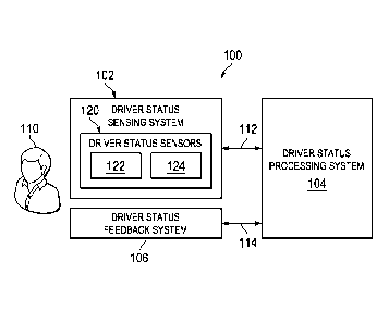
[0050] FIG. 1 is a block diagram that illustrates a driver monitoring
system ("system")
100 in accordance with one more embodiments of the present invention. As
depicted, system
100 may include driver status sensing system 102, a driver status processing
system 104, and
a driver status feedback system 106. As discussed herein system 100 may be
employed to
= collect driver status data regarding the health and/or ergonomic status
of a driver 110 when
seated in and/or driving a vehicle, process the driver status data to
assess/determine the
driver's health and/or ergonomic status, and provide feedback to the driver
regarding their
health and/or ergonomic status. For example, driver status processing system
104 may be
employed to collect (e.g., from driver status sensing system 102) driver
status data 112
regarding the health and/or ergonomic status of driver 110 when seated in
and/or driving a
vehicle, process the driver status data to assess/determine the driver's
health and/or
ergonomic status, and/or provide (e.g., to driver status feedback system 106)
driver status
feedback 114 (e.g., driver status content for presentation to the driver
regarding their current
health and/or ergonomic status and/or commands for taking automated actions to
resolve
health and/or ergonomic issues identified).
[0051] In some embodiments, the collected driver status data may be
used to assess a
physical health of the driver to determine whether the driver is experiencing
a health
condition that may be unsuitable for driving and, if the driver is
experiencing a health
condition that may be unsuitable for driving, providing corresponding
feedback. For example,
where the collected health data indicates that the driver is suffering from
fatigue, system 100
may provide the driver with an alert communicating to the driver that they
should take a
-13-
CA 02840981 2013-12-31
WO 2013/006639
PCT/US2012/045442
break from driving until they have rested for a sufficient period. Such a
system may help to
prevent vehicle accidents by alerting the driver to potential issues, such as
falling asleep
while driving, before they actually occur.
[0052] = In some embodiments, the collected driver status data may be used to
assess a
body position of the driver to determine whether their driver's body position
is ergonomically
correct and providing feedback corresponding thereto. For example, where the
driver status
data collected indicates that the driver's body position is not ergonomically
correct because
the driver's seat is too low, system 100 may provide the driver with a
suggestion to raise the
driver's seat and/or may lower the driver's seat automatically to the
suggested position. Such
a system may help to prevent physical injuries by encouraging the driver to
assume a proper
ergonomic position= that will help to prevent injuries that may otherwise
occur if the driver
were to continue to be seated in an= ergonomically unacceptable position.
[0053] In some embodiments, driver status sensing system 102 includes one
or more
driver status sensors 120 that are employed to collect the driver status data
relating the health
and/or ergonomic status of the driver (e.g., driver health data and/or driver
ergonomics data).
In some embodiments, driver status sensors 120 include one or more health
sensors 122
and/or ergonomic sensors ("body position sensors") 124. Health sensors 122 may
include
sensors that are used to collect health data indicative of biometric and/or
biomechanic health
characteristics of the driver. Ergonomic sensors 124 may include sensors that
are used to
collect ergonomic data indicative of the driver's body position when seated in
a driver's seat
of a vehicle. A sensor that is used to collect both of health data and
ergonomic data may be
referred to as an ergonomic/health sensor.
[0054] FIG. 2 illustrates an exemplary driver monitoring system 100
including status
sensing system 102 having a set of driver status sensors 120 that are disposed
throughout a
driver environment 200 of a vehicle 204 in accordance with one more
embodiments of the
present invention. Driver's environment 200 may include a region that
immediately
surrounds the driver when they are seated in driver's seat 210 of vehicle 204.
For example, in
the illustrated embodiment, driver's environment 200 includes a driver's seat
210, a
floorboard 212, pedals 214, a steering wheel 216, and a rearview mirror 218.
In some
embodiments, set of driver status sensors 120 includes any combination of one
or more of
-14-
CA 02840981 2013-12-31
WO 2013/006639
PCT/US2012/045442
heart rate sensors 219, seat sensors 220, floorboard sensors 222, pedals
sensors 224, steering
wheel sensors 226, mirror sensors 227, body position sensors 228, and/or brain
sensors 229.
[0055] Seat sensors 220 may include on or more sensors provided at driver's
seat 210 for
sensing the driver's body position when seated in driver's seat 210. For
example, seat sensors
220 may include force and/or temperature transducers for sensing the
positioning of the
driver's buttocks and upper legs on a seat portion of driver's seat 210,
sensing the positioning
of the driver's back/torso against a back portion of driver's seat 210, and/or
sensing the
positioning of the driver's head against a headrest portion of driver's seat
210.
[0056] FIG. 3 illustrates a perspective view of driver's seat 210 including
seat sensors
220 in accordance with one or more embodiments of the present invention. As
depicted,
driver's seat 210 may include a seat-bottom 230 and a seat-back 232. Seat-
bottom 230 may
include a lower portion of driver's seat 210 that is oriented substantially
horizontally for
supporting the driver's buttocks and/or upper-legs when the driver is seated
in seat 210. Seat-
bottom 230 may include an upper-seating surface 230a that contacts and
supports the driver's
buttocks and upper-legs when the driver is seated in driver's seat 210,
[0057] In some embodiments, seat-bottom 230 includes a seat sensor 220
disposed
thereon. For example, seat-bottom 230 may include a seat-bottom sensor 220a
disposed on
upper-seating surface 230a for sensing the positioning of the driver's
buttocks and upper legs
on upper-seating surface 230a of seat-bottom 230 when the driver is seated in
driver's seat
210. In some embodiments, seat-bottom sensor 220a is integrated within upper-
seating
surface 230a. For example, seat-bottom sensor 220a may be provided directly
underneath
upper-seating surface= 230a of seat-bottom 230. In some embodiments, seat-
bottom sensor
220a is integrated within a cover/pad provided on upper-seating surface 230a.
For example,
seat-bottom sensor 220a may be provided in a seat cover/pad that is disposed
on top of upper-
seating surface 230a of seat-bottom 230. In some embodiments, seat-bottom
sensor 220a =
includes a force sensor that outputs seat-bottom sensor data that is
indicative of the driver's
positioning in driver's seat 210. For example, where seat-bottom sensor 220a
includes a force
sensor, seat-bottom sensor data may be indicative of a force of the driver's
buttock and/or
upper legs exerted on upper seat surface 230a. In some embodiments, seat-
bottom sensor
220a includes a position sensor (e.g., a gyro) that outputs seat-bottom sensor
data that is
-15-
CA 02840981 2013-12-31
WO 2013/006639
PCT/US2012/045442
indicative of an orientation of the seat-bottom 230 of driver's seat 210. For
example, where
seat-bottom sensor 220a includes a gyro sensor, seat-bottom sensor data may be
indicative of
an angle of upper seat surface 230a relative to horizontal.
[0058] Seat-back 232 may include an upper portion of driver's seat 210 that
is oriented
substantially vertically for supporting the driver's back/torso/head when the
driver is seated
in seat 210. Seat-back 232 may include a back-support surface 232a that
contacts and
supports the driver's back/torso when the driver is seated in driver's seat
210.
[0059] In some embodiments, seat-back 232 includes a seat sensor 220
disposed thereon.
For example, seat-back 232 may include a seat-back sensor 220b disposed on
back-support
surface 232a for sensing the positioning of the driver's back/torso against
back-support
surface 232a when the driver is seated in driver's seat 210. In some
embodiments, seat-back
sensor 220b is integrated within back-support surface 232a. For example, seat-
back sensor
220b may be provided directly underneath back-support surface 232a of seat-
back 232. In
some embodiments, seat-back sensor 220b is integrated within a cover/pad
provided on back-
support surface 232a. For example, seat-back sensor 220b may be provided in a
seat
cover/pad that is disposed over back-support surface 232a of seat-back 232.
In= some
embodiments, seat-back sensor 220b includes a force sensor that outputs seat-
back sensor
data that is indicative of the driver's positioning in driver's seat 210. For
example, where
seat-back sensor 220b includes a force sensor, seat-back sensor data may be
indicative of a
force of the driver's back/torso exerted against back-support surface 232a. In
some
embodiments, seat-back sensor 220b includes a position sensor (e.g., a gyro)
that outputs
seat-back sensor data that is indicative of an orientation of seat-back 232 of
driver's seat 210.
For example, where seat-back sensor 220b includes a gyro sensor, seat-back
sensor data may
be indicative of an angle of back-seat surface =232a relative to vertical.
[0060] In some embodiments, seat-back 232 includes a headrest 234. Headrest
234 may
be disposed at an upper-end of seat-back 232 for supporting the driver's head
when the driver
is seated in seat 210. Headrest 234 may include a head-support surface 234a
that contacts and
supports the backside of the driver's head when the driver is seated in
driver's seat 210.
-16-
CA 02840981 2013-12-31
WO 2013/006639
PCT/US2012/045442
[0061] In some embodiments, headrest 234 includes a seat sensor 220
disposed thereon.
For example, headrest 234 may include a headrest sensor 220c disposed on head-
support
surface 234a for sensing the positioning of the driver's head against head-
support surface
234a when the driver is seated in driver's seat 210. In some embodiments,
headrest sensor
220c is integrated within head-support surface 234a. For example, headrest
sensor 220c may
be provided directly underneath head-support surface 234a of headrest 234. In
some
embodiments, headrest sensor 220c is integrated within a cover/pad provided on
head-support
surface 234a. For example, headrest sensor 220c may be provided in a headrest
cover/pad
that is disposed over head-support surface 234a of headrest 234. In some
embodiments,
headrest sensor 220c includes a force sensor that outputs headrest sensor data
that is
indicative of the driver's positioning in driver's seat 210. For example,
where headrest sensor
220c includes a force sensor, headrest sensor data may be indicative of a
force of the driver's
head exerted against head-support surface 234a. In some embodiments, headrest
sensor 220c
includes a position sensor (e.g., a gyro) that outputs headrest sensor data
that is indicative of
an orientation of head-support surface 234a of headrest 234. For example,
where headrest
sensor 220c includes a gyro sensor, headrest sensor data may be indicative of
an angle of
head-support surface 234a relative to vertical.
[0062] In some embodiments, seat 210 is adjustable to accommodate various
driving
positions. For example, seat-bottom 230 may be slid forward (e.g., toward
steering wheel
136) of backwards (e.g., away from steering wheel 216) to move the entirety of
seat 210
forward or backwards. Seat-bottom 230 may be raised or lowered to raise or
lower the
entirety of seat 210. Seat-bottom 230 may be tilted forward (e.g., rotated
clockwise in FIG. 2)
or backward (e.g., rotated counter-clockwise in FIG. 2) to tilt the entirety
of driver's seat 210
forward or backward. Seat-back 232 may be tilted forward (e.g., rotated
clockwise in FIG. 2)
or backward (e.g., rotated counter-clockwise in FIG. 2) to adjust the angle of
support for the
driver's backftorso/head. Headrest 234 may be extended upward (e.g., away from
a top of
seat-back 232) or retracted downward (e.g., toward seat-back 232) to adjust a
height for
supporting the driver's head. Head-rest 234 may be tilted forward (e.g.,
rotated clockwise in
FIG. 2) or backward (e.g., rotated counter-clockwise in FIG. 2) to adjust the
angle of support
for the driver's head.
-17-
CA 02840981 2013-12-31
WO 2013/006639
PCT/US2012/045442
[0063] In some embodiments, adjustments to seat position may be provided
manually.
For example, adjustments to the position of driver's seat 210 may include the
driver pulling
on levers and exerting manual force to slide, tilt, or otherwise adjust the
various portions of
driver's seat 210. In some embodiments, adjustments to seat position may be
provided
manually with assistance. For example, adjustments to the position of driver's
seat 210 may
include the driver pressing directional buttons that cause motors or similar
positing devices to
slide, tilt, or otherwise adjust the various portions of driver's seat 210. In
some embodiments,
adjustments to seat position may be provided automatically (e.g., with little
to no user
interaction). For example, adjustments to the position of driver's seat 210
may include motors
(or similar positing devices) that are employed to automatically slide, tilt,
or otherwise adjust
the various portions of driver's seat 210. Such automatic adjustments may be
implemented
where, for example, the driver has a preferred seating potion that is pre-
stored, and driver's
seat 210 is automatically adjusted to the preferred seating position upon
determining that the
driver is seated in driver's seat 210 and/or a selection is made to return
driver's seat 210 to
the preferred seating position (e.g., the driver or another driver selecting a
button to return the
seat in the preferred seating position). In some embodiments, automatic
adjustments may be
implemented to make adjustments to the position of the driver's seat to
correct the driver's
body position such that it is ergonomically acceptable.
[0064] FIG. 4 illustrates a perspective view of a floor region 400 of
vehicle 204 in
accordance with one or more embodiments of the present invention. In some
embodiments,
floorboard 212 includes a lower/floor surface of the vehicle where the
driver's feet are
typically located when driving. Floorboard 212 may include a substantially
horizontally
oriented upper surface 212a that is located under and adjacent pedals 214 for
supporting the
driver's feet. For example, the driver may rest a heel of their right foot on
floorboard 212
while the ball of the foot is used to engage (e.g., press down on) a gas or
brake pedal (see
FIG. 2) and/or the driver may rest a heel of their left foot on upper surface
212a of floorboard
212 while the ball of the foot is used to engage (e.g. press down on) a clutch
pedal. The driver
may rest their feet on upper surface 212a of floorboard 212 when they are not
engaging one
of pedals 214. In some embodiments, upper surface 212a of floorboard 132
includes a floor
mat disposed thereon for protecting floorboard 212 from wear and tear caused
by the driver
-18-
CA 02840981 2013-12-31
WO 2013/006639
PCT/US2012/045442
resting their feet on floorboard 212 and/or debris that may be carried into
the vehicle via the
driver's footwear.
[0065] In some embodiments, floorboard 212 includes a floorboard sensor 222
provided
thereon. For example, floorboard 212 may include floorboard sensor 222
disposed on upper
surface 212a for sensing the positioning of the driver's feet on upper surface
212a of
floorboard 212 when the driver is seated in driver's seat 210. In some
embodiments,
floorboard sensor 222 is integrated within floorboard upper surface 212a. For
example,
floorboard sensor 222 may be provided directly on or directly underneath upper
surface 212a
of floorboard 222. In some embodiments, floorboard sensor 222 is integrated
within a mat
provided on upper surface 212a. For example, floorboard sensor 222 may be
integrated with a
floor mat that is disposed on top of upper surface 212a of floorboard 212.
[0066] In some embodiments, floorboard sensor 222 includes a force sensor
that outputs
floorboard sensor data that is indicative of the positioning of the driver's
feet. For example,
where floorboard sensor 222 includes a force sensor, floorboard sensor data
may be
indicative of a force of the driver's feet (e.g., heels) exerted on upper
surface 212a. Such
floorboard sensor data may be used to determine that the driver's feet= are
contacting
floorboard 212.
[0067] In some embodiments, pedals 214 include an accelerator pedal ("gas
pedal") 214a,
a broke pedal 214b, and/or a clutch pedal 214c. The driver may depress the gas
pedal 214a
with their foot to cause the vehicle to accelerate. The driver may depress the
brake pedal
214b with their foot to cause the vehicle to decelerate (e.g., stop). The
driver may depress the
clutch pedal 214c with their foot to enable shifting of gears in a manual
transmission and/or
to regulate torque output by the vehicle. In some embodiments, gas pedal 214a,
brake pedal
214b and/or clutch pedal 214c =include a gas pedal sensor 224a, a brake pedal
sensor 224b
and/or a clutch pedal sensor 224c, respectively. The pedal sensors 224 may be
disposed on a
surface of the pedals for detecting when the driver's foot has engaged (e.g.,
is contacting) the
respective pedals.
[0068] In some embodiments, each of pedal sensors 224 includes a force
sensor that
outputs pedal sensor data that is indicative of whether the driver's feet are
engaging (e.g.,
-19-
CA 02840981 2013-12-31
WO 2013/006639
PCT/US2012/045442
contacting) pedals 214. For example, where gas pedal sensor 224a, a brake
pedal sensor 224b
and/or a clutch pedal sensor 224c each includes a force sensor, pedal sensor
data may include
gas pedal sensor data indicative of a force of the driver's foot exerted on
gas pedal 214a,
brake pedal sensor data indicative of a force of the driver's foot exerted on
brake pedal 214b,
and/or clutch pedal sensor data indicative of a force of the driver's foot
exerted on clutch
pedal 214e, respectively. Such pedal sensor data may be used to determine that
the driver's
feet are contacting pedals 214.
[0069] FIG. 5 illustrates a front view of steering wheel 216 of vehicle
204 in accordance
= with one or more embodiments of the present invention. In some
embodiments, steering
wheel 216 includes a device that can be manipulated by the driver to steer the
vehicle in a
desired direction. In= some embodiments, steering wheel 216 includes a
steering wheel sensor
226. For example, steering wheel 216 may include steering wheel sensor 226
disposed on a
body 216a of steering wheel 216 for sensing the positioning of the driver's
hands on body
216a of steering wheel 216. In some embodiments, steering wheel sensor 226 is
integrated
within body 216a. For example, steering wheel sensor 226 may be provided
directly on or
directly underneath an exterior surface of body 216a. In some embodiments,=
steering wheel
= sensor 226 is integrated within a cover provided on body 216a of steering
wheel 216. For
example, steering wheel sensor 226 may be integrated with a steering wheel
cover that is
disposed over body 216a of steering wheel 216. In some embodiments, steering
wheel sensor
226 includes one or more sensors disposed at various locations about body 216a
of steering
wheel 216 for detecting the driver's hand position on steering wheel 216. For
example, right
and left steering wheel sensors 226a and 226b may be provided at the "2
o'clock" and "10
o'clock" positions, respectively, on body 216a of steering wheel 216 such that
the positioning
of the driver's hand at the "2 o'clock" and "10 o'clock" positions can be
detected. Other
embodiments may include positioning of steering wheel =sensors 226 in any
variety of suitable
= positions for detecting the driver's hand position on body 216a of
steering wheel 216.
[0070] In some embodiments, steering wheel sensors 226 include force
sensors that output
steering wheel sensor data that is indicative of the positioning of the
driver's hands on body
216a of steering wheel 216. For example, where right and left steering wheel
sensors 226a
and 226b each include a force sensor, steering wheel sensor data may include
right steering
wheel sensor data indicative of a force of the driver's right hand exerted on
steering wheel
-20-
CA 02840981 2013-12-31
WO 2013/006639
PCT/US2012/045442
sensor 226a and/or left steering wheel sensor data indicative of a force of
the driver's left
hand exerted on steering wheel sensor 226b. Such steering wheel sensor data
may be used to
determine that the driver's hands are contacting steering wheel 216 at the "2
o'clock" and "10
o' clock" positions.
[0071] FIG. 6 illustrates a front view of rearview mirror 218 of vehicle
204 in accordance
with one or more embodiments of the present invention. In some embodiments,
rearview
mirror 218 includes a mirrored surface 218a that enables the user to see
rearward of the
vehicle. Rearview mirror 218 may be located at or near the upper/center
portion of a front
windshield of vehicle 204 such that the driver may simply gaze upward to see a
reflection of
what is located to the rear of the vehicle (e.g., other cars following the
vehicle). In some
embodiments, rearview mirror 218 includes a rearview mirror sensor 227
disposed therein.
For example, rearview mirror 218 may include a camera for sensing the driver's
body
position and/or eye position. In some embodiments, the camera includes a two-
dimensional
("2D") or three-dimensional ("3D") camera having a field of view of some or
all of the
driver's body when seated in driver's seat 210. The camera may be used to
capture images
(e.g., 2D and/or 3D video and/or still images) that can be used to determine
the driver's body
position (e.g., the position of the driver's head, torso, waist, legs, feet,
arms, hands, and/or the
like) and eye position (e.g., including the direction in which the user is
looking).
[0072] In some embodiments, rearview mirror sensor 227 outputs rearview
mirror sensor
data that is indicative of the driver's body and/or eye position. For
example,= where rearview
mirror sensor 227 includes a camera, the rearview mirror sensor data may
include image data
(e.g., 2D and/or 3D video and/or still images) that is indicative of the
driver's body position
(e.g., the position of the driver's head, torso, waist, legs, feet, arms,
hands, and/or the like)
and/or eye position (e.g., including the direction in which the user is
looking). In some
embodiments, rearview mirror sensor 227 includes a device such as the KinectTM
manufactured by Microsoft. Such a 3D camera may include a software development
kit that
provides for employing the camera as a biomechanical sensor for determining
various
biometric aspects of the employee, including body position.
[0073] In some embodiments, position sensors 228 include a set of one or
more
positioning devices (e.g., RFID sensors) that can be used to locate a relative
or absolute
-21-
CA 02840981 2013-12-31
WO 2013/006639
PCT/US2012/045442
position of various portions of the driver's body. For example, as depicted
(see FIG. 2),
position sensors 228 may include shoulder position sensors 228a located at or
near the
driver's right and left shoulder joints, hip position sensors 228b located at
or near the driver's
right and left hip joints, knee position sensors 228e located at or near the
driver's right and
left knee joints, ankle/foot position sensors 228d located at or near the
driver's right and left
ankle joints, elbow position sensors 228e located at or near the driver's
right and left elbow
joints, hand/wrist position sensors 228f located at or near the driver's right
and left wrists,
and/or head position sensors 228g located at or near the driver's right and
left ears such that a
location/position of the employee's shoulders, hip, knees, ankles/feet,
elbows, wrists/hands,
head/ears and/or the like can be determined.
[0074] In some embodiments, each of position sensors 228 output position
sensor data that
is indicative of their respective location. For example, where position
sensors 228 includes
shoulder position sensors 228a, hip position sensors 228b, knee position
sensors 228c,
ankle/foot position sensors 228d, elbow position sensors 228e, hand/wrist
position= sensors
228f, and/or head position sensors 228g, the position sensor data may include
coordinates
(e.g., 3D coordinates) indicative the location (e.g., in three-dimensional
space) of the driver's
shoulders, hip, knees, ankles/feet, elbows, wrists/hands and/or head as
provided by
corresponding ones of the sensors 228. As will be appreciated by those skilled
in the art, such
position sensor data may be used to determine locations of the corresponding
portions of the
driver's body and, thus, driver's body position. For example, shoulder
position data output by
shoulder position sensors 228a may be indicative of the locations of the
driver's shoulders
and, thus, can be used to determine the location of the driver's shoulders.
Similar position
data may be provided by each of position sensors 228 (e.g., 228a-228g) and
processed to
determine locations corresponding thereto.
[0075] In some embodiments, brain sensor 229 includes a plurality of neural
sensors for
sensing brain activity (e.g., neural activity) of the driver. A neural sensor
may include an
electrode for sensing brain activity of the driver. In some embodiments,
neural sensors may
employ electroencephalography ("EEG") to measure neuro-signal voltage
fluctuations
resulting from ionic current flows within the neurons of the brain. EEG may
refer to
recording of the brain's spontaneous electrical= activity over a short period
of time (e.g.,
twenty to forty minutes) from a plurality of neural sensors disposed on the
employee's scalp.
-22-
CA 02840981 2013-12-31
WO 2013/006639 PCT/US2012/045442
For example, a plurality of neural sensor (e.g., sixteen neural
sensors/channels) may be
disposed about the employee's scalp to detect neuro-signals (e.g., including
alpha, beta,
gamma, and delta waves) that can be used to determine the employee's brain
state, including
their emotional state (e.g., distracted, angry happy, sad, excited, etc.),
thoughts (e.g.,
cognitive thoughts, subconscious thoughts, intent, etc.), facial movements=
(e.g., facial
expressions), motor functions and/or the like. Such data can be used to
determine wither the
driver is fatigued/tired (e.g., suffering from sleep deprivation), and/or the
like.
[0076] FIG. 7 is a
perspective view of a neuro-headset 700 including a plurality of neural
sensors 702 in accordance with one or more embodiments of the present
invention. Neuro-
headset may be worn on the driver's head when seated in driver's seat 210 (see
FIG. 2).
Neuro-headset 700 may include a neuro-headset frame 704 having a plurality of
neural
sensors 702 (e.g., sixteen neural sensors 702) coupled thereto. Neuro-headset
frame 704 may
provide for positioning of the neural sensors 218 in discrete neural sensor
locations about the
driver's head. In some embodiments, one or more head positioning devices 228g
may be =
= integrated with neuro-headset 700 such that a head positioning device
228g is disposed about
the driver's head when neuro-headset 700 is being worn by the driver. For
example, head
= positioning devices 228g may be located on a portion of headset 700 to be
positioned near the
side (e.g., both ears), front and/or back of the driver's head.
[0077] In some
embodiments, brain sensors 229 output brain sensor data (e.g., neural
sensor data) that is indicative of the brain activity of the driver. For
example, where brain
sensors 229 include neural sensors 702, neural sensors 702 may output neural
sensor data
indicative of detected neuro-signals (e.g., including alpha, beta, gamma, and
delta waves) that
can be used to determine the employee's brain state/activity, including their
emotional state
(e.g., happy, sad, excited, etc.), thoughts (e.g., cognitive thoughts,
subconscious thoughts,
intent, etc.), facial movements (e.g., facial expressions), motor functions
and/or the like.
[0078] In some
embodiments, brain sensors 229 are provided in a =surface that
supports or otherwise contacts the head of driver = 110 while seated in
driver's seat 210. For
example, headrest 234 may include one or more neural sensors 702 disposed on
head-support
surface 234a (see FIGS. 2 and 3). Neural sensors 702 may contact the back of
the driver's
head while they are seated in driver's seat 210, enabling the one or more
neural sensors to
-23-
CA 02840981 2013-12-31
WO 2013/006639
PCT/US2012/045442
sense the brain activity of driver 110 when the driver is seated in driver's
seat 210. In some
embodiments, neural sensors 702 include dry electrodes that can be used to
sense neuro
signals when in contact with the driver's scalp. Such dry electrodes may
require minimal or
no skin preparation for disposing the contact of the electrode on the
employee's scalp. In
some embodiments, one or more neural sensors 702 are integrated within head-
support
surface 234a. For example, one or more neural sensors 702 may be provided
directly
underneath head-support surface 234a of headrest 234. In some embodiments, one
or more
neural sensors 702 are integrated within a cover/pad provided on head-support
surface 234a.
For example, one or more neural sensors 702 may be provided in a headrest
cover/pad that is
disposed over head-support surface 234a of headrest 234.
[0079] In some embodiments, a heart rate sensor 219 (see FIG. 2) outputs
heart rate data
112h indicative of the =driver's heart rate sensed by heart rate sensor 219
(e.g., 80 beats per
minute ("BPM")). Heart rate sensor 219 may include a heart rate monitor is
positioned about
the employee's torso (e.g., a heart rate monitor strapped about the driver's
chest).
[0080] In some embodiments, driver's environment 200 includes one or more
devices for
presenting information to the driver regarding their status. For example,
driver's environment
may include a display device 250 and/or an audio device 252 for displaying
and/or audibly
presenting information to the driver. In some embodiments, display device 250
includes a
graphical display for displaying driver status information. For example,
display device may
include a display provided in the dash of vehicle 204 (e.g., a display screen
of a radio device,
navigation device, the instrument/gauge cluster, and/or the like), a head-up
display (e.g., a
display that projects images onto a windshield 254 of vehicle 204 such that
the images are
reflected for viewing by the driver and appear as an overlay in the driver's
field of view
through the windshield), and/or the like. In some embodiments, audio device
252 includes a
speaker for presenting status information audibly to the driver. For example,
audio device
252 may include speakers of a stereo system of the vehicle, of an integrated
phone system of
the vehicle, or the like.
[0081] FIG. 8 is a block diagram that illustrates driver monitoring system
100 including
components of driver status sensing = system 102 in accordance with one or
more
embodiments of the present invention. In some embodiments, driver status
sensing system
-24-
CA 02840981 2013-12-31
WO 2013/006639
PCT/US2012/045442
102 includes a plurality of driver status sensors 120 communicatively coupled
to driver status
processing system 104 and/or driver status processing system 104 is
communicatively
coupled to driver status feedback system 106.
[0082] Driver status sensors 120 may include seat sensors 220 (e.g., seat-
bottom sensor
220a, seat-back sensor 220b, and/or headrest sensor 220c), floorboard sensors
222, pedal
sensors 224 (e.g., gas pedal sensor 224a, brake pedal sensor 224b and/or
clutch pedal sensor
224c), steering wheel sensors 226 (e.g., right steering wheel sensor 226a
and/or left steering
wheel sensor 226b), rearview mirror sensors 227, position sensors 228 (e.g.,
shoulder
position sensors 228a, hip position sensors 228b, knee position sensors 228c,
ankle/foot
position sensors 228c1, elbow position sensors 228e, hand/wrist position
sensors 228f, and/or
head position sensors 228g), and/or brain sensors 229 (e.g., neural sensors).
Driver status
processing system 104 may collect driver status data 112 from driver status
sensors 120. In
some embodiments, driver status data 112 includes sensor data collected from
the respective
sensors 120. Driver status data 112 may include seat sensor data 112a (e.g.,
including seat-
bottom sensor data, seat-back sensor data, and/or headrest sensor data)
collected from seat
sensors 220 (e.g., seat-bottom sensor 220a, seat-back sensor 220b, and/or
headrest sensor
220c), floorboard sensor data 112b collected from floorboard sensors 222,
pedal sensor data
112c (e.g., including gas pedal sensor data, brake pedal sensor data, and/or
clutch pedal
sensor data) collected from pedal sensors 224 (e.g., gas pedal sensor 224a,
brake pedal sensor
224b and/or clutch pedal sensor 224c), steering wheel sensor data 112d (e.g.,
right steering
wheel sensor data and/or left steering wheel sensor data) collected from
steering wheel
sensors 226 (e.g., right steering wheel sensor 226a and/or left steering wheel
sensor 226b),
rearview mirror sensor data 112e collected from rearview mirror sensors 227,
position sensor
data 112f (e.g., shoulder position sensor data, hip position sensor data, knee
position sensor
data, ankle/foot position sensor data, elbow position sensor data, hand/wrist
position sensor
data, and/or head position sensor data) collected from position sensors 228
(e.g., shoulder
position sensors 228a, hip position sensors 228b, knee position sensors 228c,
ankle/foot
position sensors 228d, elbow position sensors 228e, hand/wrist position
sensors 228f, and/or
head position sensors 228g), brain/neural sensor data 112g collected from
brain sensors 229
= (e.g., neural sensors 229a) and/or heart rate data 112h collected from
heart rate sensor 219.
-25-
CA 02840981 2013-12-31
WO 2013/006639
PCT/US2012/045442
[0083] In some embodiments, sensors 120 are communicatively coupled to
driver status
processing system 104 via a wired connection. For example, some or all of
sensors 120 may
include a communication cable extending between each of the respective sensors
driver status
processing system 104. In some embodiments, sensors 120 are communicatively
coupled to
driver status processing system 104 via a wireless connection. For example,
some or all of
sensors 120 may communicate with driver status processing system 104 =via a
wireless
connection such as a Bluetooth connection and/or the like. In some
embodiments, driver
status data 112 is transmitted from the respective sensors 120 to driver
status processing
system 104 via the wired or wireless connections.
[0084] FIG. 9 is a block diagram that illustrates driver monitoring system
100 including
components of driver status processing system 104 in accordance with one or
more
embodiments of the present invention. In some embodiments, driver status
processing system
104 includes a controller 900 for controlling the operational aspects of
driver status
processing system 104. For example, controller 900 may provide for collecting
driver status
data 112 from the various sensors 120 of driver status sensing system 102,
processing the
collected driver status data 112 and/or providing driver status feedback 114
to driver status
feedback system 106. In some embodiments, controller 900 includes a memory
901, a
processor 902 and an input/output (I/0) interface 904.
[0085] Memory 901 may include non-volatile memory (e.g., flash memory, ROM,
PROM, EPROM, EEPROM memory), volatile memory (e.g., random access memory
(RAM), static random access memory (SRAM), synchronous dynamic RAM (SDRAM)),
bulk storage memory (e.g., CD-ROM and/or DVD-ROM, hard-drives), or the like.
Memory
901 may include a non-transitory computer readable storage medium having
program
= instructions 906 stored thereon that are executable by a processor (e.g.,
processor 902) to
cause the functional operations (e.g., methods/routines/processes) described
herein with
regard to driver status processing system 104. Program instructions 906 may
include a driver
status processing module 908 including program instructions that are
executable by processor
902 to provide some or all of the functionality described herein with regard
to driver status
processing system 104.
-26-
CA 02840981 2013-12-31
WO 2013/006639
PCT/US2012/045442
[0086] Processor
902 may be any suitable processor capable of executing/performing
program instructions. Processor 902 may include a central processing unit
(CPU) that carries
out program instructions (e.g., of driver status processing module 908) to
perform
arithmetical, logical, and input/output operations of driver status processing
system 104,
including those described herein.
[0087] I/0
interface 904 may provide an interface for connection of one or more I/0
devices to driver status processing system 104. I/0 devices =may include
driver status sensor
system 102 (e.g., sensors 120), driver status feedback system 106 (e.g., a
display device), a
network server, and/or the like. I/0 devices may be connected to I/0 interface
904 via a wired
or wireless connection. For example, external devices 920 may be connected to
the I/0
interface via a Bluetooth wireless connection.
[0088] In some
embodiments, driver status processing system 104 is located in vehicle
= 204. For example, driver status processing system 104 may include a
computer on-board
vehicle 204. In some embodiments, driver status processing system 104 includes
a mobile
device carried by the driver that is located in vehicle 204. For example,
driver status
processing system 104 may include a laptop computer, a personal digital
assistant (PDA), a
cellular phone, a tablet computer or the like that is located within vehicle
204. In some
embodiments, driver status processing system 104 includes a remote processing
device. For
example, driver status processing system 104 may include a network server that
collects
driver status data ("status data") 112 from driver status sensing system 102
via =a
communications network (e.g., a wireless cellular network), processes status
data 112 to
determine the driver's status (e.g., health and/or ergonomic status), and
provides driver status
feedback 114 to driver status feedback system 106 via the communications
network. Such an
embodiment may off-load processing from a device in the vehicle to a
centralized server.
[0089] FIG. 10 is a
block diagram that illustrates driver monitoring system 100 including
= components of driver status feedback system 106 in accordance with one or
more
embodiments of the present invention. In some embodiments, driver status
feedback system
109 includes display device 250, audio device 252, a vehicle controller 1002,
a driver seat
controller 1004, a pedal controller 1006, a steering wheel controller 1008,
and/or a rearview
mirror controller 1010. In some embodiments, vehicle controller 1002 includes
a device that
-27-
CA 02840981 2013-12-31
WO 2013/006639
PCT/US2012/045442
can control various operational aspects of vehicle 104. For example, vehicle
controller 1002
may be capable of suspending operation of vehicle (e.g., slowing the vehicle
to a stop) in
response to receiving a command to do so (e.g., in response to receiving a
command to do so
via vehicle control feedback 114c provided by driver status processing system
104). In some
embodiments, driver seat controller 1004, pedal controller 1006, steering
wheel controller
1008, and rearview mirror controller 1010 each includes a device that can
control various
operational aspects of driver's seat 210, pedals 214, steering wheel 216, and
rearview mirror
218, respectively. For example, driver seat controller 1004 may be capable of
adjusting
position of driver's seat 210 to a given position (e.g., via controlling
positioning motors of
driver's seat 210) in response to receiving a command to do so (e.g., in
response to receiving
a command to do so via driver seat control feedback 114d provided by driver
status
processing system 104). Pedal controller 1006may be capable of adjusting
position of pedals
214 to a given position (e.g., via controlling positioning motors of pedals
210) in response to
receiving a command to do so (e.g., in response to receiving a command to do
so via driver
seat control feedback 114e provided by driver status processing system 104).
Steering wheel
controller 1008 may be capable of adjusting position of steering wheel 216 to
a given
position (e.g., via controlling positioning motors of steering wheel 216) in
response to
receiving a command to do so (e.g., in response to receiving a command to do
so via driver
seat control feedback 114f provided by driver status processing system 104).
Rearview mirror
controller 1010 may be capable of adjusting position of rearview mirror 218 to
a given
position (e.g., via controlling positioning motors of rearview mirror 218) in
response to
receiving a command to do so (e.g., in response to receiving a command to do
so via driver
= seat control feedback =114g provided by driver status processing system
104). Such
positioning may be used to adjust driver's seat 210, pedals 214, steering
wheel 216, and
rearview mirror 218 to correct the driver's body position such that it is
ergonomically
acceptable.
[0090] = In some embodiments, driver status processing system 104 collects
driver status
data ("status data") 112 via driver status sensing system 102, processes
status data 112 to
determine the driver's status (e.g., health and/or ergonomic status), and
provides driver status
feedback 114 corresponding to the driver's status to be presented (e.g.,
displayed or read
aloud) to the driver via driver status feedback system 106.
= -28-
CA 02840981 2013-12-31
WO 2013/006639
PCT/US2012/045442
[0091] Driver
status processing system 104 may use the collected driver status data 112 to
assess the driver's health and/or body position. For example, the neural
sensor data may be
used to determine whether or not the driver is suffering from fatigue or other
condition
detectable via the driver's brain activity. The seat-bottom sensor data, seat-
back sensor data,
headrest sensor data, floorboard sensor data, pedal sensor data, steering
wheel sensor data,
rearview mirror sensor data, and/or position sensor data may be used to
determine whether or
not the driver's body position in driver's seat 210 is ergonomically
correct/acceptable. In
some embodiments, the brain/neural sensor data may also be used to assess the
driver's body
position. For example, the= brain/neural sensor data can be used to determine
that the driver is
uncomfortable in their current body position. In such an embodiment, system
100 may
provide for adjusting the driver's body position to increase the driver's
comfort level.
= [0092]
Driver status feedback 114 may include content that can be presented to the
driver
to inform them of their current and/or predicted health and/or ergonomic
status. For example,
where the collected driver status data 112 indicates that the driver is
suffering from fatigue,
driver status processing system 104 may generate a health alert to inform the
driver of the
fatigue condition and suggests that the driver take a break from driving until
they have rested
for a sufficient period. As a further example, where the collected driver
status data 112
indicates that the driver's body position is not ergonomically correct because
the driver's seat
is too low, driver status processing system 104 may generate an ergonomics
alert to inform
the driver of the seat being too low condition and provide a suggestion that
the driver raise
driver's seat 210. Such alerts (e.g., health and/or ergonomic alerts) may be
forwarded to
driver status feedback system 106 for presentation to the driver. For example,
driver status
= feedback system 106 may read the alert audibly to the driver via speaker
252 located in the
vehicle and/or present the alert visually to driver via display device 250
located in the
vehicle. Such alerts may help to prevent injury by encouraging the driver to
take corrective
action prior to the driver actually incurring a physical injury and/or being
involved in an
accident that may be attributed to the identified issue.
[0093] In some
embodiments, driver status feedback 114 may provide for implementing
an action. For example, where the collected driver status data 112 indicates
that the driver is
suffering from a critical condition (e.g., has fallen asleep, is suffering a
stroke or heart attack,
and/or the like), driver status processing system 104 may generate a command
to inhibit
-29-
CA 02840981 2013-12-31
WO 2013/006639
PCT/US2012/045442
operation of the vehicle (e.g., slow the vehicle to a stop). As a further
example, where the
collected driver status data 112 indicates that the driver's body position is
not ergonomically
correct because the driver's seat is too low, driver status processing system
104 may generate
a command raise the driver's seat automatically to a position that corrects
the driver's body
position such that it is ergonomically acceptable. Such commands may be
carried out via the
driver status feedback system 106. For example, in response to such commands,
vehicle
controller 1002 of driver status feedback system 106 may communicate with a
control system
of the vehicle to bring the vehicle to a stop and/or communicate with a driver
seat controller
1004 to automatically adjust the driver's seat 210 to the suggested position.
Such actions may
help to prevent injury by taking corrective action prior to the driver
actually incurring a
= physical injury and/or being involved in an accident that may be
attributed to the identified
issue.
[0094] FIG. 11 is a flowchart that illustrates a method 1100 of monitoring
the status of a
driver of a vehicle in accordance with one or more embodiments of the present
invention.
Method 1100 may include collecting driver status data, as depicted at block
1102. In some
embodiments, collecting driver status data includes driver status processing
system 104
collecting driver status data 112 from driver status sensing system 102. For
example,
controller 900 of driver status processing system 104 may collect/receive
driver status data
112 via sensors 120 of driver status sensing system 102. Driver status data
112 may include
seat sensor data 112a (e.g., including seat-bottom sensor data, seat-back
sensor data, and/or
headrest sensor data) collected from seat sensors 220 (e.g., seat-bottom
sensor 220a, seat-
back sensor 220b, and/or headrest sensor 220c), floorboard sensor data 112b
collected from
floorboard sensors 222, pedal sensor data 112c (e.g., including gas pedal
sensor data, brake
pedal sensor data, and/or clutch pedal sensor data) collected from pedal
sensors 224 (e.g., gas
pedal sensor 224a, brake pedal sensor 224b and/or clutch pedal sensor 224c),
steering wheel
sensor data 112d (e.g., right steering wheel sensor data and/or left steering
wheel sensor data)
collected from steering wheel sensors 226 (e.g., right steering wheel sensor
226a and/or left
steering wheel sensor 226b), rearview mirror sensor data 112e collected from
rearview mirror
sensors 227, position sensor data 112f (e.g., shoulder position sensor data,
hip position sensor
data, knee position sensor data, ankle/foot position sensor data, elbow
position sensor data,
hand/wrist position sensor data, and/or head position =sensor data) collected
from position
-30-
CA 02840981 2013-12-31
WO 2013/006639
PCT/US2012/045442
sensors 228 (e.g., shoulder position sensors 228a, hip position sensors 228b,
knee position
sensors 228c, ankle/foot position sensors 228d, elbow position sensors 228e,
hand/wrist
position sensors 228f, and/or head position sensors 228g), brain/neural sensor
data 112g
collected from brain sensors 229 (e.g., neural sensors 229a) and/or heart rate
data 112h
collected from heart rate sensor 219. In some embodiments, driver status data
112 is
stored/buffer for processing. For example, controller 900 of driver status
processing system
104 may store/buffer the received/collected driver status data 112 in memory
901. In some
embodiments, driver status data 112 may be logged for a given period. For
example,
controller 900 of driver status processing system 104 may log historical
driver status data 112
for a preceding time period (e.g., the preceding second, ten seconds, thirty
seconds, one-
minute, ten-minutes, thirty-minutes, one-hour, twelve hours, twenty four
hours, etc.) in
memory 901. Such logged data may be used to assess characteristics that are
dependent on
historical data. For example, a log of brain activity over a given period may
be used to track
patterns in the driver's brain activity that are indicative of fatigue and/or
develop baselines
that can be used to identify abnormalities in brain activity that are
indicative of a stroke or
heart attack.
[0095] In some embodiments, collecting driver status data includes
collecting driver
status data based on schedule. For example, where a driver status collection
schedule requires
that driver status data 112 be acquired at a given time (e.g., ten seconds
after the vehicle is
started), controller 900 of driver status processing system 104 may
collect/receive driver
status data 112 (e.g., a single set of measurements) collected via sensors 120
of driver status
sensing system 102 at the given time. Where a driver status collection
schedule requires that
driver status data 112 be acquired at a regular interval (e.g., once per
minute), controller 900
of driver status processing system 104 may collect/receive driver status data
112 (e.g., a
single set of measurements) collected via sensors 120 of driver status sensing
system 102 at
each of the intervals. Where a driver status collection schedule requires that
driver status data
112 be acquired continuously (e.g., as fast as can reasonably be acquired by
driver status
sensing system 102 and/or driver status processing system 104) or
substantially continuously
(e.g., once per second), controller 900 of driver status processing system 104
may
collect/receive driver status data 112 (e.g., a single set of measurements)
collected via sensors
120 of driver status sensing system 102 continuously or at least substantially
continuously.
-31-
CA 02840981 2013-12-31
WO 2013/006639
PCT/US2012/045442
Such rapid collection of driver status data 112 may enable system 100 to
provide the driver
with real-time feedback regarding their health and/or ergonomic status when
they are driving
the vehicle.
[0096] In some embodiments, collecting driver status data includes
collecting driver
status data at a given time and/or during a given period. In some embodiments,
a driver status
collection schedule may require that driver status data 112 be acquired while
the vehicle is
being operated (e.g., the ignition is turned on). For example, driver status
data 112 may be
collected continuously and/or at regular intervals from the time the driver
insert the key into
the ignition or turns-on the ignition until the driver turns-off the ignition
or removes the key
from the ignition. In some embodiments, a driver status collection schedule
may require that
driver status data 112 be acquired during the time when the driver is located
in driver's seat
210. For example, driver status data 112 may be continually acquired from seat-
bottom
sensor 220a and may be processed (e.g., by controller 900) to determine when
the driver is
seated in driver's seat 210. When it is determined that the driver is seated
in driver's seat 210
= (e.g. based on force detected by seat-bottom sensor 220a that exceeds a
threshold force), the
collection of driver status data 112 may be triggered such that driver status
data 112 is
acquired when the driver is located in driver's seat 210. In some embodiments,
the collection
of driver status data 112 may terminate upon detecting that the driver is no
longer seated in
the driver's seat. Such embodiments may provide for collection driver status
data, processing
or driver status data and/or feedback of driver status data when the driver is
driving the
vehicle.
[0097] Method 1100 may include processing the driver status data collected
to determine
a driver status, as depicted at block 1104. In some embodiments, processing
the driver status
data collected to determine a driver status includes processing driver status
data 112 to
determine a health status of the driver and/or an ergonomic status of the
driver. For example,
controller 900 of driver status processing system 104 may process the
collected health data to
= determine an emotional state of the driver, to determine health
characteristics of the driver, to
determine whether or not the driver is experiencing a health issue (e.g., that
may require a
health alert) and/or to determine whether or not the driver is experiencing a
health crisis (e.g.,
a health issue that may require a an action to relive the driver from control
of the vehicle). As
a further example, controller 900 of driver status processing system 104 may
process the
= -32-
CA 02840981 2013-12-31
WO 2013/006639
PCT/US2012/045442
collected ergonomic data to determine a body position of the driver, to
determine whether the
body position of the driver is ergonomically correct/acceptable, to identify
adjustments that
can be made to correct the driver's body position and/or to identify actions
that can be taken
to provide the adjustment identified.
[0098] Method 1100 may include providing driver status feedback
corresponding to the
determined driver status, as depicted at block 1106. In some embodiments,
providing driver
status feedback corresponding to the determined driver status includes
providing content for
presentation to the driver and/or causing actions to address/correct the
current driver status.
For example, where it is determined that the driver is in good health (e.g.,
the driver is not
experiencing a health issue/crisis), controller 900 may transmit, to driver
status feedback
system 106, feedback data 114 (e.g., 114a and/or 114b) including health status
content
indicative of the driver being in good health (e.g., a green health status
icon and/or a message
stating "You are in good health"). Such content may be displayed to the driver
via display
250 and/or read audibly to the driver via speaker 252.
[00991 Where it is determined that the driver is experiencing a health
issue (e.g., the
driver is suffering from fatigue), controller 900 may transmit, to driver
status feedback
system 106, feedback data 114 (e.g., 114a and/or 114b) including health alert
content
indicative of the health issue (e.g., a flashing/blinking red health status
icon and/or a message
stating "You are fatigued. When possible, please stop operating the vehicle
and do not drive
until you have rested adequately"). Such content may be displayed to the
driver via display
250 and/or read audibly to the driver via speaker 252. Such alerts may help to
prevent injury
by encouraging the driver to take corrective action prior to the driver
actually incurring a
physical injury and/or being involved in an accident that may be attributed to
the identified
issue.
[00100] Where it is determined that the driver is experiencing a health crisis
(e.g., the
driver is experiencing a stroke), controller 900 may transmit, to driver
status feedback system
106, feedback data 114 (e.g., 114c) including a command to bring the vehicle
to a stop,
and/or controller 900 may transmit, to driver status feedback system 106,
feedback data 114
(e.g., 114a and/or 114b) including a health alert indicative of the health
crisis (e.g., a
flashing/blinking red health status icon and/or a message stating "You are
experiencing a
-33-
CA 02840981 2013-12-31
WO 2013/006639
PCT/US2012/045442
stroke. Please reduce your speed immediately and stop operating the vehicle").
Such content
may be displayed to the driver via display 250 and/or read audibly to the
driver via speaker
252. In response to the command to bring the vehicle to a stop, vehicle
controller 1002 may
be employed to reduce the speed of the vehicle and/or slow the vehicle to a
stop. Such action
may help to reduce the likelihood of accidents that may otherwise occur when
the driver that
is experiencing a health crisis that renders them unable to adequately control
vehicle 204.
[00101] Where it is determined that the= driver has good ergonomic positioning
(e.g., the
driver has good body position), controller 900 may transmit, to driver status
feedback system
106, feedback data 114 (e.g., 114a and/or 114b) including ergonomic status
content indicative
of the driver having good body position (e.g., a green ergonomic status icon
and/or a message
stating "Your body position is good"). Such content may be displayed to =the
driver via
display 250 and/or read audibly to the driver via speaker 252.
[00102] Where it is determined that the driver has poor ergonomic positioning
(e.g., the
driver has poor body position that is not ergonomically correct/acceptable),
controller 900
may transmit, to driver status feedback system 106, feedback data 114 (e.g.,
114a and/or
114b) including content including an ergonomic alert indicative of the need
for the driver to
adjust body position (e.g., a flashing/blinking red ergonomic status icon
and/or a message
stating "Your body position is poor. Please move the driver's seat upward").
Such content
may be displayed to the driver via display 250 and/or read audibly to the
driver via speaker
252. In some embodiments, controller 900 may also transmit feedback data 114
(e.g., 114d,
114e, 114f, and/or 114g) including commands to automatically move the driver's
seat (e.g.,
upward) the pedals, the steering wheel and/or the rearview mirror to correct
the driver's body
position. In response to a command to move the driver's seat upward, for
example, driver seat
= controller 1004 may be employed to actuate motors or similar devices of
driver's seat 210 to
adjust driver's seat 210 to a position such that= the driver's body position
is ergonomically
correct. Such action may enable automatic adjustment of driver's seat 210
and/or portions of
driver's environment 200 with little to no interaction by the driver.
[00103] FIG. 12 is a flowchart that illustrates a method of method 1200 of
monitoring the
status of a driver and providing corresponding alerts in accordance with one
or more
embodiments of the present invention. As discussed herein, method= 1200 may
provide for
-34-
CA 02840981 2013-12-31
WO 2013/006639
PCT/US2012/045442
monitoring of the driver status while he/she is seated in the driver's seat of
a vehicle and may
provide feedback (e.g., in the form of information and/or actions) in the
event an alert
condition (e.g., a health alert or an ergonomic alert condition) is
identified.
[00104] Method 1200 may include monitoring a driver's seat of a vehicle, as
depicted at
block 1202. Monitoring a driver's seat of a vehicle may include monitoring a
driver's seat of
a vehicle to determine if a driver is seated therein. In some embodiments,
monitoring a
driver's seat of a vehicle to determine if a driver is seated therein may
include monitoring
data collected from one or more driver status sensors 120 of driver status
sensing system 102
to determine whether or not a driver is seated in driver's seat 210. For
example, controller
900 may continually acquire and process seat-bottom sensor data from seat-
bottom sensor
220a to determine whether a driver is seated in driver's seat 210. In some
embodiments, it is
determined that a person is seated in driver's seat 210 when the force sensed
by seat-bottom
sensor 220a exceeds a force threshold. For example, controller 900 may
determine that driver
110 is seated in driver's seat 210 upon seat-bottom sensor data being
indicative of a force that
exceeds 22kg (50 lbs). It will be appreciated by those skilled in the art that
a similar
determination may be made based on forces sensed by any of sensors 120 of
system 100.
[00105] As a further example, controller 900 may continually acquire and
process
rearview mirror data from rearview mirror sensor 227 to determine whether a
driver is seated
in driver's seat 210. In some embodiments, it is determined that a person
(e.g., driver 110) is
seated in driver's seat 210 when image data acquired by rearview mirror sensor
indicates that
a person is located in driver's seat 210. For example, controller 900 may
determine that
driver 110 is seated in driver's seat 210 upon rearview mirror sensor data
including an image
indicative of a person being located in driver seat 210.
[00106] Where it is determined that a driver is not seated in the driver seat
of the vehicle,
method 1200 may include continuing to monitor the driver seat of the vehicle,
as depicted at
block 1204. Where it is determined that a driver is seated in the driver seat
of the vehicle,
method 1200 may include proceed to collecting driver status data, as depicted
at block 1206.
= [00107] Collecting driver status data may be the same or similar to that
described with
= regard to block 1102 of method 1100 (see FIG. 11). For example,
controller 900 of driver
-35-
CA 02840981 2013-12-31
WO 2013/006639
PCT/US2012/045442
status processing system 104 may collect/receive/store/log driver status data
112 collected via
sensors 120 of driver status sensing system 102. Driver status data = 112 may
include seat
sensor data 112a (e.g., including seat-bottom sensor data, seat-back sensor
data, and/or
headrest sensor data) collected from seat sensors 220 (e.g., seat-bottom
sensor 220a, seat-
back sensor 220b, and/or headrest sensor 220c), floorboard sensor data 112b
collected from
floorboard sensors 222, pedal sensor data 112c (e.g., including gas pedal
sensor data, brake
pedal sensor data, and/or clutch pedal sensor data) collected from pedal
sensors 224 (e.g., gas
pedal sensor 224a, brake pedal sensor 224b and/or clutch pedal sensor 224c),
steering wheel
sensor data 112d (e.g., right steering wheel sensor data and/or left steering
wheel sensor data)
collected from steering wheel sensors 226 (e.g., right steering wheel sensor
226a and/or left
steering wheel sensor 226b), rearview mirror sensor data 112e collected from
rearview mirror
sensors 227, position sensor data 112f (e.g., shoulder position sensor data,
hip position sensor
data, knee position sensor data, ankle/foot position sensor data, elbow
position sensor data,
hand/wrist position sensor data, and/or head position sensor data) collected
from position
sensors 228 (e.g., shoulder position sensors 228a, hip position sensors 228b,
knee position
sensors 228c, ankle/foot position sensors 228d, elbow position sensors 228e,
hand/wrist
position sensors 228f, and/or head position sensors 228g), brain/neural sensor
data 112g
collected from brain sensors 229 (e.g., neural sensors 229a) and/or heart rate
data 112h
collected from heart rate sensor 219.
[00108] Method 1200 may include processing the driver status data collected to
determine
a driver status, as depicted at block 1202. Processing the status data
collected to determine a
driver status may be the same or similar to that described above with regard
to block 1104 of
method 1100 (see FIG. 11). In some embodiments, processing the driver status
data collected
to assess a driver status includes processing driver status data 112 to
determine a health status
of the driver and/or an ergonomic status of the driver. For example,
controller 900 of driver
status processing system 104 may process the collected health data to
determine a health
status including an emotional state, health characteristics/conditions, health
issues, health
crises, and/or the like for the driver. As a further example, controller 900
of driver status
processing system 104 may process the collected ergonomic data to determine an
ergonomic
status including a body position of the driver, differences between an
ergonomically correct=
body position and the driver's current body position, adjustments that can be
made to correct
-36-
CA 02840981 2013-12-31
WO 2013/006639
PCT/US2012/045442
the driver's body position and/or adjustment in the driver's environment that
can be made to
provide for the identified adjustments in body position.
[00109] In some embodiments, an emotional state for the driver is determined
based at=
least in part on brain/neural data 112g received from brain sensors 229. For
example,
controller 900 of driver status processing system 104 may process neuro-
signals (e.g.,
including alpha, beta, gamma, and delta waves) of brain/neural data 112g to
determine the
driver's current emotional state, including, for example, whether =the driver
is happy, sad,
excited, angry, distracted, etc.). In some embodiments, the emotional state is
determined
based on other forms of brain activity. For example, controller 900 of driver
status processing
system 104 may process neuro-signals to determine the driver's thoughts (e.g.,
cognitive
thoughts, subconscious thoughts, intent, etc.) and the thoughts may be used to
determine that
the driver is distracted (e.g., thinking about things other than driving),
angry (e.g., having
negative thoughts other driver's), and/or the like.
[00110] In some embodiments, health conditions for the driver are determined
based on
driver status data 112 received from one or more of sensors 120. For example,
controller 900
of driver status processing system 104 may process driver status data 112 to
determine
whether the driver is distracted, fatigued, has fallen asleep, is suffering a
stroke/heart-attack,
and/or the like. In some embodiments, a determination of whether the driver is
fatigued is
based on the driver's brain activity. For example, controller 900 may
determine that the
= driver is suffering from fatigue based on brain/neural data 112g
indicative of an abnormally
low amount of brain activity. In some embodiments, the driver's fatigue is
based on the
driver's eye movement. For example, controller 900 may determine that the
driver is
suffering from fatigue based on rearview mirror data 112e including images
that indicative of
an abnormally low amount of eye movement (e.g., the driver is focusing on one
location
which is indicative of the driver experiencing tunnel vision).
[00111] In some embodiments, a determination of whether the driver has fallen
asleep is
based on the driver's brain activity. For example, controller 900 may
determine that the
driver is asleep based on brain/neural data 112g indicative of a sleep state.
In some
embodiments, the driver's fatigue is based on the driver's eye position. For
example,
= controller 900 may determine that the driver is suffering from fatigue
based on rearview
-37-
CA 02840981 2013-12-31
WO 2013/006639
PCT/US2012/045442
mirror data 112e including images that indicative of the driver's eye being
closed for at least=
a threshold period of time (e.g., greater than three seconds).
[00112] In some embodiments, a determination of whether the driver is
suffering a stroke
is based on the driver's brain activity. For example, controller 900 may
determine that the
driver is suffering a stroke based on brain/neural data 112g indicative of a
rapid loss of brain
function in a manner that= is consistent with a stroke caused by a disturbance
in blood flow to
the brain.
[00113] In some embodiments, a determination of whether the driver is
suffering a heart-
attack is based on the driver's heart rate. For example, controller 900 may
determine that the
driver is suffering a heart attack based on heart rate data 112 indicative of
the driver's heart
rate fluctuating abnormally in a manner consistent with a heart attack.
[00114] In some embodiments, the ergonomic status for the driver is determined
based on
driver status data 112 received from one or more of sensors 120. For example,
controller 900
of driver status processing system 104 may process driver status data 112 to
determine
whether the driver is situated in an ergonomically correct/acceptable body
position.
[00115] FIG. 13 is a flowchart that illustrates a method 1300 for determining
an ergonomic
status for the driver in accordance with one or more embodiments of the
present invention.
Method 1300 may include determining a driver body position 1301, as depicted
at block
1302. In some embodiments, determining a driver body position includes
determining the
current body position of the driver based on current driver status data 112.
For example,
controller 900 of driver status processing system 104 may process driver
status data 112 to
determine the driver's current body position. In some embodiments, the
driver's current body
position is based on seat sensor data 112a (e.g., including seat-bottom sensor
data, seat-back
sensor data, and/or headrest sensor data), floorboard sensor data 112b, pedal
sensor data 112c
(e.g., including gas pedal sensor data, brake pedal sensor data, and/or clutch
pedal sensor
data), steering wheel sensor data 112d (e.g., right steering wheel sensor data
and/or left
steering wheel sensor data), rearview mirror sensor data 112e collected from
rearview mirror
sensors 227, position sensor data 112f (e.g., shoulder position sensor data,
hip position sensor
data, knee position sensor data, ankle/foot position sensor data, elbow
position sensor data,
-38-
CA 02840981 2013-12-31
WO 2013/006639
PCT/US2012/045442
hand/wrist position sensor data, and/or head position sensor data), and/or
brain/neural sensor
data 112g collected from brain sensors 229.
[00116] In some embodiments, seat sensor data 112a is used to assess how the
driver's
buttocks/upper-legs, back and head are supported by corresponding portions of
driver's seat
210a. For example, controller 900 of driver status processing system 104 may
process seat-
bottom sensor data, seat-back data and/or headrest sensor data to determine a
supporting
force, if any, exerted by upper-seat surface 230a, back-seat surface 232a,
and/or headrest-
support surface 234a, respectively.
[00117] In some embodiments, floorboard sensor data 112b is used to assess how
the
driver's feet are supported by floorboard 212. For example, controller 900 of
driver status
processing system 104 may process floorboard sensor data 112b to determine a
supporting
force, if any, exerted by floorboard surface 212.
[00118] In some embodiments, pedal sensor data 112c is used to assess whether
the
driver's feet reach pedals 214. For example, controller 900 of driver status
processing system
104 may process gas-pedal sensor data, break-pedal sensor data and/or clutch
pedal sensor
data to determine a contact force, if any, exerted by the driver's feet on gas
pedal 214a, brake
pedal 214b, and/or clutch pedal 214c, respectively.
[00119] In some embodiments, steering wheel sensor data 112d is used to assess
where the
driver's hands are located on steering wheel 216. For example, controller 900
of driver status
processing system 104 may process right steering wheel sensor data and/or left
steering
wheel sensor data to determine a contact force, if any, exerted by the
driver's hands at the
location of right steering wheel sensor 226a and/or left steering wheel sensor
226b,
respectively.
[00120] In some embodiments, rearview mirror sensor data 112e is used to
assess various
aspects of the driver's body position. For example, controller 900 of driver
status processing
system 104 may process rearview sensor data 112e (e.g., including 2D or 3D
still or video
images of the driver) to determine the driver's eye position relative to the
rear view mirror,
shoulder position, hip/waist position, leg position (e.g., including knee
position and
-39-
CA 02840981 2013-12-31
WO 2013/006639
PCT/US2012/045442
ankle/foot position), arm position (e.g., including elbow position and
hand/wrist position),
and/or head position.
[00121] In some embodiments, position sensor data 112f is used to assess
various aspects
of the driver's body position. For example, controller 900 of driver status
processing system
104 may process position sensor data 112f (e.g., 3D coordinates) to determine
the driver's
shoulder position, hip/waist position, leg position (e.g., including knee
position and
ankle/foot position), arm position (e.g., including elbow position and
hand/wrist position),
and/or head position.
[00122] In some embodiments, brain/neural sensor data 112g is used to assess
the driver's
comfort level with their body position. For example, controller 900 of driver
status
processing system 104 may process brain/neural sensor data 112g to determine
the driver's
level of discomfort based on the sensed brain/neural activity.
[00123] Method 1300 may include identifying a target ergonomic body position
1303, as
depicted at block 1304. A target ergonomic body position may include a desired
body
position for driver while seated in a driver's seat of a vehicle. Target
ergonomic body
= position 1303 may define desired characteristics for a driver's eye
position, contact with the
bottom back and headrest of the driver's seat, weight distribution within the
driver's seat, foot
contact with the floorboard, foot contact= with pedals, the driver's shoulder
position, hip/waist
position, leg position (e.g., including knee position and ankle/foot
position), arm position
(e.g., including elbow position and handlwrist position), head position and/or
the like. Target
ergonomic body position 1303 may define acceptable ranges for body position
characteristics.
[00124] FIG. 14 is illustrates characteristics of a target ergonomic body
position for a
driver ("ergonomic body position") 1303 in accordance with one or more
embodiments of the
present invention. Target ergonomic body position 1303 may include some or all
of the
following ergonomic body position characteristics: the back of the driver's
head contacting
headrest 234 (see headrest contact point 1402); the driver's back contacting
seat-back 232
(see seat-back= contact point 1404); the driver's buttock/upper legs
contacting seat-bottom 230
(see leg contact point 1406); the driver's feet are contacting floorboard 212
(see floorboard
= -40-
CA 02840981 2013-12-31
WO 2013/006639
PCT/US2012/045442
contact point 1408); the driver's feet contacting at least one of pedals 214
(see pedal contact
point 1410); the driver's hands contacting steering wheel 214 at the "2
o'clock" and "10
o'clock" positions (see steering wheel contact points 1412a and 1412b); the
driver's eye level
and rearview mirror angle being such that the driver does not have to raise or
lower their head
to see rearward of the vehicle using rearview mirror 218 (see eye direction
1414); the driver's
head (see head location 1416) located vertically over the driver's shoulder
(see shoulder
location 1418); the driver's back being angled 30 from vertical (see back
angle 1420
between vertical axis 1422 and torso line 1424 extending from shoulder
location 1418 to hip
location 1426); the angle between the driver's torso and upper leg being 105
(see upper leg
angle 1428 between torso line 1424 and upper leg line 1430 extending from hip
location 1426
to knee location 1432); the angle between the driver's upper leg and lower leg
being 135'
(see knee angle 1434 between upper leg line 1430 and lower leg line 1436
extending from
knee location 1430 to ankle/foot location 1438); the angle between the
driver's torso line
1424 and arm being 45 (see shoulder angle 1440 between torso line 1424 and
upper arm line
1442 extending from shoulder= location 1418 to elbow location 1444); the angle
between the
= driver's upper arm and lower arm being 140 (see elbow angle 1446 between
upper arm line
1442 and lower arm line 1448 extending from elbow location 1444 to wrist/hand
location
1450; an 80/20 force distribution ratio between a force of driver's
buttock/upper legs
supported by seat-bottom 230 (see leg contact point 1406) and the force of
driver's back
supported by seat-back 232 (see seat-back contact point 1404) (a "seat
bottom/back force
ratio"); and/or the like.
[001251 In some embodiments, ergonomic body position characteristics may
include
acceptable range for one or more of the characteristics. For example, body
position 1303 may
include some or all of the following ergonomic body position acceptable ranges
for the
characteristics: back angle 1420 between 25 and 35'; upper leg angle 1428
between 100 and
110"; knee angle 1434 between 130 and 140'; shoulder angle 1440 between 40
and 50';
elbow angle 1446 between 135 and 145'; seat bottom/back force ratio between
70/30 and
90/10; and/or the like. In such an embodiment, the driver may be considered to
have
good/acceptable body position if they meet the ergonomic body position
characteristics (e.g.,
the body position characteristics fall within the acceptable ranges of target
ergonomic body
position 1303).
-41-
CA 02840981 2013-12-31
WO 2013/006639
PCT/US2012/045442
[001261 In some embodiments, target ergonomic body position 1303 is stored in
memory
901. Target ergonomic body position 1303 may include ergonomic body position
data
including some or all of the ergonomic= body position characteristics of
target ergonomic
body position= 1303. In some embodiments, identifying a target ergonomic body
position
includes identifying one or more characteristics of an ergonomic body
position. For example,
identifying a target ergonomic body position may include controller 900
retrieving and/or
otherwise accessing/referencing the ergonomic body position
characteristics/data stored in
memory 901,
[00127] In some embodiment, determining a driver body position includes
determining
characteristic of the driver's= body position that correspond to
characteristics of target
ergonomic body position 1303. For example, controller 900 of driver status
processing
system 104 may process the most recent driver status data 112 received to
determine some or
all of the following: whether the back of the driver's head is contacting
headrest 234; whether
the driver's back is contacting seat-back 232; whether the driver's
buttock/upper legs are
contacting seat-bottom 230; whether the driver's feet are contacting
floorboard 212; whether
the driver's feet are contacting at least one of pedals 214; whether the
driver's hands are
contacting steering wheel 214 at the "2 o'clock" and "10 o'clock" positions;
whether the
driver's eye level and rearview mirror angle is such that the driver does not
have to raise or
lower their head to see rearward of the vehicle using rearview mirror 218;
whether the
driver's back angle 1420 is between 25 and= 35 ; whether the driver's upper
leg angle 1428 is
between 1000 and I10 ; whether the driver's knee angle 1434 is between 130
and 140 ;
whether the driver's shoulder angle 1440 is between 40 and 50 ; whether the
driver's elbow
angle 1446 between 135 and 145 ; whether the driver's seat bottom/back force
ratio is
between 70/30 and 90/10; and/or the like.
[00128] In some embodiments, controller 900 of driver status processing system
104 may
determine that the back of the driver's head is contacting headrest 234 where
it is determined
that a supporting force of at least a threshold force value (e.g., lkg
(21bs.)) is exerted by
headrest-support surface 234a. In= some embodiments, controller 900 of driver
status
processing system 104 may determine that the back of the driver's head is not
contacting
headrest 234 where it is determined that a supporting force of at least the
threshold force
= value is not exerted by headrest-support surface 234a.
-42-
CA 02840981 2013-12-31
WO 2013/006639
PCT/US2012/045442
[00129] In some embodiments, controller 900 of driver status processing system
104 may
determine that the driver's back is contacting seat-back 232 where it is
determined that a
supporting force of at least a threshold force value (e.g., 10kg (221bs.)) is
exerted by back-
seat surface 232a. In some embodiments, controller 900 of driver status
processing system
104 may determine that the driver's back is not contacting seat-back 232 where
it is
determined that a supporting force of at least the= threshold force value is
not exerted by back-
seat surface 232a.
[00130] In some embodiments, controller 900 of driver status processing system
104 may
determine that the driver's buttock/upper legs are contacting seat-bottom 230
where it is
determined that a supporting force of at least a threshold force value (e.g.,
50kg (1101bs.)) is
exerted by =back-seat surface 232a. In some embodiments, controller 900 of
driver status
processing system 104 may determine that the driver's buttock/upper legs are
not contacting
seat-bottom 230 where it is determined that a supporting force of at least the
threshold force
value is not exerted by back-seat surface 232a.
[00131] In some embodiments, controller 900 of driver status processing system
104 may
determine that the driver's feet are contacting floorboard 212 where it is
determined that a
supporting force of at least a threshold force value (e.g., lkg (21bs.)) is
exerted by floorboard
surface 212. In some embodiments, controller 900 of driver status processing
system 104
may determine that the driver's feet are not contacting floorboard 212 where
it is determined
that a supporting force of at least the threshold force value is not exerted =
by floorboard
surface 212.
[00132] In some embodiments, controller 900 of driver status processing system
104 may
determine that the driver's feet are contacting (e.g., reaching) at least one
of pedals 214 where
= it is determined that a force of at least a threshold force value (e.g.,
lkg (21bs.)) is exerted on
gas pedal 214a, brake pedal 214b, and/or clutch pedal 214c. In some
embodiments, controller
900 of driver status processing system 104 may determine that the driver's
feet are not
contacting at least one of pedals 214 where it is determined that a force of a
least the
threshold force value is not exerted on gas pedal 214a, brake pedal 214b,
and/or clutch pedal
214c.
-43-
CA 02840981 2013-12-31
WO 2013/006639
PCT/US2012/045442
[00133] In some embodiments, controller 900 of driver status processing system
104 may
determine that the driver's hands are contacting steering wheel 214 at the "2
o'clock" and "10
o'clock" positions where it is determined that a force of at least a threshold
force value (e.g.,
0.5kg (11bs.)) is exerted at the location of right steering wheel sensor 226a
and left steering
wheel sensor 226b. In some embodiments, controller 900 of driver status
processing system
104 may determine that the driver's hands are not contacting steering wheel
214 at the "2
o'clock" and "10 o'clock" positions where it is determined that a force of at
least a threshold
force value is not exerted at the location of right steering wheel sensor 226a
or left steering
wheel sensor 226b.
[00134] In some embodiments, controller 900 of driver status processing system
104 may
determine that the driver's eye level and rearview mirror angle are sufficient
such that the
driver does not have to raise or lower their head to see rearward of the
vehicle using rearview
= mirror 218 where the driver's eye and the rear of the vehicle are in
field of view of the
camera. In some embodiments, controller 900 of driver status processing system
104 may
= determine that the driver's eye level and rearview mirror angle are not
sufficient where the
driver's eyes or the rear of the vehicle are in the field of view of the
camera.
[00135] In some embodiments, controller 900 of driver status processing system
104 may
determine the positions and angles of the various locations based on position
sensor data
and/or rearview mirror sensor data. For example, controller 900 may use
coordinates for hip
position 1426 (e.g., provided by hip position sensor 229b), knee position 1432
(e.g., provided
by knee position sensor 229c) and/or foot/ankle position 1438 (e.g., provided
by foot/ankle
position sensor 229d) to determine knee angle 1434. Other positions and/or
angles may be
determined in a similar manner.
[00136] In some embodiments, controller 900 of driver status processing system
104 may
determine that the driver's seat bottom/back force ratio based on seat-bottom
sensor data
provided by seat-bottom sensor 220a and seat-back sensor data provided by seat-
back sensor
220b. For example, it may be determined that the driver's seat bottom/back
force ratio is
80/20 where seat-bottom sensor force data is indicative of a force of 80kg
(176 lbs.) and seat-
back sensor data is indicative of a force of 20kg (44 lbs.)
-44-
CA 02840981 2013-12-31
WO 2013/006639
PCT/US2012/045442
[00137] Determined body position 1301 may be indicative of some or all of the
determined characteristics of body position. In some embodiments, determined
body position
1301 is stored in memory 901.
[00138] Method 1300 may include comparing the driver body position to the
target
ergonomic position, as depicted at block 1306. In some embodiments, comparing
the driver
body position to the target ergonomic position includes comparing
characteristics of target
ergonomic body position 1303 to the determined characteristics of driver body
position 1301
corresponding thereto to identify whether the driver bod position matches the
target body
position (e.g., exactly matches and/or falls within acceptable ranges for the
characteristics).
Method 1400 may include determining whether or not body position 1301 is
acceptable (e.g.,
ergonomic), as depicted at block 1308. In some embodiments, determining
whether or not
body position 1301 is acceptable is based on the comparison of driver body
position 1301 to
target ergonomic position 1303. In some embodiments, it is determined that
body position
1301 is not acceptable (e.g., not ergonomic) where one or more of the
characteristics of target
ergonomic body position 1303 are not satisfied by the corresponding
characteristics of driver
body position 1301. For example, it may be determined that body position 1301
is not
acceptable where driver body position 1301 indicates that the driver's head is
not contacting
the headrest, the driver's knee angle 1434 is 125 and/or the like. In some
embodiments, it is
determined that body position 1301 is acceptable (e.g., ergonomic) where all
of the
characteristics of driver body position 1301 satisfy corresponding
characteristics of target
ergonomic body position 1303. For example, it may determined that body
position 1301 is
acceptable where driver body position 1301 indicates that the back of the
driver's head is
contacting headrest 234; the driver's back is contacting seat-back 232; the
driver's
buttock/upper legs are contacting seat-bottom 230; the driver's feet are
contacting floorboard
212; the driver's feet are contacting at least one of pedals 214; the driver's
hands are
contacting steering wheel 214 at the "2 o'clock" and "10 o'clock" positions;
the driver's eye
level and rearview mirror angle is such that the driver does not have to raise
or lower their
head to see rearward of the vehicle using rearview mirror 218; the driver's
back angle 1420 is
between 25 and 35 ; the driver's =upper leg angle 1428 is between 100 and
110 ; the driver's
knee angle 1434 is between 130 and 140 ; the driver's shoulder angle 1440 is
between 40
-45 =
-
CA 02840981 2013-12-31
WO 2013/006639
PCT/US2012/045442
and 50 ; the driver's elbow angle 1446 between 135 and 145 ; and the driver's
seat
bottom/back force ratio is between 70/30 and 90/10.
[00139] Where it is determined that the driver body position 1301 is
acceptable, at block
1308, method 1400 may include proceeding to determining that an ergonomic
alert condition
does not exists, as depicted at block 1310. Where it is determined that the
driver body
position 1301 is not acceptable, at block 1308, method 1300 may include
proceeding to
determining that an ergonomic alert condition does exists, as depicted at
block 1312. Thus, in
some embodiments, an ergonomic alert condition exists where one or = more
characteristics/requirements of target ergonomic body position 1303 are not
satisfied by body
position 1301. In some embodiments (as discussed in more detail below), in
response to a
determination that an ergonomic alert exists, an ergonomic alert is provided
to the driver that
includes content indicative of the one or more characteristics of target
ergonomic body
position 1303 that are not satisfied and/or suggestions to correct body
position 1301 and/or
feedback to cause actions to correct body position 1301 such that it meets the
requirements of
target ergonomic body position 1303 and is, thus, acceptable.
[00140] As depicted in FIG. 12, method 1200 may include determining whether
a health
alert condition exists as depicted at block 1210. In some embodiments, it may
be determined
that the driver is experiencing a health alert condition where it is
determined that the driver is
experiencing a health condition (e.g., the driver is experiencing fatigue
and/or the like) and/or
a health crisis (e.g., has fallen asleep, is experiencing a stroke or heart
attack, and/or the like).
In response to determining that a health alert condition exists, method 1200
may proceed to
providing driver status feedback corresponding to the health alert, as
depicted at block 1212.
In some embodiments, providing driver status feedback corresponding to the
health alert may
include presenting content to the driver that is indicative of the heath
condition and/or crisis
that spawned the health alert and/or initiating action to address any issues
that may result
from the heath condition and/or crisis.
[00141] Where, for example, it has been determined that the driver is
suffering from
= fatigue, controller 900 may transmit, to driver status feedback system
106, feedback data 114
= (e.g., 114a and/or 114b) including health alert content indicative of the
health issue (e.g., a
flashing/blinking red health status icon and/or a message stating "You are
fatigued. When
-46-
CA 02840981 2013-12-31
WO 2013/006639
PCT/US2012/045442
possible, please stop operating the vehicle and do not drive until you have
rested
adequately"). Such health alert content may be displayed to the driver via
display 250 and/or
read audibly to the driver via speaker 252. For example, the flashing/blinking
red health
status icon and the message stating "You are fatigued. When possible, please
stop operating
the vehicle and do not drive until you have rested adequately" may be
displayed to the driver
via display 250 while the rnessage "You are fatigued. When possible, please
stop operating
the vehicle and do not drive until you have rested adequately" is read aloud
via speaker 252.
Such alerts may help to prevent injury by encouraging the driver to take
corrective action
prior to the driver actually incurring a physical injury and/or being involved
in an accident
that may be attributed to the identified issue.
[00142] FIG. 15A illustrates an exemplary driver status display 1500 including
a health
status 1502 and an ergonomic status 1504 in accordance with one or more
embodiments of
the present invention. As depicted, health status 1502 includes a health alert
=1506. Health
alert 1506 may include may include a flashing/blinking red health status icon
1508
accompanied by health status alert message 1510. Ergonomics status 1504 may be
indicative
of the current ergonomic status for the driver. For example, where the
driver's body position
is acceptable, ergonomic status 1504 may include a round (e.g., green) icon
accompanied by
the message "Ergonomics OK", indicative of the absence of an ergonomic alert
condition.
[00143] Where, for example, it is determined that the driver is experiencing a
health crisis
= (e,g., the driver is experiencing a stroke), controller 900 may transmit,
to driver status
= feedback system 106, feedback data 114 (e.g., 114c) including a command
to bring the
vehicle to a stop, and/or controller 900 may transmit, to driver status
feedback system 106,
feedback data 114 (e.g., 114a and 114b) including a health alert indicative of
the health crisis
(e.g., a flashing/blinking red health status icon and/or a message stating
"You are
experiencing a stroke. Please reduce your speed immediately and stop operating
the
vehicle"). Such content may be displayed to the driver via display 250 and/or
read audibly to
the driver via speaker 252. In response to the command to bring the vehicle to
a stop, vehicle
controller 1002 may be employed to reduce the speed of the vehicle and/or slow
the vehicle
to a stop. Such action may help to reduce the likelihood of accidents that may
otherwise
occur when the driver that is experiencing a health crisis and is unable to
adequately control
vehicle 204. Such alerts and/or actions may help to prevent injury by injury
by encouraging
-47-
CA 02840981 2013-12-31
WO 2013/006639
PCT/US2012/045442
the driver to take corrective action and/or taking corrective action prior to
the driver actually
incurring a physical injury and/or being involved in an accident that may be
attributed to the
identified issue.
[00144] When a health alert condition does not exist, no health alert may be
displayed to
the user and/or a health status may be displayed indicative of the absence of
a health alert
condition. FIG. 15B illustrates an exemplary driver status display 1500'
including a health
status 1502 and an ergonomic status 1504 in accordance with one or more
embodiments of
the present invention. As depicted, health status 1502 includes a round (e.g.,
green) icon
accompanied by the message "Helath OK", indicative of the absence of a health
alert
condition,
[00145] As depicted in FIG. 12, method 1200 may include determining whether an
ergonomic alert condition exists as depicted at block 1214. In some
embodiments, it may be
determined that an ergonomic alert condition does or does not exists in
accordance with the
techniques described at blocks 1308, 1310 and 1312 of method 1300 (see FIG.
13). For
example, it may be determined that an ergonomic alert condition exists where
one or more
characteristics/requirements of target ergonomic body position 1303 are not
satisfied by
corresponding characteristics of body position 1301, and it may be determined
that an
ergonomic alert condition does not exist where all of the
characteristics/requirements of
target ergonomic body position 1303 are satisfied by corresponding
characteristics of body
position 1301. In =response to determining that an ergonomic alert condition
does exists,
method 1200= may proceed to providing driver status feedback corresponding to
the
ergonomic alert, as depicted at block 1216. In some embodiments, providing
driver status
feedback corresponding to the ergonomic alert may include presenting content
to the driver
that is indicative of the ergonomic condition(s) that spawned the ergonomic
alert, providing
suggestions to correct the ergonomic condition(s) that spawned the ergonomic
alert and/or
initiating action to address any issues that may result from the heath
condition and/or crisis.
Such alerts may help to prevent injury by encouraging the driver to take
corrective action
prior to the driver actually incurring a physical injury and/or being involved
in an accident
that may be attributed to the identified issue.
-48-
CA 02840981 2013-12-31
WO 2013/006639
PCT/US2012/045442
[00146] Where, for example, it is determined that the driver has unacceptable
body
position, controller 900 may transmit, to driver status feedback system 106,
feedback data
114 (e.g., 114a and 114b) including an ergonomic alert indicative of the
unacceptable body
position andJor suggestions for adjusting the driver's body position such that
it is acceptable
(e.g., a flashing/blinking red ergonomic status icon and/or a message stating
"Your body
position is incorrect. Please move the driver's seat upward"). Such ergonomic
alert content
may be displayed to the driver via display 250 and/or read audibly to the
driver via speaker
252. For example, the flashing/blinking red ergonomic status icon and the
message stating
"Your body position is incorrect. Please move the driver's seat upward" may be
displayed to
the driver via display 250 while the message "Your body position is incorrect.
Please move
the driver's seat upward" is read aloud via speaker 252.
[001471 FIG. 15C illustrates an exemplary driver status display 1500"
including a health
status 1502 and an ergonomic status 1504 in accordance with one or more
embodiments of
the present invention. As depicted, ergonomic status 1504 includes an
ergonomic alert 1512.
Ergonomic alert 1512 may include may include a flashing/blinking red ergonomic
status icon
1514 accompanied by health status alert message 1516. Health status 1502 may
be indicative
of the current health status for the driver. For example, where the driver is
not experiencing a
health alert condition, health status 1502 may include a round (e.g., green)
icon accompanied
by the message "Health OK", indicative of the absence of a health alert
condition.
[00148] In some embodiments, providing driver status feedback corresponding to
the
ergonomic alert includes controller 900 transmitting feedback data 114 (e.g.,
114d, 114e,
114f, and/or 114g) including commands to automatically move the driver's seat
(e.g.,
upward) the pedals, the steering wheel and/or the rearview mirror to positions
that are
expected to correct the driver's body position such that the driver's body
position= is
ergonomically acceptable body position. In response to a command to move the
driver's seat
upward, for example, driver seat controller 1004 may be employed to actuate
motors or
similar devices of driver's seat 210 to adjust driver's seat 210 to a position
such that the
driver's body position is ergonomically correct. Such action may enable
automatic
adjustment of driver's seat 210 with little to no interaction by the driver.
Such actions may
help to prevent injury by taking corrective action prior to the driver
actually incurring a
-49-
CA 02840981 2013-12-31
WO 2013/006639
PCT/US2012/045442
physical injury and/or being involved in an accident that may be attributed to
the identified
issue.
[00149] Although certain exemplary embodiments are described with regard to an
ergonomic alert relating to a seat height, other embodiments may include
similar alerts and
feedback relating to any variety of ergonomic conditions. For example, where
the driver's
knee angle 1434 is less than 130 , similar alerts/command may be provided
regarding tilting
driver's seat back 210(e.g., rotating driver seat-bottom 230 counter-
clockwise), sliding
driver's seat 210 forward to (e.g., toward pedals 214 and/or steering wheel
216) to increase
knee angle 1434 to between 130 and 140 , tilting rearview mirror 218 to
account for a
change in the driver's eye level, retracting steering wheel 216 toward dash to
account for the
forward movement of driver's seat 210, and/or moving pedals 214 inward to
account for the
forward movement of driver's seat 210. As another example, where it is
determined that the
driver's feet are not contacting pedals 214, similar alerts/command may be
provided
regarding sliding the driver's seat forward to (e.g., toward pedals 214)
and/or moving pedals
214 outward (e.g., toward driver's seat 210) to bring the driver's feet into
contact with pedals
214.
[00150] When an ergonomic alert condition does not exist, no ergonomic alert
may be
displayed and/or an ergonomic status may be displayed indicative of the
absence of an
ergonomic alert condition. FIG. 15B illustrates an exemplary driver status
display 1500'
including a health status 1502 and an ergonomic status 1504 in accordance with
one or more
embodiments of the present invention. As depicted, ergonomic status 1504
includes a round
(e.g., green) icon accompanied by the message "Ergonomics OK" indicative of
the absence of
an ergonomic alert condition.
[00151] It will be appreciated that methods 1100, 1200 and 1300 are exemplary
embodiments of methods that may be employed in accordance with techniques
described
herein. Methods 1100, 1200 and 1300 may be may be modified to facilitate
variations of its
implementations and uses. Methods 1100, 1200 and l 300 may be implemented in
software,
hardware, or a combination thereof. Some or all of the methods 1100, 1200 and
1300 may be
implemented by one or more of the modules/applications described herein, such
as driver
-50-
CA 02840981 2015-01-16
,
,
status processing module 908. The order of methods 1100, 1200 and 1300 may be
changed,
and various elements may be added, reordered, combined, omitted, modified,
etc.
[00152] In the drawings and specification, there have been
disclosed a typical preferred
embodiment of the invention, and although specific terms are employed, the
terms are used in
a descriptive sense only and not for purposes of limitation. The invention has
been described
in considerable detail with specific reference to these illustrated
embodiments. It will be
apparent, however, that various modifications and changes can be made within
the scope of
the invention as described in the foregoing specification.
[00153] As used throughout this application, the word "may" is used
in a permissive sense
(i.e., meaning having the potential to), rather than the mandatory sense
(i.e., meaning must).
The words "include", "including", and "includes" mean including, but not
limited to. As used
throughout this application, the singular forms "a", "an" and "the" include
plural referents
unless the content clearly indicates otherwise. Thus, for example, reference
to "an element"
may include a combination of two or more elements. Unless specifically stated
otherwise, as
apparent from the discussion, it is appreciated that throughout this
specification discussions
utilizing terms such as "processing", "computing", "calculating",
"determining" or the like
refer to actions or processes of a specific apparatus, such as a special
purpose computer or a
similar special purpose electronic processing/computing device. In the context
of this
specification, a special purpose computer or a similar special purpose
electronic
processing/computing device is capable of manipulating or transforming
signals, typically
represented as physical electronic or magnetic quantities within memories,
registers, or other
- 51 -
CA 02840981 2015-01-16
,
,
information storage devices, transmission devices, or display devices of the
special purpose
computer or similar special purpose electronic processing/computing device.
[00154]
The techniques described herein may include or otherwise be used in
conjunction
with techniques described in Canadian Patent Application No. 2,839,287 filed
on July 2, 2012
and titled "SYSTEMS, COMPUTER MEDIUM AND COMPUTER-IMPLEMENTED
METHODS FOR MONITORING AND IMPROVING HEALTH AND PRODUCTIVITY
OF EMPLOYEES", Canadian Patent Application No. 2,840,775 filed on July 3,2012
and
titled "SYSTEMS, COMPUTER MEDIUM AND COMPUTER-IMPLEMENTED
METHODS FOR MONITORING AND IMPROVING COGNITIVE AND EMOTIVE
HEALTH OF EMPLOYEES", Canadian Patent Application No. 2,840,795 filed on July
3,
2012 and titled "COMPUTER MOUSE SYSTEM AND ASSOCIATED, COMPUTER
MEDIUM AND COMPUTER-IMPLEMENTED METHODS FOR MONITORING AND
IMPROVING HEALTH AND PRODUCTIVITY OF EMPLOYEES", Canadian Patent
Application No. 2,840,799 filed on July 3, 2012 and titled "CHAIR PAD SYSTEM
AND
ASSOCIATED, COMPUTER MEDIUM AND COMPUTER-IMPLEMENTED METHODS
FOR MONITORING AND IMPROVING HEALTH AND PRODUCTIVITY OF
EMPLOYEES", Canadian Patent Application No. 2,840,804 filed on July 3, 2012
and titled
"FLOOR MAT SYSTEM AND ASSOCIATED, COMPUTER MEDIUM AND
COMPUTER-IMPLEMENTED METHODS FOR MONITORING AND IMPROVING
HEALTH AND PRODUCTIVITY OF EMPLOYEES", Canadian Patent Application No.
2,840,969 filed on July 3, 2012 and titled "SYSTEMS, COMPUTER MEDIUM AND
COMPUTER-IMPLEMENTED METHODS FOR MONITORING AND IMPROVING
BIOMETRIC HEALTH OF EMPLOYEES", Canadian Patent Application No. 2,840,975
- 52 -
CA 02840981 2015-01-16
,
filed on July 3, 2012 and titled "SYSTEMS, COMPUTER MEDIUM AND COMPUTER-
IMPLEMENTED METHODS FOR MONITORING AND IMPROVING
BIOMECHANICAL HEALTH OF EMPLOYEES", Canadian Patent Application No.
2,840,979 filed on July 3, 2012 and titled "SYSTEMS, COMPUTER MEDIUM AND
COMPUTER-IMPLEMENTED METHODS FOR COACHING EMPLOYEES BASED
UPON MONITORED HEALTH CONDITIONS USING AN AVATAR", Canadian Patent
Application No. 2,840,871 filed on July 3, 2012 and titled "SYSTEMS, COMPUTER
MEDIUM AND COMPUTER-IMPLEMENTED METHODS FOR MONITORING
HEALTH OF EMPLOYEES USING MOBILE DEVICES", and Canadian Patent Application
No. 2,840,984 filed on July 3, 2012 and titled "SYSTEMS, COMPUTER MEDIUM AND
COMPUTER-IMPLEMENTED METHODS FOR PROVIDING HEALTH INFORMATION
TO EMPLOYEES VIA AUGMENTED REALITY DISPLAY", the disclosures of which may
be referred to for further details.
[00155]
In this patent, the above listed Canadian applications are related in
having similar
subject matter and disclosures. The above listed Canadian applications may be
referred to for
further details.
- 53 -