Note: Descriptions are shown in the official language in which they were submitted.
1
1 Maturation apparatus and methods
2
3 The present invention relates to apparatus and methods for use in
maturation processes,
4 and in particular apparatus and methods for reducing fluid loss from a
cask during a
maturation process, and apparatus and methods for controlling and for
monitoring a
6 maturation process. A particular embodiment provides a vessel to sealably
enclose the
7 cask and provide an expansion volume to receive fluid vapour from the
cask.
8
9 Background to the invention
11 Scotch malt whisky production involves several stages, the most
important of which is
12 arguably the maturation process by which new-make whisky is matured for
several years
13 in wooden casks.
14
Whisky is typically ¨60% water, ¨40% ethanol (and ¨0.1% other constituents),
when it is
16 casked, but during the maturation process (which typically takes ten to
twenty years) a
17 proportion of the fluid volume in the cask is lost to the atmosphere.
This is affectionately
18 referred to in the trade as the "angels' share".
19
CA 2841215 2018-08-14
2
1 The angels' share is, in Scotland, typically around 2% volume per annum.
Elsewhere in
2 the world the loss can be as high as 5% per annum. Some whisky producers
may have
3 tens of millions of whisky casks undergoing maturation at any one time so
these losses are
4 clearly significant.
6 In fact, the angels' share is reported to cost on the order of 10-15% of
the production cost.
7 It is therefore desirable to reduce or prevent this lost volume of
product. Experiments have
8 been conducted in which casks have been shrink-wrapped; however while
fluid loss is
9 eliminated (or significantly reduced) there is a corresponding
elimination (or significant
reduction) in air ingress which is believed to negatively affect the
maturation process and
11 hence the taste of the final product.
12
13 Wines, cognacs, armagnacs, sherries, ports, whiskeys (e.g. Bourbon) and
beers may also
14 be matured in barrels (as may balsamic vinegar), and the angels' share
loss problem is
also known to affect these maturation processes (to lesser or greater
extents). This is
16 therefore a wide reaching problem, and a solution that at least
partially solves the problem
17 will provide major economic benefits.
18
19 In view of the foregoing, it is an object of at least one embodiment of
an aspect of the
present invention to provide an apparatus that can reduce or prevent fluid
loss during a
21 maturation process, and a corresponding method.
22
23 It is also an object of at least one embodiment of an aspect of the
present invention to
24 provide a system for monitoring and/or controlling a maturation process,
and a
corresponding method.
26
CA 2841215 2018-08-14
3
1 Summary of the invention
2
3 According to a first aspect of the invention, there is provided an
apparatus to reduce fluid
4 loss from a cask during a maturation process, the apparatus comprising a
vessel to
sealably enclose the cask and provide an expansion volume to receive fluid
vapour from
6 the cask.
7
8 In conventional maturation processes, whisky casks (for example) leak
ethanol vapour to
9 the surrounding environment. By sealably enclosing the whisky cask and
providing an
expansion volume, ethanol vapour is initially able to leave the cask until the
partial
11 pressure of ethanol vapour (or other fluid lost from the cask) within
the vessel reaches an
12 equilibrium value at which there will be no further leakage.
13
14 Preferably, the apparatus further comprises a monitoring system arranged
to monitor the
presence of fluid vapour within the vessel.
16
17 The monitoring system permits monitoring of the leak rate as a function
of time.
18
19 Preferably, the monitoring system comprises a light source and a
detector, the detector
arranged to receive light from the light source and the monitoring system
configured to
21 determine a relative transmission of the light through the vessel.
22
23 Preferably, the apparatus comprises at least one aperture in a wall of
the vessel, the light
24 source and detector arranged on opposite sides of the aperture.
Preferably, the apparatus
comprises two apertures located in walls of the vessel and defining an optical
path through
26 the vessel intersecting the light source and the detector.
Alternatively, the apparatus
27 further comprises a mirror arranged to receive and reflect light from
the light source to the
28 detector via a same aperture. Preferably, the at least one aperture
comprises a window.
29 For example, the window may comprise calcium fluoride (CaF2).
31 Preferably, the light source comprises a laser source. Most preferably,
the light source
32 comprises an infrared laser source. Optionally, the light source
comprises an optical
33 parametric oscillator mid-infrared source. Alternatively, the light
source comprises a
34 quantum cascade laser source. The light source may be tuned to an
absorption line or
CA 2841215 2018-08-14
4
1 absorption band of ethanol. Alternatively, or additionally, the
monitoring system comprises
2 an active infrared hyperspectral imaging system.
3
4 Advantageously, the vessel comprises a lid. The lid and/or main body of
the vessel may
be provided with a rubber gasket or 0-ring to provide a seal there between.
Preferably,
6 the vessel is rectangular. Alternatively, the vessel is cylindrical or
cask-shaped.
7
8 Optionally, the vessel is sized to receive a plurality of casks.
Alternatively, or additionally,
9 the vessel is in fluid communication with one or more like vessels with
or without
respective monitoring systems.
11
12 According to a second aspect of the invention, there is provided a
method of reducing fluid
13 loss from a cask during a maturation process, the method comprising
sealing the cask
14 within a vessel having an expansion volume, and receiving fluid vapour
from the cask in
the expansion volume of the vessel.
16
17 Preferably, the method further comprises monitoring the presence of
ethanol within the
18 sealed vessel. Most preferably, the method further comprises monitoring
the presence of
19 water vapour within the sealed vessel.
21 Preferably, the method comprises obtaining a background measurement of
the presence
22 of ethanol within the sealed vessel. Preferably, the method comprises
recording the
23 presence of ethanol within the sealed vessel as a function of time.
24
Embodiments of the second aspect of the invention may include one or more
features
26 corresponding to features of the first aspect of the invention or its
embodiments, or vice
27 versa.
28
29 According to a third aspect of the invention there is provided a
monitoring system to
monitor fluid loss from a cask during a maturation process, the monitoring
system
31 comprising a light source and a detector, the detector arranged to
receive light from the
32 light source and the monitoring system arranged to determine the
presence of fluid vapour
33 in the vicinity of the cask.
34
CA 2841215 2018-08-14
5
1 Preferably, the light source comprises a laser source. Preferably, the
light source
2 comprises an optical parametric oscillator mid-infrared source.
Alternatively, the light
3 source comprises a quantum cascade laser source. The light source may be
tuned to an
4 absorption line or absorption band of ethanol.
6 Embodiments of the third aspect of the invention may include one or more
features
7 corresponding to features of the first or second aspects of the invention
or its
8 embodiments, or vice versa.
9
According to a fourth aspect there is provided a method of monitoring fluid
loss from a
11 cask during a maturation process, the method comprising emitting light
from a light source,
12 receiving light from the light source at a detector, and determining a
relative transmission
13 of the light in the vicinity of the cask.
14
Preferably, the method comprises locating one or both of the light source and
detector
16 proximal to the cask.
17
18 Embodiments of the fourth aspect of the invention may include one or
more features
19 corresponding to features of the first, second or third aspects of the
invention or its
embodiments, or vice versa.
21
22 According to a fifth aspect of the invention, there is provided a system
for controlling a
23 maturation process, the system comprising the apparatus of the first
aspect and a control
24 system configured to control environmental conditions within the sealed
vessel.
26 Preferably, the vessel is sized to provide sufficient atmospheric oxygen
for at least a
27 portion of the maturation process. Alternatively, or additionally, the
vessel is sized to
28 provide sufficient water vapour for at least a portion of the maturation
process.
29
Preferably, the system comprises at least one pump operable to control an
ambient
31 pressure within the vessel. Optionally, the pump is operable to maintain
a target ambient
32 pressure within the vessel.
33
34 Optionally, the system comprises one or more gas sources in fluid
communication with the
vessel, operable to control the presence of one or more gases within the
vessel.
CA 2841215 2018-08-14
6
1
2 Preferably, the system further comprises one or more heating and/or
cooling devices
3 configured to control a temperature of the vessel.
4
Embodiments of the fifth aspect of the invention may include one or more
features
6 corresponding to features of the first to fourth aspects of the invention
or its embodiments,
7 or vice versa.
8
9 According to a sixth aspect of the invention, there is provided a method
of controlling a
cask maturation process, comprising sealing the cask within a vessel, and
controlling
11 environmental conditions within the sealed vessel.
12
13 Preferably, the method comprises controlling the temperature within the
vessel.
14
Preferably, the method comprises controlling the atmospheric pressure within
the vessel.
16
17 Optionally, the method comprises adding one or more gases to the vessel.
18
19 Advantageously, the method comprises adding one or more substances
selected to
simulate a geographic location during maturation.
21
22 Advantageously, the method comprises maintaining a positive atmospheric
pressure within
23 the vessel. Additionally, or alternatively, the method comprises
controlling a partial
24 pressure of water vapour within the vessel to control the relative loss
of water versus
ethanol from the cask.
26
27 Optionally, the method comprises periodically purging the vessel. This
permits further gas
28 exchange between the cask and the expansion volume in the vessel, most
preferably after
29 the equilibrium condition is reached.
=
31 Embodiments of the sixth aspect of the invention may include one or more
features
32 corresponding to features of any of the first to fifth aspects of the
invention or its
33 embodiments, or vice versa.
34 =
CA 2841215 2018-08-14
7
1 According to a seventh aspect of the invention, there is provided a cask
leak testing
2 system, comprising the apparatus of the first aspect, the system of the
third aspect, or the
3 system of the fifth aspect.
4
Optionally, the system comprises imaging means configured to obtain one or
more images
6 of the cask to identify the location and size of one or more leaks in the
cask. Optionally,
7 the imaging means comprises an active infrared hyperspectral imaging
system.
8
9 Embodiments of the seventh aspect of the invention may include one or
more features
corresponding to features of any of the first to sixth aspects of the
invention or its
11 embodiments, or vice versa.
12
13 According to an eighth aspect of the invention, there is provided a
method of testing a cask
14 for leaks, comprising sealing the cask within a vessel of the first
aspect and employing a
monitoring system of the third aspect.
16
17 Preferably, the method comprises filling the cask with a test gas, and
detecting the
18 presence of the test gas within the expansion volume of the vessel using
the monitoring
19 system.
21 Embodiments of the eighth aspect of the invention may include one or
more features
22 corresponding to features of any of the first to seventh aspects of the
invention or its
23 embodiments, or vice versa.
24
CA 2841215 2018-08-14
8
1 Brief description of the drawings
2
3 There will now be described, by way of example only, various embodiments
of the
4 invention with reference to the drawings, of which:
6 Figure 1 illustrates in schematic form an apparatus to monitor and
control whisky
7 maturation process in accordance with an aspect of the present invention;
and
8
9 Figure 2 is a graph of relative transmission of a light beam directed
through the apparatus
illustrated in Figure 1 versus time, during the initial stages of a maturation
process, in
11 .. accordance with an aspect of the present invention.
CA 2841215 2018-08-14
9
1 Detailed description of preferred embodiments
2
3 The following example is described in the context of the maturation of
whisky within a
4 whisky cask, however it will be understood that the invention finds
utility in other
maturation processes; for example of wine, cognac, armagnac, sherry, port,
whiskey (e.g.
6 Bourbon), beer and balsamic vinegar. Furthermore, while wooden casks are
typically
7 employed it is understood that casks made from other materials (such as
plastics or
8 metals as increasingly used in wine maturation) shall not fall outside
the scope of
9 protection set out herein.
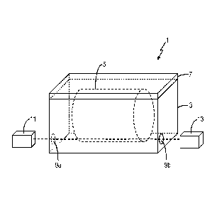
11 Figure 1 illustrates an apparatus 1 for monitoring and controlling the
whisky maturation
12 process, comprising a vessel 3 to house a whisky cask 5. The vessel 3 is
rectangular box,
13 in this embodiment made of aluminium, and comprises a lid 7 to provide
access to the
14 vessel. The lid 7 is held in place using screws and has a rubber gasket
(not shown) such
that when the lid 7 is screwed down the vessel 3 is sealed. The vessel
provides an
16 expansion volume (i.e. the internal volume not occupied by the cask 5)
into which vapour
17 (e.g. ethanol vapour) from the cask may expand. As will be demonstrated
below,
18 experimental results show that this prevents further fluid loss from the
cask once an
19 equilibrium condition is reached.
21 Two apertures 9a, 9b are provided at opposing ends of the vessel,
defining an optical path
22 through the vessel. The apertures are sealed by way of calcium fluoride
(CaF2) windows
= 23 affixed thereto, although any suitable material for the
windows may be used.
24
Light from an infrared laser source 11, in this example a mid-infrared optical
parametric
26 oscillator source outputting 70mW at approximately 3306nm (although it
will be readily
27 apparent that any other suitable infrared light source may be employed),
is directed
28 through the apertures to a detector 13. This particular wavelength
coincides with the 0-H
29 and C-H stretch absorption bands of ethanol, and accordingly
transmission through the
vessel gives an indication of the presence of ethanol within the vessel. The
detector 13, in
31 this case a laser power meter, is connected to a data logger (not
shown), for example a
32 PC with a suitable data acquisition card, to record transmitted power as
a function of time.
33
34 In use, a background level for determining relative transmission or
absorption is obtained
without the cask 5 present in the vessel 3, although the background
measurement could
CA 2841215 2018-08-14
10
1 be taken immediately after the cask 5 is placed in the vessel 3 (before
or after the lid 7 is
2 in place) before any significant ethanol leakage occurs. Subsequently,
the lid 7 is secured
3 in place, creating a seal. As noted above, ethanol will leak out of the
cask 5 in the form of
4 ethanol vapour, which results in absorption of the laser light within the
vessel 3. This
absorption is detected by way of a reduction in optical power through the
vessel 3,
6 detected by the detector 13.
7
8 It is envisaged that an alternative embodiment of the invention comprises
the laser source
9 and power meter housed inside the vessel, in which case the apertures are
not required.
It is also envisaged that the monitoring system of the invention may be
employed as a
11 stand-alone monitoring system separate from a vessel, and employed to
monitor fluid loss
12 from a cask by detecting the presence of, say, ethanol vapour proximal
to the cask.
13
14 Figure 2 illustrates an exemplary graph 21 of relative transmission 23
as a function of time,
illustrating the leak rate of ethanol vapour from a test cask (5) housed
within a vessel.
16 Relative transmission is determined by dividing the measured optical
power at time t with
17 the background measurement obtained at the start of the process.
18
19 The applicant has noted that the leak rate decays overtime, tending
towards a plateau or
continuum value at which leakage from the cask will cease. Extrapolation of a
fit to the
21 experimental data, indicated by reference number 25, in this example
indicates that
22 equilibrium would be reached within two to three days. At this stage the
leakage from the
23 cask has stopped and the amount of ethanol vapour is fixed.
24
It is envisaged that instead of two apertures providing a pass-through, a
single aperture
26 may be provided with a retro-reflecting mirror inside the vessel ¨ for
example on the
27 opposing side of the vessel from the single aperture. The advantage
would be two-fold;
28 the absorption pathlength (and hence, sensitivity) would be doubled and
the vessel could
29 be monitored from one side.
31 The whisky cask 5 is shown sitting horizontally within the vessel,
however it will be
32 understood that the cask 5 may sit vertically or at any other
orientation. Furthermore,
33 while the vessel 3 is illustrated as being a rectangular box, any other
suitable shape of
34 container may be employed. For example, it may be useful to be
cylindrical or cask-
shaped in order to conform to existing storage facilities. Furthermore, while
the vessel of
CA 2841215 2018-08-14
11
1 this exemplary embodiment has been described as comprising aluminium, any
other
2 suitable material may be employed.
3
4 Of course a vessel may be sized to accommodate multiple whisky casks; a
particular
advantage being that the maturation process can be monitored and controlled
for all said
6 whisky casks at once, thus improving consistency of product between
casks. Alternatively,
7 several vessels could be linked by conduits such that conditions are
shared throughout,
8 whereupon a single one of said vessels could be monitored as described
herein in the
9 knowledge that conditions within or changes made to that vessel will
correspond with or
result in corresponding changes in conditions in the linked vessels.
11
12 While the exemplary embodiment has been described as monitoring the
presence of
13 ethanol within the vessel volume using a laser and a power meter, other
useful information
14 may be gleaned by employing a spectrometer or spectrophotometer to
analyse the
atmospheric composition within the vessel. The spectrometer may be of any
suitable kind,
16 for example a tuneable diode laser absorption spectrometer or an active
infrared
17 hyperspectral imaging system such as the Applicant's intra-cavity
optical parametric
18 oscillator based system. Thus, a detailed analysis of the composition of
the atmosphere
19 within the vessel might be determined in real-time.
21 The foregoing description of the invention provides an apparatus and a
method that first
22 and foremost prevents fluid loss from the cask once an equilibrium
position has been
23 reached.
24
By addition of a monitoring means, such as a light source and corresponding
detector, the
26 apparatus and method also allows the level of ethanol vapour leaking
from the cask to be
27 monitored. Optionally, the atmospheric composition can also be
determined. The cask is
28 also protected from external influences such as airborne pollutants.
29
Furthermore, the invention provides for a system and a method for controlling
the
31 maturation process. It has been found that simply sealing casks, for
example by shrink-
32 wrapping, does eliminate fluid loss however it also affects the
maturation process because
33 ingress of air into the cask from the surroundings is also prevented.
This is expected to be
34 of significant detriment to the taste of the whisky ¨ whisky should be
allowed to "breathe"
as it matures.
CA 2841215 2018-08-14
12
1
2 To remedy this issue, the vessel provides an expansion volume.
Furthermore,
3 environmental conditions within the vessel 3, and particularly the
expansion volume, can
4 be controlled throughout the maturation period. The system comprises a
control system
that allows the pressure within the vessel 3 to be controlled, as well as the
relative
6 humidity and atmospheric composition and of course temperature. This
control may
7 comprise maintaining the same environmental conditions throughout an
entire maturation
8 process or alternatively varying the environmental conditions as
required. By controlling
9 the environmental conditions the maturation process of the whisky can
also be controlled.
11 It is envisaged that substances may be added to the vessel during the
maturation process
12 to simulate desirable atmospheric conditions. For example, salt water
could be injected to
13 simulate the sea air of a shore-side maturation location.
14
In a particular embodiment of the invention, the control system is used to
maintain a small
16 positive atmospheric pressure within the sealed vessel. Accordingly, the
fluid loss from
17 the cask resulting from the angels' share is minimised while still
allowing for air (oxygen)
18 ingress into the cask to allow the whisky to mature properly.
19
As an extension of this embodiment, the vessel may be sized to provide
sufficient
21 atmospheric oxygen for an entire maturation process or portion thereof.
As described
22 above, the partial pressure of ethanol within the vessel resulting from
the angels' share will
23 plateau over the course of, say, a few days yet proper oxygenation is
provided for over the
24 course of a number of years. If necessary, the vessel can be purged and
refilled every few
years. Even with regular purging, the anticipated loss to the angels' share
will be
26 significantly reduced over the entire maturation process.
27
28 By way of example, it is found that the ratio of water loss to ethanol
loss from a cask is
29 dependent on the prevailing atmospheric conditions; principally relative
humidity and
temperature, although other conditions may also have an effect. For example,
higher
31 temperatures are found to increase losses of both ethanol and water.
Higher humidity
32 results in increased ethanol loss (relative to water) and lower humidity
results in increased
33 water loss (relative to ethanol). The system described herein allows
these conditions
34 (temperature and relative humidity) to be controlled, thus controlling
the maturation
process.
CA 2841215 2018-08-14
13
1
2 One particular use for this system will be in the event that testing
during the maturation
3 process reveals some issue with the whisky that can be remedied by
varying the
4 atmospheric conditions. For example, if it was deemed that increased
water loss was
required, relative humidity could be reduced. In this way, a specific ethanol
content can be
6 targeted, particularly during the final stages of the maturation process.
This may, for
7 example, be used to increase alcohol content of whisky or to reduce the
alcohol content of
8 wine in the final product ¨ as is often required in the industry.
9
A further application of the present invention is to detect leaks in a cask,
whereby the cask
11 is inserted into the vessel and leakage into the vessel monitored as a
function of time to
12 determine the presence of a leak and quantify the extent of the leak.
This is preferably
13 carried out before filling with whisky ¨ for example by filling with a
test gas. It is envisaged
14 that imaging systems (such as the applicant's active infrared
hyperspectral imaging
system) may be employed to identify the location and/or the size of any leaks
in the cask.
16
17 The invention provides an apparatus and a method that reduces fluid loss
from a cask
18 during a maturation process by sealably enclosing the cask in a vessel
that provides an
19 expansion volume to receive fluid vapour from the cask, a monitoring
system and a
method that monitors fluid loss from a cask during a maturation process using
a light
21 source and a detector to determine the presence of fluid vapour in the
vicinity of the cask,
22 a corresponding system for controlling a maturation process in which
environmental
23 conditions are controlled, and a cask leak testing system and method
making use of the
24 above.
26 Various modifications may be made within the scope of the invention as
herein intended.
27 For example, and as stated above, while specific examples are described
in relation to the
28 maturation of whisky in casks, similar apparatus, methods and systems
may be employed
29 in the maturation of bourbon and other spirits, wines, other alcoholic
beverages, and other
fluids (e.g. balsamic vinegar) that are matured in casks.
31
CA 2841215 2018-08-14