Note: Descriptions are shown in the official language in which they were submitted.
CA 02841740 2014-01-14
WO 2012/103310 PCT/US2012/022689
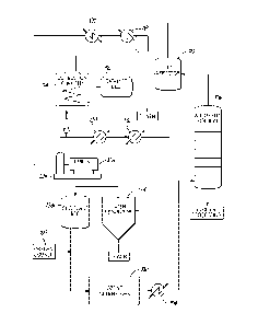
PROCESS FOR RECONDITIONING A GAS FROM THE OZONIZING OF AN
UNSATURATED FATTY ACID
FIELD OF THE INVENTION
[0001] The present invention relates to a process for recycling a depleted
gas
from the ozonizing of an ethylenically unsaturated compound, and, more
particularly,
reusing in further ozonizing reactions a portion of the depleted gas after
reconditioning.
BACKGROUND OF THE INVENTION
[0002] Azelaic acid and pelargonic acid can be produced in commercial
quantities
via an oxidative cleavage of an alkenyl unit (i.e., double bond between two
carbon
atoms) in oleic acid. For example, azelaic acid has been prepared from oleic
acid by
oxidation with chromium sulfate. However, because stoichiometric use of
chromium
reagents is undesirable, a more efficient oxidation approach utilizing ozone
was
developed.
[0003] The basic process is best understood by referring to the description
in the
accompanying FIG. 1, which is a diagrammatic flow chart indicating the pieces
of
equipment used and their relationship in the ozonolysis process. This process
involves
reacting an ethylenically unsaturated compound, such as oleic acid, with ozone
in an
absorber column 13 to form an ozonide. The ozone is provided by a continuous
closed
system 12 that recirculates and recycles the ozone enriched gas. The ozonide
is
transferred from the absorber column 13 to one or more reaction chambers 37
where it
is decomposed in the presence of additional oxygen and optional ozone to form
a
mixture of compounds including monobasic and dibasic acids, the mixture being
referred to as mixed oxidation products (MOP). Monobasic acids and dibasic
acids are
then separated and individually processed in a series of stills 40 and 52,
condensers 43
and 55, extractor 64, and evaporators 70 to remove compounds and undesired
fractions
among the range of molecular weights of monobasic and dibasic acids produced.
The
separated and purified monobasic and dibasic acids are then stored in storage
tanks 46
and storage bins 76.
[0004] Ozonized gas is fed into the absorber 13 by a continuous closed
system 12
through which the gas circulates. In the closed system 12, the gas is
recycled, i.e., the
gas is reconditioned for reuse multiple times in the absorber 13. The closed
system 12
reconditions the gas by removing organic compounds and water from the gas,
restoring
the desired oxygen concentration, and generating the desired concentration of
ozone.
1
CA 02841740 2014-01-14
WO 2012/103310
PCT/US2012/022689
The closed system 12 maintains the desired predetermined oxygen concentration
by
Needing off a small portion of the spent gas and replacing the bled off
portion with
fresh oxygen gas from an oxygen supply 16. The gas is then passed through a
dehydrator 19 before being transferred to an ozone generator 22 which utilizes
electricity to generate ozone. From the ozone generator 22, the ozone and
oxygen
mixture passes to the absorber 13 in which its ozone content is absorbed by
the oleic
acid as further explained below. From the absorber 13, the oxygen gas, now
substantially devoid of ozone, passes to an electrostatic precipitator 25,
which removes
any contaminating fine mist organic compounds that may have been picked up in
the
absorber 13. The decontaminated oxygen gas then passes from the electrostatic
precipitator 25 through a compression pump 28 to a cooler 31 before returning
to the
dehydrator 19, in which substantially all moisture is removed from the gas,
thereby
completing a pass through the closed system 12. Between the cooler 31 and
dehydrator
19, a portion of the gas may be bled from the closed system 12 through a valve
to one or
more reaction chambers 37 for reaction with the ozonide to form the MOP.
[0005] While the process and apparatus described above generates organic
acids
such as azelaic and pelargonic acids from longer chain unsaturated organic
acids such
as oleic acid, deficiencies exist with respect to personnel safety, system
efficiencies and
equipment longevity. In particular, a gas containing a relatively high
concentration of
oxygen that is contaminated with organic compounds can foul the equipment used
in
the process and may explode if exposed to an ignition source. Thus, processes
that
improve the efficiency of removal of the organic compounds will improve
operation
efficiency by decreasing fouling of downstream equipment and improve safety by
decreasing the risk of explosion. With regard to the explosion concern, it has
been
observed that electrostatic precipitators have caused explosions when used
with oxygen
gases that are contaminated with organic compounds. As such, new and improved
processes and apparatus are needed.
SUMMARY OF THE INVENTION
[0006] Described herein are processes and gas recycling systems useful for
reconditioning a depleted gas from an absorber column in which an ozonizing
reaction
is conducted. The process is conducted in a closed system and includes the
steps of
removing organic compounds from the depleted gas, and compressing and drying
the
organic-free depleted gas. The process further includes reestablishing the
desired ratio
of oxygen to substantially non-reactive gas in the gas upstream of the ozone
generator
2
CA 02841740 2014-01-14
WO 2012/103310 PCT/US2012/022689
by removing a portion of the depleted gas and replacing the removed portion
with a
quantity of fresh oxygen gas, thereby forming a replenished gas. The
replenished gas is
then passed through an ozone generator to establish the desired ozone
concentration
thereby forming an ozone enriched gas. Finally, the ozone enriched gas is
reintroduced
into the absorber column for use in the ozonizing reaction.
BRIEF DESCRIPTION OF THE DRAWINGS
[0007] FIG. 1 is a schematic representation of an oleic acid ozonolysis
plant.
[0008] FIG. 2 is a schematic representation of an improved process for
reconditioning an oxygen-containing gas from an ozonizing reaction in
accordance with
embodiments of the invention.
[0009] FIG. 3 is a schematic representation of a wet arrestor in accordance
with
embodiments of the invention.
DETAILED DESCRIPTION OF THE INVENTION
[0010] The gas recycling system is used to circulate and recondition
depleted gas
from an absorber column in which an ozonizing reaction is conducted. In the
reaction,
ozone is reacted with an unsaturated fatty acid, such as oleic acid, in the
absorber
column to form an ozonide of the fatty acid at the unsaturated bond. The
ozonide
leaves the absorber column and is oxidized in a series of oxidation reactions
to yield a
mixture of a dibasic acid, such as azaleic acid, and a monobasic acid, such as
pelargonic
acid. The desired monobasic and dibasic acids may be purified from by-products
and
each other in a series of distillation, extraction, and crystallization steps.
The recycle
gas system is useful to recondition the depleted gas from the absorber and as
shown in
Fig. 2, provides a significant improvement in efficiency and safety over the
recycle gas
system shown in Fig. 1.
[oon] In the present system, pure oxygen from an oxygen source 100 is
combined with the depleted gas to establish a predetermined oxygen
concentration with
the balance of the gas being a gas or a mixture of gases that is substantially
non-reactive
in the ozonizing system. This gas is then fed into the ozone generators 102
where some
of the oxygen is transformed into ozone by electrical discharge to form an
ozone
enriched gas. The ozone enriched gas contains about 0.5% to about 20% ozone
and
alternatively to about 2% to about 15%. The ozone-enriched gas may then be
cooled by
an ozone cooler 104 before going to the absorber column 106 where it is
contacted in a
counter-current flow with an unsaturated fatty acid such as oleic acid,
converting the
3
CA 02841740 2014-01-14
WO 2012/103310 PCT/US2012/022689
unsaturated fatty acid into an ozonide. During the ozonizing process that
occurs in the
absorber column, the ozone enriched gas is depleted of ozone and becomes
contaminated with organic compounds and water.
[0012] When using oleic acid as the liquid reactant, exemplary organic
compounds in the contaminated depleted gas include short chain monobasic acids
having one to three carbons which may be in approximately the following
concentrations: formic acid ¨ about 40% to about 70%; acetic acid ¨ about 15%
to about
30%; propionic acid ¨ about 4% to about 10%. Under some circumstances, the
organic
compounds in the contaminated depleted gas may also include small quantities,
i.e.,
less than about 0.15% each, of the liquid reactant and desired products, i.e.,
oleic acid,
pelargonic acid, and azaleic acid.
[0013] The organic compounds and water must be removed from the depleted
gas before recycling the gas to the ozone generators 102. Organic compounds
are
typically removed from a gas by a combination of scrubbers and oxidizers.
However, a
gas having organic contaminants and a high concentration of oxygen is a
significant
explosion risk. To minimize the risk, the depleted gas is first passed through
a wet
arrestor 110 to prevent flashback from the oxidizer system to the absorber
column 106.
It was surprisingly discovered that the wet arrestor 110 performs the dual
function of
both preventing flashback to the absorber column 106 from downstream
equipment,
and removing organic compounds from the depleted gas. Typically, these two
functions
are performed by at least two pieces of equipment: 1) a flash arrestor to
prevent
flashback and 2) a scrubber or oxidizer system to remove organic compounds.
The wet
arrestor 110 not only performs both of these functions, but also cools the
depleted gas
and saturates the depleted gas with water vapor. Cooling the depleted gas
improves the
efficiency with which organic compounds are removed by the water in the wet
arrestor
110 and saturation of the depleted gas with water vapor significantly lowers
the risk of
explosion of the organic contaminated depleted gas. The wet arrestor no is
capable of
performing these functions because the dimensions of the wet arrestor and its
internal
components are specially matched to the flow rate of the depleted gas and the
operating
conditions of the system.
[0014] With reference to FIG. 3, the wet arrestor 110 includes a large
pressurized
container 200 having a lower portion 202, a middle portion 204, and an upper
portion
206. Depleted gas enters the lower portion 202 of the pressurized container
200, which
is filled with a volume of water 210, and passes through the volume of water
210. As the
depleted gas passes through the volume of water 210 in the form of bubbles
208, a
4
CA 02841740 2014-01-14
WO 2012/103310 PCT/US2012/022689
portion of the organic compounds passes both in the vapor phase and as
discrete liquid
droplets from the depleted gas into the volume of water 210 thereby removing
this
portion of organic compounds from the depleted gas. The portion of organic
compounds that pass from the depleted gas to the volume of water 210 may
include
water soluble organic compounds that go into solution with the volume of water
as well
as water insoluble organic compounds that exist as a discrete phase in the
volume of
water.
[0015] As the depleted gas bubbles 208 reach the surface of the water 212,
the
depleted gas enters the middle portion 204 of the pressurized container 200
where the
depleted gas 208 contains entrained droplets of liquid water 216. The depleted
gas with
entrained water 216 is pushed through the middle portion 204 of the
pressurized
container 200 by the positive pressure generated by the flow of depleted gas
into the
lower portion 202 of the chamber 200. At the upper end of the middle portion
204, the
depleted gas with entrained water 216 passes through a demister pad 218 that
removes
the entrained water 216. The depleted gas less entrained water, shown as
closed circles
220, exits the demister pad 218 into the upper portion 206 of the pressurized
container
200 where it exits the pressurized container 200 through an exit 222 as a
depleted gas
albeit saturated with water vapor.
[comb] The lower portion 202 of the pressurized container 200, filled with
a
volume of water 210, includes a gas inlet 224, a water inlet 226, a water
outlet 228, and
a drain 230. The gas inlet 224 is configured so that the depleted gas is
introduced as
small bubbles 208 into the volume of water 210 in the lower portion 202. In
one
embodiment, the gas inlet 224 includes a gas distribution tube 234 that
extends into the
pressurized container 200 and a plurality of sparge lines 236 along the length
of the gas
distribution tube 234. The plurality of sparge lines 236 extends from the gas
distribution tube 234 into the volume of water 210, and distributes the
depleted gas into
the volume of water 210 evenly from the gas inlet 224. Each of the plurality
of sparge
lines 236 includes a plurality of openings configured to allow the depleted
gas to pass
into the water 210 from the plurality of sparge lines 236. The openings in the
sparge
lines 236 have a length that typically ranges in size between about 0.1 inches
(about 0.3
cm) to about 0.25 inches (about 0.8 cm) and a width perpendicular to the
length that
typically ranges in size between about 0.1 inches (about 0.3 cm) and about
0.25 inches
(about 0.8 cm). A portion of the organic compounds passes from the depleted
gas into
the water as the bubbles 208 pass through the volume of water 210. The sizing
and
number of openings in the sparge lines 236 are adjusted to create a high
surface area of
CA 02841740 2014-01-14
WO 2012/103310 PCT/US2012/022689
bubble surface in the volume of water 210 to thereby more efficiently transfer
the
organic compounds to the volume of water 210.
[0017] The volume of water 210 above the plurality of sparge lines 236 is
sufficient so that about 80% to about 90% of the organic compounds pass from
the
depleted gas into the volume of water 210. The volume of water 210 in the
pressurized
container 200 may be controlled by adjusting the flow of water into the
pressurized
container 200 through the water inlet 226, the flow of water out of the
container
through the water outlet 228, or both. The volume of water flowing into and
out of the
pressurized container 200 may be monitored such as with a rotameter 238. The
flow of
water into and out of the container 200 may be controlled, such as with a
valve, so that
the volume of water 210 into the container 200 is maintained at a level
sufficient to
prevent flashback to the absorber column 106 from downstream equipment, remove
organic compounds from the depleted gas bubbling through the water, cool the
depleted gas, and saturate the depleted gas with water vapor. The water outlet
228
allows water that includes removed soluble and insoluble organic compounds to
exit the
pressurized container 200. The volume of water exiting the pressurized
container 200
through the water outlet 228 is approximately equal to the volume entering the
pressurized container through the water inlet 226 thereby maintaining a
generally
constant volume of water 210. The flow of water into and out of the
pressurized
container 200 may be controlled to optimize the removal of organic compounds
from
the depleted gas. For example, if the volume of water passing into and out of
the
pressurized container is too low, then the water could become saturated with
organic
compounds or be warmed to an extent that decreases the efficiency with which
compounds transfer from the depleted gas to the volume of water 210. The drain
230
may also be used to adjust the level of water in the pressurized container
200, but this
typically remains closed except for maintenance or repair purposes.
[0018] As mentioned above, the depleted gas in the middle portion 204 of
the
pressurized container 200 will include entrained liquid droplets of water 216,
which can
include organic compounds in addition to water. The entrained water 216 is
removed
from the depleted gas by the demister pad 218 located at the upper edge of the
middle
portion 204 of the pressurized container 200. In one embodiment, the demister
pad
218 has a thickness in a range between about 6 inches to about 12 inches, a
width in a
range between about 2 feet to about 6 feet, and a length in a range between
about 2 feet
to about 6 feet when the thickness, the width, and the length measurements are
made
perpendicular to one another. The mesh pad is typically made of a non-reactive
metal
6
CA 02841740 2014-01-14
WO 2012/103310 PCT/US2012/022689
such as stainless steel and the mesh has a density sufficient to trap the
entrained water
216 in the fibers of the mesh forming the demister pad 218. The entrained
water 216
becomes entrapped in the fibers of the mesh due to the velocity of the
depleted gas
through the demister pad 218. If the velocity is too low, then a portion of
the water
entrained 216 in the depleted gas can pass through the demister pad 218
without being
trapped by the mesh of the demister pad 218. If the velocity of the depleted
gas is too
high, then the water entrained 216 in the depleted gas will Now through the
demister
pad 218 or can be blown off the pad after being originally entrapped.
Generally, the
velocity of the depleted gas passing through the demister pad 218 ranges
between about
2 feet/sec and about eleven feet/sec. The water droplets trapped in the
demister pad
drop back into the volume of water 210 in the lower portion 202 of the
pressurized
container 200 where the water will eventually exit the container 200 via the
water
outlet 228.
[0019] In some embodiments, the water vapor saturated depleted gas is next
passed into a heat exchanger 112 and heated up to about 600 F. The heat
exchanger 112
transfers residual heat into the gas from the downstream combustion and
catalyst
processes, described in further detail below.
[0020] The water-saturated depleted gas is then introduced into a
combustion
chamber 114 and further heated in the combustion chamber 114 for removal of
90% to
about 99% of the remaining organic compounds via oxidation of those compounds,
in a
catalytic oxidizer system, a thermal oxidizer system, or a combination of the
two
systems.
[0021] For the catalytic oxidizer system, the water-saturated depleted gas
is
heated to a temperature of at least about 600 F or alternatively in a range
between
about 600 F to about 850 F before being passed through a catalyst bed 116,
which
catalyzes the degradation of about 90% to about 99% of the remaining organic
compounds into water and carbon dioxide. The catalytic oxidizer 116 has the
added
benefit of converting carbon monoxide emitted from the ozone generators 102
into
carbon dioxide thereby preventing the unsafe build-up of potentially explosive
carbon
monoxide in the closed system 12. The catalyst bed 116 contains a commercially
available rare earth oxidation catalyst, such as a palladium, platinum,
molybdenum,
rhodium, technetium, ruthenium, tantalum, tungsten, rhenium, osmium, iridium,
and
combinations thereof on a substrate such as a standard silicon honeycomb. The
catalyst
Mocks can be standard sized blocks as is known in the art.
[0022] For a thermal oxidizer system, the water vapor-saturated depleted
gas is
7
CA 02841740 2014-01-14
WO 2012/103310
PCT/US2012/022689
heated in a combustion chamber 114 to temperatures sufficient to oxidize
between
about 90% to about 99% of the organic compounds. In this embodiment the water-
saturated depleted gas is heated to at least about 850 F or, alternatively, at
least about
2000 F.
[0023] After passing through the oxidizer system, the water-saturated
depleted
gas is passed through a water removal system. The water removal system cools
the
water vapor-saturated depleted gas with a cooling system to aid the removal of
the
water vapor. The cooling system may include a heat exchanger 112, a blower
precooler
120, a blower 124, a water cooler 130, a gas chiller 132, a water separator
134, and a
desiccant bed 136.
[0024] The heat exchanger 112 cools the water-saturated depleted gas to
below
about 300 F, as described above. The blower precooler 120 further cools the
water-
saturated depleted gas to below about 120 F.
[0025] The water vapor-saturated depleted gas is then compressed in blower
124.
In an exemplary embodiment, the blower 124 may be driven by a turbine 126,
which
may in turn be powered by an electric motor, high pressure steam, or some
other power
device. The pressure of the depleted gas entering blower 124 is about 1.5
psig. The
Mower 124 increases the pressure of the depleted gas to at least about 10
psig, or
alternatively to a range between about 15 psig and about 20 psig.
[0026] The compressed depleted gas is cooled with cooling water in a gas
cooler
130 to below about 120 F, or alternatively to about 100 F. The compressed
oxygen-
depleted gas is further cooled using a refrigerant to less than 50 F, or
alternatively to
about 35 F, in a gas chiller 132. The refrigerated depleted gas passes then
through a
water separator 134 where most of the water, i.e., about 80% to about 90%, is
removed.
The depleted gas at this stage has a relative humidity that corresponds to a
dew point
below about -30 F, or alternatively below about -40 F. About 99% of the
remaining
water is removed by passing the depleted gas through a desiccant bed 136. The
desiccant bed may be, for example, activated alumina, silica gel, or other
desiccants as
are known in the art. The depleted gas at this stage has a relative humidity
corresponding to a dew point below about -50 F or alternatively to about -60
F.
[0027] After the removal of organic compounds and water vapor from the
depleted gas, the oxygen and ozone concentrations of the depleted gas are
replenished
in a replenishing system. First, a portion of the depleted gas is removed from
circulation through a valve where it may be vented into the atmosphere or used
in
another process. Then, the removed portion of gas is replaced with a quantity
of fresh
8
CA 02841740 2014-01-14
WO 2012/103310 PCT/US2012/022689
oxygen from the oxygen supply 100 sufficient to achieve the desired oxygen
concentration of from about 10% to about 99.9% with the balance being a gas or
mixture of gases that is substantially non-reactive in the ozonizing reaction
or the
ozonolysis system. The gas having been restored to the desired oxygen
concentration is
referred to as replenished gas. The fresh oxygen has an oxygen concentration
that is
sufficient to achieve the desired oxygen concentration in the replenished gas.
In one
embodiment, the fresh oxygen is a pure oxygen gas having at least 99% oxygen.
[0028] The replenished gas is then passed through an ozone generator 102 to
form an ozone enriched gas. The ozone enriched gas has an ozone concentration
of
about 0.5% to about 20% and alternatively to about 2% to about 15%. The ozone
enriched gas may then be cooled in the ozone gas cooler 104 before being
reintroduced
into the absorber column 106 through an absorber column access valve.
[0029] The gas recycling system and methods described herein may be useful
to
recycle gas from the ozonizing of unsaturated acids. As mentioned above, the
gas
recycling system is particularly suited for use with an ozonolysis system that
breaks
down oleic acid into pelargonic acid and azelaic acid. However, the gas
recycling system
may be useful to recycle the gas used to break down other unsaturated acids
into
component carbon chains which form monobasic and dibasic acids via the
ozonolysis
reaction, or even other ethylenically unsaturated materials which do not
contain
carboxyl functionality. The unsaturated acids may generally have between 8 and
30
carbon atoms and one or more unsaturated carbon to carbon bonds. The monobasic
and dibasic acid products that result from the ozonolysis reaction are
determined by the
location of the one or more unsaturated carbon to carbon bonds in the
unsaturated
acid. The unsaturated acids may be isolated from biological sources, such as
plants,
animals, or microorganisms. Alternatively, the unsaturated acids may be
isolated from
petroleum sources and synthetic sources. Exemplary mono unsaturated acids and
their
respective potential oxidation products are included in the Table below.
Carbons Exemplary Unsaturated Exemplary Monobasic Exemplary Dibasic
Fatty Acid Product Product
Obtusilic acid Caproic acid Succinic acid
10 Caproleic acid Formic acid Azelaic acid
11 Undecenoic acid Formic acid Sebacic acid
12 Lauric acid Propionic acid Azelaic acid
14 Myristoleic acid Valeric acid Azelaic acid
16 Palmitoleic acid Heptanoic acid Azelaic acid
18 Petroselinic acid Lauric acid Adipic acid
18 Oleic acid Pelargonic acid Azelaic acid
18 Vaccenic acid Heptanoic acid Hendecanedioic acid
18 Octadecenoic acid Caproic acid Dodecanedioic acid
9
CA 02841740 2014-01-14
WO 2012/103310 PCT/US2012/022689
20 Gadoleic acid Undecanoic acid Azelaic acid
22 Cetoleic acid Undecanoic acid Hendecanedioic acid
22 Erucic acid Pelargonic acid Brassylic acid
24 Selacholeic acid Pelargonic acid Pentadecanedioic acid
26 Hexacosenoic acid Pelargonic acid Heptadecanedioic acid
30 Tricosenoic acid Pelargonic acid Heneicosanedioic acid
[0030] While the list above includes monounsaturated acids, it is
understood that
polyunsaturated acids could be utilized as well. The resulting monobasic acids
and
dibasic acids, and their respective derivatives, may be used for a number of
different
purposes such as in the preparation of lubricant base stocks, plasticizers,
lacquers,
herbicides, skin treatments, textile coning oils, flotation agents for mineral
refining,
fragrances, catalyst scavengers, corrosion inhibitors, metal cleaners,
polymerization
initiators, lithium complex greases, epoxy flexibilizers, thermosetting
unsaturated
polyester resins, polyamide hot melts, urethane elastomers, and elastomeric
fibers, wire
coatings and molding resins.
[0031] It will be appreciated that while the exemplary system described
herein
utilizes all of the described reconditioning elements, it is within the scope
of the
invention that some of the reconditioning elements may be omitted in some
embodiments. These and other modifications, methods and apparatus will become
readily apparent from this application without departing from the scope of the
invention and applicant intends to be bound only by the claims appended
hereto.