Note: Descriptions are shown in the official language in which they were submitted.
LIQUEFIER WITH PRESSURE-CONTROLLED LIQUEFACTION CHAMBER
[0001]
BACKGROUND OF THE INVENTION
Field of the invention
[0002] This invention relates to gas liquefaction systems, or
"liquefiers"; and more
particularly to a liquefier having an isolated liquefaction chamber adapted
for dynamic
pressure-control for achieving improved liquefaction efficiency.
Related Art
[0003] Gas liquefaction systems, also referred to as "liquefiers", are
well documented
in the art and generally comprise a vacuum insulated container known as a
Dewar, the Dewar
being adapted to receive at least a portion of a cryocooler for liquefying
gas, and further
comprising a storage portion for storing an amount of liquefied gas therein.
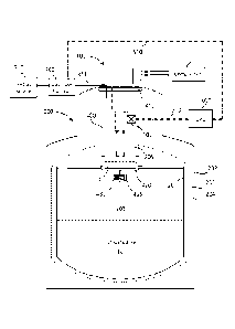
10004] FIG. 1 illustrates a liquefier comprising a Dewar 200 and a
cryocooler 100
extending within a neck portion 206 of the Dewar. Within these systems, such a
Dewar
generally comprises an outer shell 202, an inner shell 201, and volume 203
therebetween being
substantially evacuated of air to form a thermally insulated container.
Optionally, a thermal
shield 204 (shown in dashed lines), such as a foil or similar material, may be
further disposed
between the inner and outer shells of the Dewar. The Dewar further comprises a
storage body
portion 205 and the neck portion 206 extending therefrom. The Dewar is adapted
to store a
volume of liquefied cryogen within the storage body portion. A helium gas
source 310
generally feeds an input gas line 211 for supply of the gas to be liquefied. A
compressor 110
operates a first stage regenerator 101a for cooling a first stage 101b of the
cryocooler, and up
to several additional regenerators and cooling stages depending on the
cryocooler design. The
cryocooler 100 is illustrated as having three cooling stages comprising in
addition to the first
stage regenerator and first stage, a second stage regenerator 102a for cooling
a second stage
102b, and a third stage regenerator 103a for cooling a third stage 103b.
[0005] It is presently common for a cryocooler to comprise two or more
cooling
stages extending along a length of the cryocooler, such that a first stage
thereof is adapted to
1
CA 2841818 2017-12-20
CA 02841818 2014-01-13
WO 2013/010183
PCT/US2012/046966
pre-cool the gas and a subsequent stage is adapted to further cool the gas to
a temperature
sufficient for liquefaction. Moreover, each successive cooling stage typically
comprises less
surface area than the preceding stage, resulting in a cooling gradient along
the several
cryocooler stages.
[0006] Cryocoolers
for use in such liquefiers and reliquefiers generally include a
Gifford-McMahon (GM) type refrigerator or a pulse tube refrigerator; however
these
liquefiers may further include any type of refrigeration device for the
purpose of cooling
gases and condensing gas into a liquid phase. These liquefied gases are
typically referred to
as cryogenic liquids or cryogens.
[0007] Also
documented in the art are "reliquefiers-, which generally comprise a
liquefier that is adapted to circulate and re-liquefy gas within a closed or
semi-closed system.
[0008] FIG.2
illustrates such a reliquefier, which is substantially similar in design to
the liquefier of FIG.1. The reliquefier of FIG.2 further comprises equipment
320 coupled in
fluid communication with the Dewar for receiving an amount of liquid cryogen.
Subsequent
to using the liquid cryogen, evaporated gas is collected from the equipment
and recycled back
into the liquefier using a recirculator 315 such as a pump or similar device.
It should be noted
that the "equipment 320" may include one or more instruments, such as medical
or scientific
analytical instruments, among others, and is not limited to a single
instrument of any design.
Additionally, it should be noted that there exists a myriad of design
variations which
essentially recirculate collected gas back through a liquefier to foim a
closed or semi-closed
system.
[0009] These
liquefiers and reliquefiers, however, are limited with respect to
liquefaction efficiency, or the amount of liquefied cryogen that can be
generated using a
given cryocooler over a period of time. There is a continued need for
liquefiers having
improved liquefaction efficiency.
[0010] Of
importance to this invention are the thermodynamic properties associated
with cryogen gases. These properties are generally illustrated through a phase
diagram, such
as illustrated in FIG.3. In particular, the thermodynamic properties of helium
gas are of great
interest since liquefied helium is presently in high demand within a multitude
of industries.
[0011] Now turning
to Figure 3, a phase diagram depicts a liquefaction curve for
helium gas for various pressures (bar) and temperatures (Kelvin). The
hexagonal close-
packed (hcp) and body centered cubic (bcc) phases of the solid are shown for
completeness.
2
The liquefaction curve comprises a number of points at which helium gas
transitions to liquid
phase, the points collectively defining the liquefaction curve. A first
liquefaction point (b)
indicates a transition from gas-phase helium to a liquid-phase at a pressure
of about lbar (near
atmospheric pressure) which requires a temperature of about 4.22 K; this is
known as the
"boiling point" for helium-4, and hence point (b). A second liquefaction point
(c) indicates the
liquefaction of helium gas at a slightly increased pressure of about 2.27 bar
which requires a
temperature of about 5.20 K; this is known as the "critical point" for helium-
4. In view of the
liquefaction curve, it becomes recognizable that if a slightly higher pressure
can be provided
within the liquefaction chamber of the liquefier, liquefaction of helium gas
can be achieved at
slightly higher temperatures. Moreover, at these higher temperatures, most
cryocoolers will
be capable of increased cooling power. Thus, to take advantage of the higher
cooling power
of the cryocooler, one might develop a liquefier capable of liquefaction at
pressures above 1
bar, and more preferably between 1 bar and 2.27 bar.
[0012] The advantages of liquefying a gas at pressures above 1.0 bar
have been further
described in WIPO/PCT Publication No. WO 2011/139989, by Rillo et al., filed
May 02,
2011, and titled "GAS LIQUEFACTION SYSTEM AND METHOD". The Rillo system,
however, merely describes embodiments wherein the cryocooler is positioned
within the neck
of a large Dewar such that the entire storage portion of the Dewar must be
held at the elevated
liquefaction pressure. 'Ibis creates several serious problems: (i) Holding
large cryogenic
containers at high pressures is dangerous and further requires that the Dewar
meet rigid safety
requirements, thereby increasing the cost associated with the Dewar; (ii)
before extracting the
liquid cryogen, the Dewar pressure must be lowered to about 1.0 bar which
results in the loss
of a substantial amount of cryogen; and (iii) when lowering the pressure in
the Dewar and
removing the liquid cryogen from the Dewar, the system cannot simultaneously
continue the
liquefaction process at the optimum liquefaction pressure. To date, no
instrument for
liquefaction of gas has yet been developed that allows a gas to be liquefied
at elevated
pressures, stored at or near ambient pressures and further allows the user to
extract the liquid
cryogen from the Dewar while simultaneously continuing to liquefy gas at the
optimal
pressure. Such a system would also solve the problem of storing pressurized
liquids and gasses
at high pressures in large volume containers while realizing the benefits of
pressurized
liquefaction; i.e. increased efficiency. With increased efficiency, a smaller
liquefier would be
3
CA 2841818 2017-12-20
CA 02841818 2014-01-13
WO 2013/010183
PCT/US2012/046966
capable of replacing a larger liquefier while providing a similar liquefaction
rate.
Additionally, power would be conserved with the more efficient model.
SUMMARY OF THE INVENTION
[0013] The improved
gas liquefaction system disclosed herein provides an apparatus
and method for liquefying gases at pressures above 1.0 bar such that the
system is adapted to:
(i) take advantage of the higher cooling power of the cryocooler at higher
temperatures to
liquefy the gas more efficiently; (ii) eliminate the problem of storing a
cryogenic liquid at
high pressures; (iii) eliminate the need to lower the pressure in the storage
portion of the
Dewar to ambient pressure before removing the liquid cryogen; (iv) eliminate
the loss of
cryogen associated with lowering the pressure in the storage portion of the
Dewar to ambient
pressure; and (v) allow the liquefaction process to proceed simultaneously
while the user is
removing liquid cryogen from the storage portion of the Dewar. In particular
the system is
adapted to liquefy helium gas at an elevated pressure (and temperature) near
the critical point
of liquid helium for achieving improved liquefaction efficiency of helium. For
helium, the
pressure at the critical point is about 2.2 bar.
[0014] The
liquefaction system, or liquefier, described herein comprises a pressure-
controlled liquefaction chamber. A liquefaction region within the chamber is
hermetically
sealed and segregated from a storage portion of the Dewar. The liquefaction
region is adapted
to liquefy a cryogen gas at conditions near the critical point for the
particular gas. The
pressure-controlled liquefaction chamber further comprises a fluid collection
reservoir which
is in fluid communication with the storage portion of the Dewar through a
conduit extending
therebetween.
[0015] In various
embodiments, the liquefier is adapted to actively monitor and
dynamically regulate pressure within the liquefaction chamber for providing
efficient
liquefaction of gas. For example, a pressure sensor and/or a thermometer may
be coupled to a
CPU for measuring at least one of pressure and temperature within the
liquefaction region of
the liquefier. In this regard, the system is adapted to monitor liquefaction
conditions such as
pressure and temperature within the liquefaction chamber, and can further
regulate the
liquefaction of gas therein by increasing pressure within the liquefaction
chamber (inserting
high-pressure gas), decreasing pressure (exhausting gas), switching on/off the
cryocooler, or
other functions. Thus, the liquefier can be dynamically controlled for
optimizing liquefaction
conditions and thereby controlling the efficiency of the liquefier.
4
CA 02841818 2014-01-13
WO 2013/010183
PCT/US2012/046966
[0016] In certain
embodiments, a heat exchange region is foimed between an inner-
neck surface of the Dewar and an outer wall surface of the liquefaction
chamber. The heat
exchange region provides counter-flow heat exchange as cold gas escaping from
the storage
portion of the Dewar circulates about the heat exchange region and cools the
outer chamber
surface.
[0017] In certain
embodiments, the liquefaction system utilizes a series of control
components such as thermometers, pressure sensors, and other devices to
maintain the
liquefaction conditions within the pressure-controlled liquefaction chamber at
or near the
critical point for the select gas; for example at or near 2.2 bar and 5.2 K
for helium. The
control components are connected to a CPU for dynamic computerized control.
[0018] Other
features and benefits will be further recognized upon a review of the
detailed description of the preferred embodiments as set forth below.
BRIEF DESCRIPTION OF THE DRAWINGS
[0019] FIG. 1 is a
schematic illustrating the general components of a liquefier in
accordance with the prior art.
[0020] FIG. 2 is a
schematic illustrating the general components of a reliquefier in
accordance with the prior art.
[0021] FIG. 3
depicts a phase diagram for helium-4, and more particularly a
liquefaction curve extending between helium's boiling point and critical point
and associated
pressures and temperatures extending along the liquefaction curve.
[0022] FIG. 4
illustrates a liquefier having a pressure-controlled liquefaction
chamber being hermetically isolated from a storage portion of a surrounding
Dewar
container; a CPU is coupled to a gas flow control and one or more control
components for
dynamically controlling pressure within the liquefaction chamber.
[0023] FIG. 5
illustrates a reliquefier having a similar design to the liquefier of
FIG.4.
[0024] FIG.6
illustrates a CPU being coupled to a cryocooler, a gas flow control,
and number of control components such as pressure sensors, temperature
sensors, and an
exhaust valve; the CPU is adapted to dynamically control pressure within the
liquefaction
chamber.
CA 02841818 2014-01-13
WO 2013/010183
PCT/US2012/046966
[0025] FIG. 7A
illustrates a CPU being coupled to a gas flow control for
dynamically controlling high-pressure gas entering the liquefaction chamber;
the gas flow
control comprises a pressure regulator and a mass flow controller.
[0026] FIG. 7B
illustrates a CPU being coupled to a gas flow control for
dynamically controlling high-pressure gas entering the liquefaction chamber;
the gas flow
control comprises a plurality of pressure regulators being connected in series
with
corresponding mass flow controllers.
[0027] FIG. 8
illustrates A CPU being coupled to a gas flow control, a cryocooler,
and a plurality of control components including heating elements, temperature
sensors,
pressure sensors, exhaust valves, and heat exchange valves.
[0028] F1G.9
illustrates a pressure-controlled liquefaction chamber in accordance
with an embodiment, the liquefaction chamber further comprises a heat exchange
region for
providing counter-flow heat exchange with the chamber surface.
[0029] FIG.10
illustrates an isolation plate having a number of heat exchange valves
disposed thereon for use in the embodiment illustrated in FIG.9.
[0030] FIG.11
further illustrates the embodiment of FIGs 9-10 with control
components being lumped into a generic box for simplified illustration.
DETAILED DESCRIPTION OF THE PREFERRED EMBODIMENTS
[0031] In the
following description, for purposes of explanation and not limitation,
details and descriptions are set forth in order to provide a thorough
understanding of the
present invention. However, it will be apparent to those skilled in the art
that the present
invention may be practiced in other embodiments that depart from these details
and
descriptions without departing from the spirit and scope of the invention.
Certain
embodiments will be described below with reference to the drawings wherein
illustrative
features are denoted by reference numerals.
[0032] In a general
embodiment, a liquefier comprises a storage portion and a
liquefaction chamber that is sealed from the storage portion such that
liquefaction of gas is
performed within the liquefaction chamber under isolated conditions from the
storage
portion; i.e. elevated pressure. In this regard, the liquefaction region of
the chamber is
generally pressurized above atmospheric pressure during the process of gas
liquefaction,
whereas the storage portion maintains liquefied gas at atmospheric pressure
such that the
6
CA 02841818 2014-01-13
WO 2013/010183
PCT/US2012/046966
liquefied gas may be readily utilized without suspending the process of gas
liquefaction. The
liquefaction region is in fluid communication with the storage portion of the
liquefier through
at least one conduit extending from a fluid collection reservoir to the
storage portion. Thus as
liquid collects within the fluid reservoir of the liquefaction chamber it may
be transferred to
the storage portion through the conduit.
[0033] FIG.4
illustrates a liquefier in accordance with various embodiments. The
liquefier comprises a Dewar 200 having a storage portion 205 and a neck
portion 206
extending therefrom. The Dewar generally comprises an outer shell 202 and an
inner shell
201 nested within the outer shell to form a volume 203 therebetween. The
volume 203
between the outer shell and the inner shell is evacuated of air to provide
thermal insulation.
The vacuum region 203 of the Dewar may optionally contain a radiation shield
or an
additional shell 204 (shown with dashed lines). The liquefier may be adapted
with two or
more necks and sleeves, or other optional variations, however, for simplicity
of describing the
function of the system a single Dewar neck and will be shown in the drawings.
[0034] The
liquefier is further characterized in that the neck portion 206 is further
adapted to at least partially comprise a liquefaction chamber being
hermetically isolated from
the storage portion 205. The liquefaction chamber 400 comprises a tubular wall
within the
neck portion of the Dewar. The chamber may utilize a tubular portion of the
Dewar neck to
form the liquefaction chamber, or a concentrically-disposed tubular sleeve may
be integrated
within the Dewar neck to form the tubular wall. The inner-volume of the
chamber is also
referred to herein as the "liquefaction region" of the liquefier since gas is
liquefied therein. A
fluid collection reservoir 420 is disposed at a bottom end of the liquefaction
chamber,
wherein liquefied gas is gathered and at least temporarily stored prior to
transfer from the
liquefaction chamber to the storage portion of the liquefier. A conduit 430
connects the fluid
collection reservoir to the storage portion 205 of the Dewar, wherein an
amount of liquefied
gas 10 is stored within the storage portion for use at or near ambient
pressure.
[0035] A cryocooler
100 may comprise one or more cooling stages extending within
the liquefaction region of the liquefier. The liquefaction chamber may be
sealed with the
cryocooler or any bracket or plate 410 attached to a head portion of the
cryocooler such that
the region within the chamber may be hermetically isolated for providing
pressure-controlled
liquefaction at elevated pressure. The cryocooler can be of any type, but
generally may
comprise a multistage GM or pulse tube type cryocooler. A compressor 110 is
generally
coupled the cryocooler in accordance with known embodiments.
7
CA 02841818 2014-01-13
WO 2013/010183
PCT/US2012/046966
[0036] One or more
restriction elements 435, such as valves or heaters, can be
further connected to the conduit 430 such that the flow of liquid cryogen from
the fluid
reservoir 420 to the storage portion 205 can be regulated. Optionally, a
computer, or "CPU"
600, can be used to dynamically adjust the restriction element(s) for
regulating the flow
liquefied cryogen from the fluid reservoir to the storage portion.
[0037] The CPU 600
is generally connected to gas flow control 700 and one or more
control components 500 via respective control cables 610. The control
components 500 may
comprise one or more of: temperature sensors, pressure sensors, fluid level
sensors, various
valves, or other components useful in regulating temperature and pressure
within a closed-
system. The CPU is adapted with software for utilizing the control components
to monitor
liquefaction conditions within the liquefaction chamber, and further adapted
to adjust the
valves associated with the gas flow control, exhaust valves for venting the
chamber, or other
components.
[0038] Gas within
the liquefaction chamber is pressurized above 1.0 bar during
liquefaction; and in the case of helium pressure is ideally is maintained near
2.2 bar during
liquefaction. At this elevated pressure, the helium is liquefied with maximum
cooling power
being realized from the cryocooler and efficiency is significantly improved.
The pressure
within the liquefaction region is be regulated by CPU 600, which is coupled to
gas flow
control 700 through a control cable 610 as described above. Thus, a volume of
input gas can
be delivered at a pressure above one atmosphere into the sealed liquefaction
chamber 400,
thereby increasing pressure therein. As the gas condenses into liquid,
additional gas is
supplied to the system from an external gas source 310 via gas flow control
700 and the input
gas line 311 extending from the gas flow control to the liquefaction chamber
of the Dewar.
Utilizing the gas flow control 700 and control components 500 including one or
more
temperature sensors, pressure sensors, and exhaust valves among others, the
CPU can
precisely control the pressure in the sealed liquefaction chamber to maintain
the optimal
liquefaction parameters at all times, thereby achieving the maximum possible
liquefaction
efficiency.
[0039] F1G.5is a
schematic of a reliquefier in accordance with an embodiment
wherein the liquefier of FIG.4 is coupled to one or more instruments
collectively labeled
"Equipment 320". The equipment 320 is coupled to a He gas recirculator 315
such as a pump
or a network of components designed to collect evaporated gas from the
equipment, compress
the gas, and deliver the gas to the liquefaction chamber 400 through the gas
flow control 700.
8
CA 02841818 2014-01-13
WO 2013/010183
PCT/US2012/046966
[0040] FIG.6
further illustrates the pressure-controlled liquefaction chamber of
FIGs.4-5. The chamber 400 comprises a chamber body having a volume 406 for
liquefying
gas. A cryocooler 100 is sealed at a top end of the chamber and one or
multiple cooling
stages thereof extend into the volume 406. A fluid reservoir 420 is coupled to
a bottom plate
421 and sealed at a bottom end of the chamber 400. In this regard, the volume
406 extending
between the top end and bottom end of the chamber is hermetically sealed and
adapted to
provide a closed-system liquefaction environment capable of being pressurized
above 1.0 bar
for liquefaction of gas at elevated pressures.
[0041] Gas for
liquefaction within the chamber is provided by any gas source 310,
and regulated at gas flow control 700. Gas within the chamber 400 is liquefied
to form a
liquid cryogen 10 which collects in the bottom portion of the chamber at the
fluid collection
reservoir 420. A conduit 430 extends from the fluid reservoir 420, through the
bottom plate
421, into the storage portion of the Dewar. The conduit may further comprise
one or more
restriction elements 435, such as valves or heaters, to regulate a flow of
liquid cryogen from
the fluid reservoir 420 to the storage portion.
[0042] A CPU 600 is
connected to temperature probes 510a, 510b, and 510c
disposed within the liquefaction chamber 400. Temperature probes 510a; 510b
are positioned
on the cooling stages of the cryocooler for monitoring of a temperature of the
various stages.
Temperature probe 510c is positioned off of the cooling stages and within the
liquefaction
region of the chamber. In this regard, temperature probes can be positioned
for monitoring
temperature at various regions and components within the chamber. In addition
to the
temperature probes, CPU 600 is further connected to pressure sensor 520
disposed within the
liquefaction chamber. Although one pressure sensor is illustrated, it should
be understood that
several pressure sensors may be implemented. With the temperature and pressure
sensors, the
CPU can monitor liquefaction conditions such as chamber pressure and chamber
temperature
in real time.
[0043] The CPU 600
is further connected to gas flow control 700. In this regard,
pressure may be increased within the chamber 400 upon delivery of an amount of
high-
pressure gas. Given the known volume 406 of the liquefaction chamber and the
chamber
pressure determined at the pressure sensor 520, CPU 600 can be programmed to
determine a
volume of high pressure gas required for delivery into the chamber in order to
achieve an
optimum chamber pressure for efficient liquefaction of gas. As gas is
liquefied and
transferred to the storage portion, pressure within the chamber drops,
requiring a dynamic
9
CA 02841818 2014-01-13
WO 2013/010183
PCT/US2012/046966
monitoring of liquefaction conditions such that the input flow of gas through
the gas flow
control may be regulated to maintain optimum conditions.
[0044] If pressure within the chamber is too high, CPU 600 can vent an
amount of
gas within the chamber through exhaust valve 530. The vented gas will reduce
the pressure in
chamber 400, and may be collected for reuse such that precious helium may not
be lost.
[0045] A fluid level sensor (not illustrated) may be implemented at the
bottom end
of the chamber for determining a volume of liquefied cryogen within the fluid
collection
reservoir 420. Fluid level sensors are well known and described in the art and
thus are not
described in detail here. Any fluid level sensor can be positioned adjacent to
the fluid
reservoir and coupled to the CPU for dynamic monitoring of the fluid level
within the
reservoir.
[0046] CPU 600 is further connected to the cryocooler 100 such that the
cryocooler
may be switched on/off as may be required.
[0047] FIGs. 7A-7B further illustrate embodiments of the gas flow control
700.
[0048] In one embodiment as illustrated in FIG.7A, gas flow control 700
comprises
a pressure regulator 710 for regulating a pressure of gas to flow therefrom,
and a mass flow
controller 720. An inlet 701 is used to supply gas from a gas source, and an
outlet 702 is used
to deliver gas to the liquefaction chamber of a liquefier.
[0049] Pressure regulator 710 is illustrated as being a dynamic pressure
regulator
capable of computer control and coupled to the CPU such that pressure may be
actively
controlled through the regulator 710; however a static mechanical regulator,
such as the type
utilizing a valve and seat may be similarly incorporated.
[0050] The mass flow controller (MFC) 720 is designed and calibrated to
control a
specific type of fluid or gas at a particular range of flow rates; and in
these example the MFC
is designed for use with helium. The MFC can be given a setpoint from 0 to
100% of its full
scale range but is typically operated in the 10 to 90% of full scale where the
best accuracy is
achieved. The device will then control the rate of flow to the given setpoint.
The WC can be
either analog or digital. The MFC comprises an inlet port, an outlet port, a
mass flow sensor
and a proportional control valve. The MFC is fitted with a closed loop control
system which
is given an input signal by the CPU that it compares to the value from the
mass flow sensor
and adjusts the proportional valve accordingly to achieve the required flow.
The flow rate is
CA 02841818 2014-01-13
WO 2013/010183
PCT/US2012/046966
specified as a percentage of its calibrated full scale flow and is supplied to
the MFC as a
voltage signal. The Mass flow controller may require the supply gas to be
within a specific
pressure range, and thus it is coupled in series to a pressure regulator. For
example, low
pressure will starve the MFC of gas and it may fail to achieve its setpoint,
whereas high
pressure may cause erratic flow rates.
[0051] In another
embodiment. FIG.7B illustrates a gas flow control 700 comprising
an inlet 701 for delivering gas from a gas supply, and multiple outlets 702a;
702b; and 702c
each configured to deliver gas to the liquefier at a distinct pressure. In
this regard, gas can be
supplied from the gas flow control at various pressures for precision control
of chamber
pressure within the liquefaction chamber of the liquefier.
[0052] In order to
accomplish the multiple pressures provided by outlets A-C, a
number of regulators are adapted to step down the pressure from the supply
gas. For example,
regulator 710a may be set at a first high pressure; regulator 710b may be set
at a second
middle pressure less than the high pressure; and regulator 710c may be set at
a low pressure
less than the middle pressure; each of the low through high pressures will be
above 1.0 bar.
Each regulator 710(a-c) is independently coupled to a mass flow controller
720a; 720b; 720c
and coupled to a corresponding outlet (A-C). A CPU is connected to each of the
respective
MFC 'S. In this regard, high-pressure gas can be delivered to the liquefaction
chamber of the
liquefier at a variety of pressures.
[0053] FIG.8 is a
schematic of a CPU being connected to the gas flow control, a
cryocooler, one or more heating elements, one or more temperature sensors, one
or more
pressures sensors, one or more exhaust valves, and one or more heat exchange
valves
(discussed below). Moreover, up to any number "N" of individual components can
be
connected to the CPU and oriented within the liquefier for providing data
related to
liquefaction conditions or actively controlling the liquefaction conditions
within the chamber.
In this regard, the CPU is the heart of the system and can be programmed to
control various
components within the liquefier for monitoring and dynamically regulating
liquefaction
conditions within the liquefier.
[0054] While the
embodiment described FIGs. 4-7 above may be the simplest
embodiment of the invention, it should be noted that various enhancements
might be added to
further improve the thermal efficiency of the system.
11
CA 02841818 2014-01-13
WO 2013/010183
PCT/US2012/046966
[0055] For example,
in an embodiment 1000 illustrated in FIG. 9, the liquefaction
chamber 400 is disposed within the neck portion 800 of the Dewar. Moreover,
one or more
exhaust valves 530 may be disposed along the wall of the liquefaction chamber
and adapted
to vent or release excessive cryogen gas for the purpose of reducing pressure
within the
liquefaction region. The vented gas can be directed into a heat-exchange
region 810 formed
between the Dewar neck 800 and the outer surface of chamber 400. In this
regard, the one or
more valves 530 may be connected to a CPU for dynamic regulation of pressure
within the
liquefaction region of the liquefier. By adjusting pressure within the
liquefaction region, the
liquefaction rate and liquefaction efficiency can be controlled.
[0056] FIG.9
further illustrates a second use of the heat-exchange region for
providing a secondary cooling effect. For example, cold gas from the storage
portion of the
liquefier may be circulated about the heat exchange region 810. Regulation of
gas flowing in
and out of the heat exchange region is achieved using one or more heat
exchange valves
850a; 850b, as well as an exhaust valve 830 for venting gas from the heat
exchange region
810. Heat exchange valves 850a; 850b, and exhaust valve 830 are further
coupled to the CPU
for dynamic control. In this regard, cold gas from the storage portion can be
utilized to cool
the chamber wall, such that input gas flowing into the liquefaction chamber
may contact the
chamber wall for providing a secondary source of cooling to the gas as it
flows toward the
cryocooler.
[0057] Similar to
the pressure-controlled liquefaction chamber of FIG.6, the
chamber illustrated in FIG.9 further comprises temperature sensors 510a; 510b,
and pressure
sensor 520 coupled to the CPU. The conduit 430 extends through bottom plate
421 into the
storage portion, and is used to transfer liquefied cryogen from the fluid
collection reservoir
420 to the storage portion of the Dewar. One or more restriction elements 435,
such as valves
or heaters, can be connected to the conduit 430, and further connected to the
CPU, such that
the flow of liquid cryogen from the fluid reservoir 420 to the storage portion
can be
dynamically regulated.
[0058] The CPU is
coupled to the cryocooler for switching power to the cryocooler
between on/off. Moreover, the CPU is further coupled to the gas flow control
700 for
dynamically regulating an input gas flow into the liquefaction chamber as
described above.
[0059] FIG.10
illustrates a top view of the bottom plate 421 provided for sealing a
region between the storage portion and the heat exchange region according to
one
12
CA 02841818 2014-01-13
WO 2013/010183
PCT/US2012/046966
embodiment of the invention. The plate can be adapted with one or more heat
exchange
valves 850a; 850b for regulating gas flow between the storage portion and the
heat exchange
region. As described above, cold gas from an upper end of the storage portion,
wherein the
temperature is generally about 4.3 K for the embodiments utilizing helium, is
permitted to
flow into the heat exchange region using the one or more heat exchange valves.
In this
regard, gas flowing about the heat exchange region may contact the outer
surface of the
liquefaction chamber for providing counter-flow heat exchange about the sleeve
surface.
Moreover, an optional computer-controlled interface would enable dynamic
control of heat
exchange about the heat exchange region such that ideal liquefaction
conditions are
maintained about the liquefaction region, ideal storage conditions are
maintained about the
storage portion, and the combination of these conditions may be dynamically
modulated.
[0060] For purposes
of this invention, the valves 530; 830 used for venting gas from
the liquefaction chamber and heat exchange region, respectively, are referred
to herein as
"exhaust valves"; and the valves 850a; 850b used to regulate flow between the
storage
portion and the heat exchange region are referred to herein as "heat exchange
valves".
Moreover, the one or more valves adapted to regulate a flow through the
conduit between the
collection reservoir and the storage portion are herein referred to as
"restrictor valves", and
the one or more valves adapted to regulate input gas flow from the gas flow
control are
referred to herein as "input valves". In this regard, each of the various
valves may be
individually differentiated with respect to their distinct functions.
[0061] In certain
embodiments where a counter-flow heat exchange is not desired,
the liquefaction sleeve can be theimally isolated by a vacuum insulated shell,
and/or a
radiation shield. In this embodiment, the liquefaction chamber may comprise an
outer shell
portion and an inner shell portion (not illustrated), wherein a volume
disposed between the
inner and outer shell portions is substantially evacuated of air to form a
vacuum region
therein for thermal isolation. Additionally, a heat shield can be disposed
between, or adjacent
to, one or both of the inner and outer shell portions.
[0062] In the
various embodiments, gas within the liquefaction chamber is
pressurized near the critical point of the gas; for example helium gas is
maintained near 2.2
bar during liquefaction. At this elevated pressure, the helium or other gas is
liquefied with
maximum cooling power being realized from the cryocooler and efficiency is
significantly
improved. The pressure within the liquefaction chamber can be regulated with
the one or
more components as described above. For example, a volume of input gas can be
delivered at
13
CA 02841818 2014-01-13
WO 2013/010183
PCT/US2012/046966
a pressure above one atmosphere into the sealed liquefaction region, thereby
increasing
pressure therein. As the gas condenses into liquid, additional gas is supplied
to the system
from a gas source. The pressure of the input gas can be adjusted using a gas
flow control.
[0063] In the event
of high-pressure, for example above the critical pressure for the
target gas, the one or more exhaust valves can be adapted to release gas into
the heat
exchange region, or other compartments as described above.
[0064] To prevent
excessive accumulation of liquid within the fluid collection
reservoir, one or more methods can be implemented. For example, a stinger (not
illustrated)
may extend from a bottom stage of the cryocooler such that contact with
liquefied cryogen
may rapidly decrease the temperature of the stinger. One or more thermometers
may be
further attached to the cryocooler. or the stinger, such that temperature can
be monitored. The
thermometers can be connected to the CPU for dynamic regulation of the
conditions within
the liquefier. In this regard, the system can shut down upon sensing a rapid
decrease in
temperature which would indicate excessive liquid within the collection
reservoir.
Alternatively, the conduit extending from the fluid reservoir to the storage
portion may be
adapted to increase flow rate upon indication of excessive liquid in within
the collection
reservoir. The flow rate through the conduit can be adjusted by tuning the a
restrictor valve,
or adjusting heat using a heater element attached to the conduit. Moreover,
the input gas flow
can be adjusted at the gas flow control for regulating pressure within the
liquefaction
chamber. Each of the valves, temperature sensors (thermometers), pressure
sensors, or heater
elements can be connected to a CPU programmed to monitor dynamically adjust
liquefaction
conditions for dynamic control of liquefaction process.
[0065] In certain
embodiments, the fluid collection reservoir can be adapted to
contain about 1.0 liters of liquid gas. In other embodiments, the fluid
collection reservoir can
be adapted to contain between 0.1 and 5 liters of liquid gas. Depending on
user requirements,
the fluid collection reservoir can be adapted to contain any amount of
liquefied gas.
Furthermore, the storage portion of the Dewar can be configured to contain any
amount of
liquefied gas. In certain embodiments, the storage portion is adapted to
contain up to 1000
liters of liquid gas.
[0066] FIG.11
further illustrates a liquefier according to an embodiment as
illustrated in FIGs.9-10. The liquefaction chamber embodiment 1000 of FIG.9 is
being
illustrated without reference to various internal components for simplicity;
however the
14
CA 02841818 2014-01-13
WO 2013/010183
PCT/US2012/046966
components may be referenced in more detail as shown in FIG.9. CPU 600 is
coupled to
components 500, cryocooler 100, and gas flow control 700. Gas source 310
supplies gas to
the gas flow control 700. Gas flow control 700 further comprises a pressure
regulator 710 and
a mass flow controller 720. A liquid transfer port 900 may be provided for
accessing
liquefied gas contained within the storage portion and being stored at
atmospheric pressure.
The liquid transfer port generally comprises an orifice disposed near a top
surface of the
Dewar and being adapted to expose the storage portion for accessing an amount
of liquefied
gas therein. In this regard, the isolated liquefaction chamber may perform
continuous
liquefaction of gas therein at an elevated pressure while providing access to
liquid cryogen
being stored at atmospheric pressure within the storage portion of the Dewar.
Thus, the
system is not required to shut down for accessing liquid cryogen.
[0067] Accordingly,
a liquefier adapted for improved liquefaction efficiency
comprises a sealed liquefaction chamber and a storage portion. The sealed
liquefaction
chamber is adapted for liquefaction at elevated pressures, and particularly
adapted for
liquefaction near the critical pressure for a selected cryogen gas. The
pressure within the
liquefaction region is regulated by one or more of: (1) the pressure and/or
amount of input
gas directed into the liquefaction region using the gas flow control; (2) the
amount of gas
vented out of the liquefaction region through exhaust valves; or (3) the
amount of liquid
transferred from the fluid collection reservoir to the storage portion of the
Dewar.
[0068] Moreover,
the sealed liquefaction chamber may be surrounded by a heat
exchange region for providing a counter-flow heat exchange for secondary
cooling of the
liquefaction sleeve and gas contained within the liquefaction region.
[0069] In another
aspect of the invention, certain methods are disclosed for
improved liquefaction efficiency. In one embodiment, a method for providing
efficient
liquefaction of gas within a liquefier comprises: providing a liquefier having
a sealed
liquefaction chamber and a storage portion; regulating pressure within the
liquefaction
chamber near a critical liquefaction pressure for a selected gas; collecting
an amount of
liquefied gas in a fluid collection reservoir within the chamber; and
transferring said liquefied
gas to said storage portion of said liquefier through a conduit extending
therebetween.
[0070] The method
may further comprise: providing a heat exchange region
surrounding the sealed liquefaction chamber, the heat exchange region being
further sealed
from the storage portion except for one or more heat exchange valves
connecting
CA 02841818 2014-01-13
WO 2013/010183
PCT/US2012/046966
therebetween: and regulating a flow of gas about the heat exchange region
using the one or
more heat exchange valves for secondary cooling of said liquefaction region.
[0071] Other
variations would be recognized by those having skill in the art for
providing a liquefaction system with a pressurized well for extracting maximum
liquefaction
efficiency, and a region for heat exchange to enhance liquefaction
performance.
16