Note: Descriptions are shown in the official language in which they were submitted.
CA 02842425 2014-02-06
TRANSMISSION LINE SEGMENT COUPLER DEFINING FLUID PASSAGE WAYS
AND RELATED METHODS
Field of the Invention
[0001] The present invention relates to the field of
hydrocarbon resource recovery, and, more particularly, to
hydrocarbon resource recovery using RF heating.
Background of the Invention
[0002] Energy consumption worldwide is generally
increasing, and conventional hydrocarbon resources are being
consumed. In an attempt to meet demand, the exploitation of
unconventional resources may be desired. For example, highly
viscous hydrocarbon resources, such as heavy oils, may be
trapped in tar sands where their viscous nature does not
permit conventional oil well production. Estimates are that
trillions of barrels of oil reserves may be found in such tar
sand formations.
[0003] In some instances these tar sand deposits are
currently extracted via open-pit mining. Another approach for
in situ extraction for deeper deposits is known as Steam-
Assisted Gravity Drainage (SAGD). The heavy oil is immobile at
reservoir temperatures and therefore the oil is typically
heated to reduce its viscosity and mobilize the oil flow. In
SAGD, pairs of injector and producer wells are formed to be
laterally extending in the ground. Each pair of
injector/producer wells includes a lower producer well and an
upper injector well. The injector/production wells are
typically located in the pay zone of the subterranean
formation between an underburden layer and an overburden
layer.
(0004] The upper injector well is used to typically
inject steam, and the lower producer well collects the
1
CA 02842425 2014-02-06
heated crude oil or bitumen that flows out of the formation,
along with any water from the condensation of injected steam.
The injected steam forms a steam chamber that expands
vertically and horizontally in the formation. The heat from
the steam reduces the viscosity of the heavy crude
oil or bitumen which allows it to flow down into the lower
producer well where it is collected and recovered. The steam
and gases rise due to their lower density so that steam is not
produced at the lower producer well and steam trap control is
used to the same affect. Gases, such as methane, carbon
dioxide, and hydrogen sulfide, for example, may tend to rise
in the steam chamber and fill the void space left by the oil
defining an insulating layer above the steam. Oil and water
flow is by gravity driven drainage, into the lower producer
well.
[0005] Operating the injection and production wells at
approximately reservoir pressure may address the instability
problems that adversely affect high-pressure steam processes.
SAGD may produce a smooth, even production that can be as high
as 70% to 80% of the original oil in place (001P) in suitable
reservoirs. The SAGD process may be relatively sensitive to
shale streaks and other vertical barriers since, as the rock
is heated, differential thermal expansion causes fractures in
it, allowing steam and fluids to flow through. SAGD may be
twice as efficient as the older cyclic steam stimulation (CSS)
process.
[0006] Many countries in the world have large deposits of
oil sands, including the United States, Russia, and various
countries in the Middle East. Oil sands may represent as much
as two-thirds of the world's total petroleum resource, with at
least 1.7 trillion barrels in the Canadian Athabasca Oil
Sands, for example. At the present time, only Canada has a
large-scale commercial oil sands industry, though a small
2
CA 02842425 2014-02-06
amount of oil from oil sands is also produced in Venezuela.
Because of increasing oil sands production, Canada has become
the largest single supplier of oil and products to the United
States. Oil sands now are the source of almost half of
Canada's oil production, although due to the 2008 economic
downturn work on new projects has been deferred, while
Venezuelan production has been declining in recent years. Oil
is not yet produced from oil sands on a significant level in
other countries.
[0007] U.S. Published Patent Application No. 2010/0078163
to Banerjee et al. discloses a hydrocarbon recovery process
whereby three wells are provided, namely an uppermost well
used to inject water, a middle well used to introduce
microwaves into the reservoir, and a lowermost well for
production. A microwave generator generates microwaves which
are directed into a zone above the middle well through a
series of waveguides. The frequency of the microwaves is at a
frequency substantially equivalent to the resonant frequency
of the water so that the water is heated.
[0008] Along these lines, U.S. Published Application No.
2010/0294489 to Dreher, Jr. et al. discloses using microwaves
to provide heating. An activator is injected below the surface
and is heated by the microwaves, and the activator then heats
the heavy oil in the production well. U.S. Published
Application No. 2010/0294489 to Wheeler et al. discloses a
similar approach.
[0009] U.S. Patent No. 7,441,597 to Kasevich discloses
using a radio frequency generator to apply RF energy to a
horizontal portion of an RF well positioned above a horizontal
portion of an oil/gas producing well. The viscosity of the oil
is reduced as a result of the RF energy, which causes the oil
to drain due to gravity. The oil is recovered through the
oil/gas producing well.
3
CA 02842425 2014-02-06
[0010] Unfortunately, long production times, for example,
due to a failed start-up, to extract oil using SAGD may lead
to significant heat loss to the adjacent soil, excessive
consumption of steam, and a high cost for recovery.
Significant water resources are also typically used to recover
oil using SAGD, which impacts the environment. Limited water
resources may also limit oil recovery. SAGD is also not an
available process in permafrost regions, for example.
[0011] Moreover, despite the existence of systems that
utilize RF energy to provide heating, such systems may suffer
from inefficiencies as a result of impedance mismatches
between the RF source, transmission line, and/or antenna.
These mismatches become particularly acute with increased
heating of the subterranean formation. Moreover, such
applications may require high power levels that result in
relatively high transmission line temperatures that may result
in transmission failures. This may also cause problems with
thermal expansion as different materials may expand
differently, which may render it difficult to maintain
electrical and fluidic interconnections.
Summary of the Invention
[0012] It is therefore an object of the invention to
provide enhanced operating characteristics with RF heating for
hydrocarbon resource recovery systems and related methods.
[0013] These and other objects, features, and advantages
are provided by a transmission line segment coupler for
coupling together first and second coaxial transmission line
segments each comprising an inner tubular conductor and an
outer tubular conductor surrounding the inner tubular
conductor and a dielectric therebetween. The coupler includes
an outer tubular bearing body to be positioned within adjacent
open ends of the inner tubular conductors of the first and
4
CA 02842425 2014-02-06
second coaxial transmission line segments, and an inner
tubular bearing body configured to slidably move within the
outer tubular bearing body to define a linear bearing
therewith. The inner tubular bearing body is configured to
define a fluid passageway in communication with the adjacent
open ends of the inner tubular conductors of the first and
second coaxial transmission line segments. Accordingly, the
transmission line segment coupler advantageously provides for
mechanical, electrical, and fluidic coupling for transmission
line segments, while also accommodating material expansion due
to increased operating temperatures, such as in subterranean
formation heating applications for hydrocarbon resource
recovery.
[0014] More particularly, the inner tubular bearing body
may include opposing first and second ends extending outwardly
from the outer tubular bearing, and a medial portion extending
between the opposing first and second ends. The medial portion
of the inner tubular bearing body may have a length greater
than the outer tubular bearing body to define a linear bearing
travel limit. The transmission line segment coupler may
further include a respective sealing ring carried on each of
the first and second ends. Furthermore, the first end and the
medial portion may be threadably coupled together. Also, the
first end may be configured to be slidably received within the
open end of the tubular inner conductor of the first coaxial
transmission line segment, and the second end may configured
to be fixed to the open end of the tubular inner conductor of
the second coaxial transmission line segment.
[0015] The transmission line segment coupler may further
include a respective electrically conductive spring carried on
each end of the outer tubular bearing body and configured to
engage a respective open end of the respective inner tubular
conductor of the first and second coaxial transmission line
CA 02842425 2014-02-06
segments. More particularly, the outer tubular bearing body
may have a respective annular spring-receiving channel on an
outer surface thereof for each electrically conductive spring.
[0016] The transmission line segment coupler may further
include a dielectric support for the outer tubular bearing
body within a joint defined between adjacent tubular outer
conductors of the first and second coaxial transmission line
segments. In addition, the dielectric support may have at
least one fluid passageway therethrough. By way of example,
the outer tubular body may comprise brass, and the inner
tubular body may comprise copper.
[0017] A related apparatus for heating a hydrocarbon
resource in a subterranean formation having a wellbore
extending therein includes an RF antenna configured to be
positioned within the wellbore, an RF source, and a
transmission line configured to be positioned in the wellbore
and coupled between the RF antenna and the RF source. The
transmission line includes a plurality of transmission line
sections. Each transmission line section includes first and
second coaxial transmission line segments each comprising an
inner tubular conductor and an outer tubular conductor
surrounding the inner tubular conductor and a dielectric
therebetween, and a transmission line segment coupler, such as
the one described briefly above.
[0018] A related method is for making a transmission line
segment coupler for coupling together first and second coaxial
transmission line segments each comprising an inner tubular
conductor and an outer tubular conductor surrounding the inner
tubular conductor and a dielectric therebetween. The method
includes forming an outer tubular bearing body to be
positioned within adjacent open ends of the inner tubular
conductors of the first and second coaxial transmission line
segments. The method further includes forming an inner tubular
6
CA 02842425 2014-02-06
bearing body configured to slidably move within the outer
tubular bearing body to define a linear bearing therewith, the
inner tubular bearing body configured to define a fluid
passageway in communication with the adjacent open ends of the
inner tubular conductors of the first and second coaxial
transmission line segments, and positioning the inner tubular
bearing body within the outer tubular bearing body.
Brief Description of the Drawings
[0019] FIG. 1 is a schematic block diagram of an apparatus
for heating a hydrocarbon resource in a subterranean formation
in accordance with the present invention.
[0020] FIG. 2 is a schematic cross-sectional diagram
showing the transmission line, liquid dielectric balun, and
liquid tuning chambers from the apparatus of FIG. 1.
[0021] FIG. 3 is a cross-sectional perspective view of an
embodiment of the balun from the apparatus of FIG. 1.
[0022] FIG. 4 is a graph of choking reactance and resonant
frequency for the balun of FIG. 4 for different fluid levels.
[0023] FIG. 5 is a schematic cross-sectional view of an
embodiment of the lower end of the balun of FIG. 2, showing an
approach for adding/removing fluids and/or gasses therefrom.
[0024] FIG. 6 is a schematic circuit representation of the
balun of FIG. 2 which also includes a second balun.
[0025] FIG. 7 is a perspective view of a transmission line
segment coupler for use with the apparatus of FIG. 1.
[0026] FIG. 8 is an end view of the transmission line
segment coupler of FIG. 7.
[0027] FIG. 9 is a cross-sectional view of the transmission
line segment coupler of FIG. 7.
[0028] FIG. 10 is a cross-sectional view of the inner
conductor transmission line segment coupler of FIG. 7.
7
CA 02842425 2014-02-06
[0029] FIGS. 11 and 12 are fully exploded and partially
exploded views of the transmission line segment coupler of
FIG. 7, respectively.
[0030] FIG. 13 is a schematic block diagram of an exemplary
fluid source configuration for the apparatus of FIG. 1.
[0031] FIGS. 14-16 are flow diagrams illustrating method
aspects associated with the apparatus of FIG. 1.
[0032] FIG. 17 is a Smith chart illustrating operating
characteristics of various example liquid tuning chamber
configurations of the apparatus of FIG. 1.
Detailed Description of the Preferred Embodiments
[0033] The present invention will now be described more
fully hereinafter with reference to the accompanying drawings,
in which preferred embodiments of the invention are shown.
This invention may, however, be embodied in many different
forms and should not be construed as limited to the
embodiments set forth herein. Rather, these embodiments are
provided so that this disclosure will be thorough and
complete, and will fully convey the scope of the invention to
those skilled in the art. Like numbers refer to like elements
throughout.
[0034] Referring initially to FIG. 1, an apparatus 30 for
heating a hydrocarbon resource 31 (e.g., oil sands, etc.) in a
subterranean formation 32 having a wellbore 33 therein is
first described. In the illustrated example, the wellbore 33
is a laterally extending wellbore, although the system 30 may
be used with vertical or other wellbores in different
configurations. The system 30 further includes a radio
frequency (RF) source 34 for an RF antenna or transducer 35
that is positioned in the wellbore 33 adjacent the hydrocarbon
resource 31. The RF source 34 is positioned above the
subterranean formation 32, and may be an RF power generator,
8
CA 02842425 2014-02-06
for example. In an exemplary implementation, the laterally
extending wellbore 33 may extend several hundred meters within
the subterranean formation 32. Moreover, a typical laterally
extending wellbore 33 may have a diameter of about fourteen
inches or less, although larger wellbores may be used in some
implementations. Although not shown, in some embodiments a
second or producing wellbore may be used below the wellbore
33, such as would be found in a SAGD implementation, for
collection of petroleum, etc., released from the subterranean
formation 32 through heating.
[0035] A transmission line 38 extends within the wellbore
33 between the RE' source 34 and the RE' antenna 35. The RE'
antenna 35 includes an inner tubular conductor 36, an outer
tubular conductor 37, and other electrical aspects which
advantageously functions as a dipole antenna. As such, the RE'
source 34 may be used to differentially drive the RE' antenna
35. That is, the RE' antenna 35 may have a balanced design that
may be driven from an unbalanced drive signal. Typical
frequency range operation for a subterranean heating
application may be in a range of about 100 kHz to 10 MHz, and
at a power level of several megawatts, for example. However,
it will be appreciated that other configurations and operating
values may be used in different embodiments.
[0036] A dielectric may separate the inner tubular
conductor 36 and the outer tubular conductor 37, and these
conductors may be coaxial in some embodiments. However, it
will be appreciated that other antenna configurations may be
used in different embodiments. The outer tubular conductor 37
will typically be partially or completely exposed to radiate
RE' energy into the hydrocarbon resource 31.
[0037] The transmission line 38 may include a plurality of
separate segments which are successively coupled together as
the RE' antenna 35 is pushed or fed down the wellbore 33. The
9
CA 02842425 2014-02-06
transmission line 38 may also include an inner tubular
conductor 39 and an outer tubular conductor 40, which may be
separated by a dielectric material, for example. A dielectric
may also surround the outer tubular conductor 40, if desired.
In some configurations, the inner tubular conductor 39 and the
outer tubular conductor 40 may be coaxial, although other
transmission line conductor configurations may also be used in
different embodiments.
[0038] The apparatus 30 further includes a balun 45 coupled
to the transmission line 38 adjacent the RF antenna 35 within
the wellbore. Generally speaking, the balun 45 is used for
common-mode suppression of currents that result from feeding
the RE' antenna 35. More particularly, the balun 45 may be used
to confine much of the current to the RE' antenna 35, rather
than allowing it to travel back up the outer conductor 40 of
the transmission line, for example, to thereby help maintain
volumetric heating in the desired location while enabling
efficient, safe and electromagnetic interference (EMI)
compliant operation.
[0039] Yet, implementation of a balun deep within a
wellbore 33 adjacent the RE' antenna 35 (e.g., several hundred
meters down-hole), and without access once deployed, may be
problematic for typical electrically or mechanically
controlled baluns. Variable operating frequency is desirable
to facilitate optimum power transfer to the RE' antenna 35 and
subterranean formation 32, which changes over time with
heating. A quarter-wave type balun is well suited to the
operating characteristics of the borehole RE' antenna 35, due
to the relatively high aspect ratio of length to diameter and
relatively low loss, which results in enhanced system
efficiency. However, such a configuration is also relatively
narrow-band, meaning that it may require several adjustments
over the life of the well, and the relatively high physical
CA 02842425 2014-02-06
aspect ratio may also exacerbate voltage breakdown issues due
to small radial spacing between conductors.
[0040] More particularly, several difficulties may be
present when attempting to deploy a balun deep within the
ground for a hydrocarbon heating application. While some balun
configurations utilize a mechanical sliding short
configuration to change impedance settings, given the
relatively long wavelengths used for hydrocarbon heating, this
may make it difficult to implement such a mechanical tuning
configuration. That is, at typical wellbore dimensions and low
frequency operation, the required travel distance of a sliding
short to cover the desired operating range may be impractical.
Moreover, this may also necessitate a relatively complex
mechanical design to move the sliding short, which requires
movement past electrical insulators and a motor that may be
difficult to fit within the limited space constraints of the
wellbore. Moreover, it becomes prohibitively expensive to
significantly increase the dimensions of a typical wellbore
and transmission line to accommodate such mechanical tuning
features.
[0041] Turning additionally to FIGS. 2 and 3, rather than
utilizing a mechanical tuning configuration such as a sliding
short, the balun 45 advantageously comprises a body defining a
liquid chamber 50 configured to receive a quantity of
dielectric liquid 51 therein. Furthermore, the balun 45 may be
configured to receive an adjustable or changeable quantity of
dielectric liquid therein to advantageously provide adjustable
frequency operation as the operating characteristics of the RF
antenna 35 change during the heating process, requiring
operation at the changing frequencies.
[0042] More particularly, the body of the balun 45 includes
a tubular body surrounding the coaxial transmission line. The
tubular body includes an electrically conductive portion 52
11
CA 02842425 2014-02-06
and an insulating portion 53 coupled longitudinally between
the outer conductor 40 of the transmission line and the RF
antenna 35. The insulating portion 53 may comprise a solid
insulating material, although it may also comprise a non-solid
insulator in some embodiments. Furthermore, one or more
shorting conductors 54 (which may be implemented with an
annular conductive ring having a fluid opening(s)
therethrough) are electrically coupled between the
electrically conductive portion 52 and the coaxial
transmission line 38, and more particularly the outer
conductor 40 of the coaxial transmission line. The
electrically conductive portion 52 may serve as a cladding or
protective outer housing for the transmission line 38, and
will typically comprise a metal (e.g., steel, etc.) that is
sufficiently rigid to allow the transmission line to be pushed
down into the wellbore 33. The insulating portion may comprise
a dielectric material, such as a high-temperature composite
material, which is also sufficiently rigid to withstand
pushing down into the wellbore and elevated heat levels,
although other suitable insulator materials may also be used.
Alternate embodiments may also utilize a fluid or a gas to
form this insulator.
[0043] As will be discussed further below, in some
embodiments the space within the inner conductor 39 defines a
first passageway (e.g., a supply passageway) of a dielectric
liquid circuit, and the space between the inner conductor and
the outer conductor 40 defines a second passageway (e.g., a
return passageway) of a dielectric liquid circuit. The
dielectric liquid circuit allows a fluid (e.g., a liquid such
as mineral oil, silicon oil, de-ionized water, ester-based
oil, etc.) to be circulated through the coaxial transmission
line 38. This fluid may serve multiple functions, including to
keep the transmission line within desired operating
12
CA 02842425 2014-02-06
temperature ranges, since excessive heating of the
transmission line may otherwise occur given the relatively
high power used for supplying the RF antenna 35 and the
temperature of the hydrocarbon reservoir. Another function of
this fluid may be to enhance the high-voltage breakdown
characteristics of the coaxial structures, including the
balun. With the availability of the liquid circuit, the balun
45 advantageously further includes one or more valves 55 for
selectively communicating the dielectric liquid 51 from the
liquid chamber 50 in the fluid circuit (e.g., the return
passageway). This advantageously allows the liquid 51 to be
evacuated from the liquid chamber 50 as needed. By way of
example, the valve 55 may comprise a pressure-actuated valve,
and the apparatus 30 may further include a pressure (e.g.,
gas) source 28 coupled in fluid communication with the liquid
dielectric, to actuate the value as necessary. For example,
the gas source 28 may be a nitrogen or other suitable gas
source with a relatively low permittivity (Er) value, which
causes heavier fluid to escape via the valve 55. An alternate
embodiment may utilize an orifice in place of the valve, and
dynamic adjustment of gas pressure from the surface to vary
the liquid level in the liquid chamber 50.
[0044] The liquid chamber 50 is defined by a liquid-
blocking plug 56 positioned adjacent an end of the liquid
chamber and separating the balun 45 from the RF antenna 35.
That is, the liquid-blocking plug 56 keeps the dielectric
fluid 51 within the liquid chamber 50 and out of the RF
antenna 35, and defines the "bottom" or distal end of the
balun 45. A liquid dielectric source 29(and optionally
pressure/gas source) may supply the liquid chamber 50 via an
annulus at the well head through the passageway defined
between the electrically conductive portion 52 (i.e., outer
casing) and the outer conductor 40. In some embodiments,
13
CA 02842425 2014-02-06
another valve (not shown) is coupled between the inner
conductor 39 and the outer conductor 40 to supply dielectric
fluid from the cooling circuit (i.e., from the supply
passageway) into the liquid chamber 50 as needed. Another
approach is to run separate tubing between the outer conductor
40 and the casing (or external to the casing) for supplying or
evacuating dielectric fluid to or from the liquid chamber 50.
Generally speaking, it may be desirable to filter the
dielectric liquid 51 or otherwise replace dielectric liquid in
the liquid chamber with purified dielectric liquid to maintain
desired operating characteristics.
[0045] Accordingly, the above-described configuration may
advantageously be used to provide a relatively large-scale and
adjustable quarter-wave balun with fixed mechanical
dimensions, yet without the need for moving mechanical parts.
Rather, the balun 45 may advantageously be tuned to desired
resonant frequencies by using only an adjustable dielectric
fluid level and gas, which may readily be controlled from the
well head as needed. As such, this configuration
advantageously helps avoid difficulties associated with
implementing a sliding short or other mechanical tuning
configuration in the relatively space-constrained and remote
location within the wellbore 33. Moreover, use of the
dielectric fluid helps to provide improved dielectric
breakdown strength inside the balun 45 to allow for high-power
operation.
[0046] Operation of the balun will be further understood
with reference to the graph 57 of FIG. 4 showing simulated
performance for a model liquid balun 58. In the illustrated
example, a diameter of 3-1/8 inch was used for the inner
conductor, along with a diameter of ten inches for the outer
conductor, which had a 0.1 inch wall thickness. An overall
length of 100 m was used for the model balun 58, and the
14
CA 02842425 2014-02-06
various reactance/frequency values for various fluid lengths
ranging from 10 m to 100 m are shown. A dielectric fluid
(i.e., mineral oil) with a Er of 2.25 and tan(d) of
approximately 0 was used in the simulation.
[0047] It will be appreciated that the range of tunable
bandwidth is proportional to the square root of relative
permittivity as follows:
fh
= Ver
As will also be appreciated from the illustrated simulation
results, a lossy dielectric lowers common mode impedance, and
a lower characteristic impedance of the balun lowers common
mode impedance (e.g., a smaller outer diameter of the outer
conductor). A balun tuning range of Er - 150% was
advantageously achieved with the given test configuration,
although different tuning ranges may be achieved with
different configurations. As such, the balun 45 advantageously
provides for enhanced performance of the RE antenna 35 by
helping to block common mode currents along the outer
conductor 40, for example, which also allows for targeted
heating and compliance with surface radiation and safety
requirements.
[0048] Exemplary installation and operational details will
be further understood with reference to the flow diagram 100
of FIG. 14. Beginning at Block 101, the balun 45 is coupled or
connected to the RE antenna 35, and the transmission line 38
is then coupled to the opposite end of the balun in segments
as the assembled structure is fed down the wellbore 33, at
Block 102. The liquid chamber 50 is then filled using one of
the approaches described above to a desired starting operating
level, and heating may commence by supplying the RE signal to
CA 02842425 2014-02-06
the transmission line from the RF source 34, at Blocks 103,
104. It should be noted that the liquid chamber 50 need not
necessarily be filled before heating commences, in some
embodiments.
[0049] Over the service life of the well (which may last
several years), measurements may be taken (e.g., impedance,
common mode current, etc.) to determine when changes to the
fluid level are appropriate, at Blocks 105-106, to conclude
the method illustrated in FIG. 14 (Block 107). That is, a
reference index or database of expected operating values for
different fluid levels, such as those shown in FIG. 4, may be
used to determine an appropriate new dielectric fluid level to
provide desired operating characteristics, either by manual
configuration or a computer-implemented controller to change
the fluid levels appropriately. The dielectric fluid may also
be filtered or replaced as necessary to maintain desired
operating characteristics as well, as described above.
[0050] Referring additionally to FIGS. 5 through 9,
additional tuning adjustments may be provided in some
embodiments through the use of liquid tuning sections 60
included within the coaxial transmission line 38. More
particularly, in the example of FIG. 2, the transmission line
38 illustratively includes two tuning sections 60, although a
single tuning section or more than two tuning sections may be
used in different embodiments. Each tuning section 60 includes
the inner conductor 39, the outer conductor 40 surrounding the
inner conductor, and a liquid-blocking plug 61 between the
inner and outer conductors to define a tuning chamber
configured to receive a dielectric liquid 62 with a gas
headspace 63 thereabove. Thus, via adjustable liquid level,
the liquid tuning sections 60 may advantageously be used to
match the impedance of the antenna to the source of RF power,
as operating characteristics of the RF antenna change during
16
CA 02842425 2014-02-06
the heating process.
[0051] More particularly, gas and liquid sources may be
coupled in fluid communication with the tuning section 60 so
that a level of the liquid dielectric 62 relative to the gas
headspace 63 is adjustable. In the example of FIG. 5, an
external line 64 (e.g., a dielectric tube) may be adjacent the
transmission line and coupled in fluid communication with the
tuning chamber. Here, fluid coupling ports 65, 66 connect the
external line 64 to the fluid tuning chamber through the outer
cladding 52 and the outer conductor 40 as shown. It should be
noted that in some embodiments the line 64 may be run between
the cladding 52 and the outer conductor 40, rather than
external to the conductor, if desired.
[0052] In the illustrated embodiment, a valve 67 (e.g., a
pressure-actuated valve) is also included to allow evacuation
of the dielectric fluid 62 from the tuning chamber into the
cooling fluid circuit. Here, the cooling fluid circuit is
included entirely within the inner conductor 39 by running a
fluid line 68 inside the inner conductor. In this example, the
fluid line 68 is used for fluid supply, while fluid return
occurs through the remaining space within the inner conductor,
but the fluid line 68 may instead be used for cooling fluid
return in other embodiments, if desired. As described above, a
similar valve may also be used to provide dielectric fluid
from the cooling fluid circuit into the tuning chamber in some
embodiments, although where an external line 64 is present it
may be used to provide both liquid and gas supply and removal
without the need for separate valves opening to the cooling
fluid circuit. In some embodiments, a vaned annulus may be
used at the well head to provide multiple fluid paths for the
various fluid tuning chambers.
[0053] In some configurations, multiple remotely controlled
valves may be used to reduce a number of requisite fluid
17
CA 02842425 2014-02-06
passages. Remote control may be performed via a common fluid
passageway, capable of unlocking one or more valves via a
predetermined pressure pulse sequence, or via electrical
signaling using a designated waveform, for example (e.g.,
modulation imposed upon RF excitation signal). Separately fed
signals may be provided by parallel or serial bus cables, ESP
cables, etc., included in the transmission line 38.
[0054] As noted above, as the subterranean formation 32 is
heated, its complex electrical permittivity changes with time,
changing the input impedance of the RF antenna 35.
Additionally, as a direct-contact transducer, the RF antenna
35 may operate in two modes, namely a conductive mode and an
electromagnetic mode, which leads to significantly different
driving point impedances. The tuning sections 60 may
advantageously allow for more efficient delivery of energy
from the RF antenna 35 to the surrounding subterranean
formation 32 by reducing reflected energy back up the
transmission line 38.
[0055] The tuning sections 60 advantageously provide a
physically linear, relatively high power tuner having a
characteristic impedance (zo) which may be remotely adjustable
via a variable level of the dielectric fluid 62 and the gas
headspace 63. More particularly, the lower fluid portion of
each tuning section 60 provides a low-Z tuning element (e.g.,
similar to a shunt capacitor), while the upper portion of each
tuning section provides a high-Z tuning element (e.g., similar
to a series inductor). The level of the dielectric fluid 62
determines the ratio of these lengths. Multiple tuning
sections 60 may be coupled in series or cascaded to provide
different tuning ranges as desired.
[0056] Other advantages of the tuning sections 60 are that
their physical structure is linear and relatively simple
mechanically, which may advantageously facilitate usage in
18
CA 02842425 2014-02-06
hydrocarbon heating environments (e.g., oil sand recovery).
Here again, this approach may provide significant flexibility
in matching deep subsurface RF antenna impedances without the
associated difficulties that may be encountered with
mechanical tuning configurations.
[0057] Operational characteristics of the tuning sections
60 will be further understood with reference to the example
implementation shown in FIG. 6, which is a schematic
equivalent circuit for the series of two tuning sections shown
in FIG. 2. More particularly, a first tuning section 60a
includes a high-Z element (i.e., representing gas headspace
63) TL1a, and a low-Z element (i.e., representing liquid-
filled section) TL1b. A second tuning section 60 similarly
includes a high-Z element TL2a and a low-Z element TL2b. The
RF source 34 is represented by a resistor R-TX, which in the
illustrated configuration has a resistance value of 25 Ohms.
[0058] Results from a first simulation using the above
described equivalent circuit elements are now described with
reference to a Smith chart 170 shown in FIG. 17. For this
simulation, an overall length of 50 m was used for each tuning
section 60, along with a mineral oil having an Er of 2.7 for
the dielectric liquid and air (Zo - 32 Ohms) as the headspace
gas, and an operating frequency of 5 MHz was used. The value
of R TX was 25 Ohms, while a value of 22 Ohms was used to
_
represent the RF antenna 35. This configuration advantageously
provided matched tuning of antenna impedances at all phases of
up to a 4:1 Voltage Standing Wave Ratio (VSWR), as shown by
the region 171 in FIG. 17. Another similar simulation utilized
an adjusted Zo value of 20 Ohms, and a value of 12 Ohms for the
RF antenna 35. This configuration resulted in a simulated
tuning range of up to approximately 3.4:1 VSWR for desired
operational phases, as represented by the region 172. Still
another simulation utilized a different dielectric fluid,
19
CA 02842425 2014-02-06
namely de-ionized water with a Er of 80, a 30 m tuning
section, an adjusted Zo of 70 Ohms, and an operating frequency
of 1 MHz. Here, the simulation results indicate a VSWR range
of approximately 24:1, as represented by the region 173. This
represents a very high versatility and capability for the
tuner configuration.
[0059] It will be appreciated that different dielectric
fluids with different Er values may be used to trade tuning
performance with other characteristics, such as voltage
breakdown. Moreover, the tuning sections 60 may be of various
lengths and impedances, and different numbers of tuning
sections may be used in different embodiment, as well as fixed
Zo transmission line segments interposed therebetween, if
desired.
[0060] Exemplary installation and operational details
associated with the tuning sections 60 will be further
understood with reference to the flow diagram 110 of FIG. 15.
Beginning at Block 111, one or more tuning sections 60 are
coupled in series to the RF antenna 35 (as well as other
tuning sections without liquid tuning chambers therein to
define the transmission line 38), and the assembled structure
is then fed down the wellbore 33, at Block 112. The above-
described balun 45 may also be included in some embodiments,
although the tuning segments and balun may be used
individually as well. The tuning chamber may then be filled
using one of the approaches described above to a desired ratio
of liquid to gas headspace, and heating may commence by
supplying the RF signal to the transmission line from the RF
source 34, at Blocks 113, 114. It should be noted that the
liquid chamber 50 need not necessarily be filled before
heating commences, in some embodiments.
[0061] Measurements may be taken to determine when changes
to the dielectric fluid levels/gas headspace are appropriate,
CA 02842425 2014-02-06
at Blocks 115-116, to conclude the method illustrated in FIG.
15 (Block 117). Here again, a reference index or database of
expected operating values for different liquid/gas ratios may
be used to determine an appropriate new dielectric fluid level
to provide desired operating characteristics, either by manual
configuration or a computer-implemented controller to change
the fluid levels appropriately. The dielectric fluid may also
be filtered or replaced as necessary to maintain desired
operating characteristics as well, as described above.
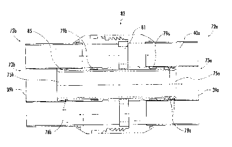
[0062] Turning now additionally to FIGS. 7-12, a
transmission line segment coupler or "bullet" 70 for coupling
together sections of a coaxial transmission line is now
described. More particularly, the transmission line may be
installed by coupling together a series of segments to grow
the length of the transmission line as the RF antenna is fed
deeper into the wellbore. Typical transmission line segments
may be about twenty to forty feet in length, but other segment
lengths may be used in different embodiments. The bullet 70
may be particularly useful for coupling together transmission
line segments which define a cooling fluid circuit, as will be
appreciated by those skilled in the art However, in some
embodiments a linear bearing configuration similar to the one
illustrated herein may be used to couple liquid timing
sections or baluns, such as those described above.
[0063] The bullet 70 is configured to couple first and
second coaxial transmission line segments 72a, 72b, each of
which includes an inner tubular conductor 39a and an outer
tubular conductor 40a surrounding the inner tubular conductor,
as described above, and a dielectric therebetween. The bullet
70 includes an outer tubular bearing body 71 to be positioned
within adjacent open ends 73a, 73b of the inner tubular
conductors 39a, 39b of the first and second coaxial
transmission line segments 72a, 72b, and an inner tubular
21
CA 02842425 2014-02-06
bearing body 74 configured to slidably move within the outer
tubular bearing body to define a linear bearing therewith. The
inner tubular bearing body 74 is configured to define a fluid
passageway in communication with the adjacent open ends 73a,
73b of the inner tubular conductors 39a, 39b of the first and
second coaxial transmission line segments 72a, 72b.
[0064] More particularly, the inner tubular bearing body 74
includes opposing first and second ends 75a, 76b extending
outwardly from the outer tubular bearing 71, and a medial
portion 76 extending between the opposing first and second
ends. The medial portion 76 of the inner tubular bearing body
74 has a length greater than the outer tubular bearing body 71
to define a linear bearing travel limit, which is defined by a
gap 77 between the outer tubular bearing 71 and the second end
76b (see FIG. 10). More particularly, the gap 77 allows linear
sliding play to accommodate section thermal expansion. By way
of example, a gap 77 distance of about inch will generally
provide adequate play for the operating temperatures (e.g.,
approximately 150 C internal, 20 C external at typical
wellbore depths) and pressure levels (e.g., about 200 to 1200
PSI internal) experienced in a typical hydrocarbon heating
implementation, although other gap distances may be used.
[0065] The bullet 70 further includes one or more
respective sealing rings 78a, 78b (e.g., 0-rings) carried on
each of the first and second ends 75a, 76b. Furthermore, the
first end 75a and the medial portion 76 may be threadably
coupled together. In this regard, hole features 84 may be
provided for torque-tool gripping, if desired. Also, the first
end 75a is configured to be slidably received within the open
end 73a of the tubular inner conductor 39a of the first
coaxial transmission line segment 72a, and the second end 75b
is configured to be fixed to the open end 73b of the tubular
inner conductor 39b of the second coaxial transmission line
22
CA 02842425 2014-02-06
segment 73b. More particularly, the second end 75b may have a
crimping groove 84 therein in which the open end 73b of the
tubular inner conductor 39b is crimped to provide a secure
connection therebetween.
[0066] The bullet 70 further includes a respective
electrically conductive spring 79a, 79b carried on each end of
the outer tubular bearing body 71. The springs 79a, 79b are
configured to engage a respective open end 73a, 73b of the
respective inner tubular conductor 39a, 39b of the first and
second coaxial transmission line segments 72a, 72b. More
particularly, the outer tubular bearing body 71 may have a
respective annular spring-receiving channel 80a, 80b on an
outer surface thereof for each electrically conductive spring
39a, 39b. The illustrated springs 79a, 79b are of a
"watchband-spring" ring type, which advantageously provide
continuous electrical contact from the inner conductor 39a
through the inner tubular bearing body 71 to the inner
conductor 39b. However, other spring configurations (e.g., a
"spring-finger" configuration) or electrical contacts biasable
by a flexible member (e.g., a flexible 0-ring, etc.) may also
be used in different embodiments.
[0067] To provide enhanced electrical conductivity, the
springs 79a, 79b may comprise beryllium, which also helps
accommodate thermal expansion, although other suitable
materials may also be used in different embodiments. The inner
tubular bearing body 74 may comprise brass, for example, to
provide enhanced current flow and wear resistance, for
example, although other suitable materials may also be used in
different embodiments. The first end 75a (or other portions of
the inner tubular bearing body 74) may also be coated with
nickel, gold, etc., if desired to provide enhanced
performance. Similarly, the outer tubular bearing body 71 may
also comprise brass, and may be coated as well with gold,
23
CA 02842425 2014-02-06
etc., if desired. Here again, other suitable materials may be
used in different embodiments.
[0068] The bullet 70 further includes a dielectric support
81 for the outer tubular bearing body 71 within a joint 82
defined between adjacent tubular outer conductors 40a, 40b of
the first and second coaxial transmission line segments 72a,
72b. In addition, the dielectric support 81 may have one or
more fluid passageways 83 therethrough to permit passage of a
dielectric cooling fluid, for example, as described above. As
seen in FIG. 10, the dielectric support 81 sits or rests in a
corresponding groove formed in the outer tubular bearing body
71.
[0069] As a result of the above-described structure, the
bullet 70 advantageously provides a multi-function RE'
transmission line coaxial inner-coupler, which allows for
dielectric fluid transport and isolation as well as
differences in thermal expansion between the inner conductor
39 and the outer conductor 40. More particularly, while some
coaxial inner couplers allow for some fluid transfer between
different segments, such couplers generally do not provide for
coefficient of thermal expansion (CTE) mismatch accommodation.
This may become particularly problematic where the inner
conductor 39 and the outer conductor 40 have different
material compositions with different CTEs, and the
transmission line is deployed in a high heat environment, such
as a hydrocarbon resource heating application. For example, in
a typical coaxial transmission line, the inner conductor 39
may comprise copper, while the outer conductor 40 comprises a
different conductor, such as aluminum.
[0070] As shown in FIG. 9, the bullet 70 advantageously
allows various flow options, including internal flow in one
direction, with an external return flow in the opposite
direction through the annulus at the well head. Moreover, as
24
CA 02842425 2014-02-06
shown in FIG. 10, the sealed, uniform, and streamlined
internal surface of the inner tubular bearing body 74 allows
for flow with relatively small interruption.
[0071] A related method for making the bullet 70 is now
briefly described. The method includes forming the outer
tubular bearing body 71, forming the inner tubular bearing
body 74 which is configured to slidably move within the outer
tubular bearing body to define a linear bearing therewith, and
positioning the inner tubular bearing body within the outer
tubular bearing body. More particularly, the second end 75b
may be crimped to the inner conductor 39b of a coaxial
transmission line segment at the factory, and the outer
tubular bearing body 74 positioned on the inner tubular
bearing body 71. The first end 75a is then screwed on to (or
otherwise attached) to the medial portion 76 to secure the
assembled bullet 70 to the coaxial transmission line segment
72b. The completed assembly may then be shipped to the well
site, where it is coupled end-to-end with other similar
segments to define the transmission line 38 to be fed down
into the wellbore 33.
[0072] Turning now additionally to FIGS. 13 and 16, another
advantageous approach to provide additional RF tuning (or
independent RF tuning) based upon the cooling fluid
circulating through the transmission line 38 is now described.
By way of background, in order to heat surrounding media and
more easily facilitate extraction of a hydrocarbon resource
(e.g., petroleum), a relatively high-power antenna is deployed
underground in proximity to the hydrocarbon resource 31, as
noted above. As the geological formation is heated, its
complex electrical permittivity changes with time, which means
the input impedance of the RF antenna 35 used to heat the
formation also changes with time. To efficiently deliver
energy from the RF antenna 35 to the surrounding medium, the
CA 02842425 2014-02-06
characteristic impedance of the transmission line 38 should
closely match the input impedance of the RF antenna.
[0073] In accordance with the present embodiment, relative
electric permittivity of circulating dielectric fluids used to
cool the transmission line 38 may be tailored or adjusted such
that the characteristic impedance of the coaxial transmission
line more closely matches the input impedance of the RF
antenna 35 as it changes with time. This approach may be
particularly beneficial in that the transmission line 38 and
the RF antenna 35 are generally considered inaccessible once
deployed in the wellbore 33. Moreover, impedance matching
units using discrete circuit elements may be difficult to
implement in a wellbore application because of low frequencies
and high power levels. Further, while the frequency of the RF
signal may be varied to change the imaginary part of the input
impedance (i.e., reactance), this does little to help better
match the real part (i.e., resistance) of the input impedance
to the characteristic impedance of the transmission line 38.
[0074] Accordingly, a liquid coolant source 129 is
advantageously configured to be coupled to the transmission
line 38 and to provide a liquid coolant through the liquid
coolant circuit having an electrical parameter (e.g., a
dielectric constant) that is adjustable. The liquid coolant
source 129 includes a liquid pump 130 and a heat exchanger 133
coupled in fluid communication therewith. The pump 130
advantageously circulates the liquid coolant through the
liquid coolant circuit of the transmission line 138 and the
heat exchanger 133 to cool the transmission line so that it
may maintain desired operating characteristics, as noted
above. Various types of liquid heat exchanger arrangements may
be used, as will be appreciated by those skilled in the art.
[0075] Furthermore, the liquid coolant source 129 also
includes a plurality of liquid coolant reservoirs 132a, 132b
26
CA 02842425 2014-02-06
each for a respective different liquid coolant. Dielectric
liquid coolants such as those described above (e.g., mineral
oil, silicon oil, etc.) may be used. More particularly, each
liquid cooling fluid may have different values of the
electrical parameter. Furthermore, a mixer 131 is coupled with
the pump 130 and the liquid coolant reservoirs 132a, 132b for
adjustably mixing the different liquid coolants to adjust the
electrical parameter. The liquid coolants may be miscible in
some embodiments. That is, a mixture of two or more miscible
dielectric fluids having different dielectric constants may be
mixed to provide continuous impedance matching to the changing
RF antenna 35 impedance.
[0076] In some embodiments, a controller 134 may be coupled
to the mixer 131 (as well as the pump 130), which is used to
the control the coolant fluid mixing based upon a changing
impedance of the transmission line 38. That is, the controller
134 is configured to measure an impedance of the transmission
line 38 and RF antenna as they change over the course of the
heating cycle, and change the cooling fluid mixture
accordingly to provide the appropriate electrical parameter to
change the impedance for enhanced efficiencies. In some
embodiments, the controller 134 may optionally include a
communications interface 135 configured to provide remote
access via a communications network (e.g., cellular, Internet,
etc.). This may advantageously allow for remote monitoring and
changing of the coolant fluid mixture, which may be
particularly advantageous for remote installations that are
difficult to reach. Moreover, this may also allow for remote
monitoring of other operational parameters of the well,
including pressure, temperature, available fluid levels, etc.,
in addition to RF operating characteristics.
[0077] In particular, the characteristic impedance of the
coaxial transmission line 38 may be changed by varying the
27
CA 02842425 2014-02-06
dielectric constant of the cooling fluid used inside the
transmission line. The dielectric constant of the fluids may
be changed in discrete steps, using readily available fluids,
or in a continuous manner by deploying custom fluids with
arbitrary dielectric constants. Typical values of dielectric
constant range from about Er = 2 to 5, and more particularly
about 2.1 to 4.5, which may result in characteristic
impedances from about 15 ohms to 30 Ohms, given the typical
wellbore dimensions noted above. More specifically, for a
coaxial transmission line having an inner conductor with a
diameter d and an outer conductor with a diameter D, with the
inner conductor filled with a fluid of a given Er, the
characteristic impedance Zo of the coaxial transmission line is
as follows:
1ITID 1389
Zo = ¨ Pe; __ log10 27 c vri; d
[0078] Accordingly, the above-described approach may
advantageously provide for reduced RF signal loss, and
therefore higher efficiency to the overall system. This
approach may also provide for a relatively high voltage
breakdown enhancement inside both the RF antenna 35 and the
coaxial transmission line 38. In addition, the coolant mixture
may also provide pressure balance to thereby allow the RF
antenna 35 to be maintained at the given subterranean
pressure. The dielectric cooling fluid mixture also provides a
cooling path to cool the transmission line 38, and optionally
to the RF antenna 35 and the transducer casing (if used).
[0079] A related method for heating a hydrocarbon resource
in a subterranean formation having a wellbore extending
therein is now described with reference to FIG. 16. Beginning
28
CA 02842425 2014-02-06
at Block 121, the method includes coupling an RF transmission
line to an RF antenna and positioning the RF transmission line
and RF antenna within the wellbore, at Block 122, where the RF
transmission line defines a liquid coolant circuit
therethrough. The method further includes supplying an RF
signal to the transmission lined from an RF source, and
circulating a liquid coolant having an electrical parameter
that is adjustable from a liquid coolant source through the
liquid coolant circuit, at Blocks 123 and 124. As additional
tuning is required, the electrical parameter of the liquid
coolant may be adjusted appropriately (Blocks 125-126), as
discussed further above, which concludes the method
illustrated in FIG. 16 (Block 127).
[0080] It should be noted that the electrical parameter of
a dielectric fluid used in the above-described liquid balun 45
or liquid tuning sections 60 may similarly be changed or
adjusted to advantageously change the operating
characteristics of the liquid balun or liquid tuning sections.
That is, varying the dielectric properties of the fluids is
another approach to tuning the center frequency of the liquid
balun 45 or the liquid tuning sections 60. Moreover,
dielectric fluids with different electrical parameters may be
used in different components (e.g., cooling circuit fluid,
balun fluid, or tuning segment fluid).
[0081] Many modifications and other embodiments of the
invention will come to the mind of one skilled in the art
having the benefit of the teachings presented in the foregoing
descriptions and the associated drawings. Therefore, it is
understood that the invention is not to be limited to the
specific embodiments disclosed, and that modifications and
embodiments are intended to be included within the scope of
the appended claims.
29