Note: Descriptions are shown in the official language in which they were submitted.
- 1 -
SNOWMOBILE SUSPENSION
CROSS-REFERENCE
[0001] The present application claims priority to United States
Provisional
Patent Application No. 61/600,291, filed February 17, 2012 and United States
Provisional Patent Application No. 61/511,263, filed July 25, 2011.
TECHNICAL FIELD
[0002] The present invention relates to suspension assemblies for
tracked
vehicles, and more particularly to rear suspension assemblies for snowmobiles.
BACKGROUND
[0003] Irregularities in the terrain over which a tracked vehicle (such as
a
snowmobile) travels produce displacements and deflections of its suspension
assembly. A conventional suspension supports an endless track, which is
tensioned to
surround a pair of parallel slide rails, a plurality of idler wheels and at
least one drive
wheel or sprocket. A shock absorbing mechanism involving springs, hydraulic
dampers, and/or other shock absorbing elements, urges the slide frame assembly
and
the chassis (also known as a frame) of the tracked vehicle apart, against the
weight
supported above the suspension in a static condition.
[0004] When an irregularity such as a bump occurs on the terrain, the
suspension allows the slide rails to move toward the tunnel. Similarly, when a
depression occurs on the terrain, the suspension allows the slide rails to
move away
from the tunnel. In some cases, the terrain provides configurations for which
the
current tracked vehicles (and snowmobiles in particular) cannot or can only
minimally
accommodate. This is the case, for example, when the tracked vehicle is side-
billing.
A tracked vehicle is said to be side-hilling when it is positioned at least
partially
sideways on a slope. In such a position, an uphill part of the suspension is
disposed
vertically above a downhill part of the suspension. This can increase the
resistance to
lean the tracked vehicle into the slope to keep the tracked vehicle
horizontal..
I FGAL_1:24079329 1
CA 2842892 2018-03-22
CA 02842892 2014-01-22
WO 2013/016128 - 2 -
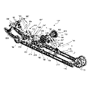
PCMJS2012/047374
[0005] Therefore, there is a need for a suspension assembly for a
tracked
vehicle that allows the tracked vehicle to drive on different terrain
configurations.
There is also a need for a tracked vehicle having such a suspension.
SUMMARY
[0006] One object of the present is to ameliorate at least some of the
inconveniences of the prior art.
[0007] In one aspect of the present, a suspension assembly for a
tracked
vehicle is provided. The suspension assembly has a chassis and an endless
drive track.
The suspension assembly has a longitudinal direction and a lateral direction.
The
suspension assembly comprises a rail adapted for engagement with the endless
drive
track. The rail is extending in the longitudinal direction. A first suspension
arm has an
upper end and a lower end. The upper end of the first suspension arm is
adapted for
pivotally connecting to the chassis about a first lateral axis. The lower end
of the first
suspension arm is pivotally connected to the rail about a second lateral axis.
The first
suspension arm is extending forwardly and upwardly from the rail. A second
suspension arm is disposed rearwardly of the first suspension arm. The second
suspension arm has an upper end and a lower end. The upper end of the second
suspension arm is adapted for pivotally connecting to the chassis about a
third lateral
axis. The lower end of the second suspension arm is pivotally connected to the
rail
about a fourth lateral axis. The second suspension arm is extending forwardly
and
upwardly from the rail. At least one shock absorber is connected between the
chassis
and the rail for biasing the rail away from the chassis. At least a portion of
at least one
of the first and second suspension arms is pivotable about a longitudinally
extending
axis relative to the rail.
[0008] In a further aspect, at least one ball joint is pivotally connecting
the at
least one of the first and second suspension arms to the rail.
[0009] In an additional aspect, the at least one of the first and
second
suspension arms includes the second suspension arm. The lower end of the
second
suspension arm is pivotally connected to the rail about the longitudinally
extending
axis.
CA 02842892 2014-01-22
WO 2013/016128 - 3 -
PCT/US2012/047374
[0010] In a further aspect, a rocker arm has an upper end and a lower
end. The
upper end of the rocker arm is pivotally connected to the lower end of the
second
suspension arm about a fifth lateral axis. The lower end of the rocker arm is
pivotally
connected to the rail about the fourth lateral axis.
[0011] In an additional aspect, a ball joint pivotally connects the lower
end of
the rocker arm to the rail about the fourth lateral axis and the
longitudinally extending
axis.
[0012] In a further aspect, a ball joint pivotally connects the lower
end of the
second suspension arm to the upper end the rocker arm about the fifth lateral
axis and
the longitudinally extending axis.
[0013] In an additional aspect, the at least one of the first and
second
suspension arms is pivotable about the longitudinally extending axis by a roll
angle.
The roll angle is between 0 and 10 degrees with respect to vertical.
[0014] In a further aspect, the roll angle is between 0 and 3 degrees
with
respect to vertical.
[0015] In an additional aspect, the at least one of the first and
second
suspension arms includes the first suspension arm and the second suspension
arm.
[0016] In a further aspect, a first ball joint is pivotally connecting
the lower
end of first suspension arm to the rail about the second lateral axis and the
longitudinally extending axis. A second ball joint is pivotally connecting the
lower
end of second suspension arm to the rail about the fourth lateral axis and the
longitudinally extending axis.
[0017] In another aspect of the present, a tracked vehicle is
provided. The
tracked vehicle comprises a chassis including a tunnel. An engine is connected
to the
chassis. An endless drive track is disposed below the tunnel and operatively
connected
to the engine for propulsion of the tracked vehicle. A suspension assembly is
supporting and tensioning the endless drive track. The suspension assembly has
a
longitudinal direction and a lateral direction. The suspension assembly
includes a rail
engaging the endless drive track. The rail is extending in the longitudinal
direction. A
CA 02842892 2014-01-22
WO 2013/016128 - 4 -
PCT/US2012/047374
suspension arm has an upper end and a lower end. The upper end of the
suspension
arm is pivotally connected to the chassis about a first lateral axis. The
lower end of the
suspension arm is pivotally connected to the rail about a second lateral axis.
At least
one shock absorber is connected between the chassis and the rail for biasing
the rail
away from the chassis. The chassis is pivotally connected to the rail via the
suspension assembly about a longitudinally extending axis.
[0018] In a further aspect, the lower end of the suspension arm is
pivotally
connected to the rail about the longitudinally extending axis.
[0019] In an additional aspect, a ball joint is pivotally connecting
the lower
end of the suspension arm to the rail.
[0020] In a further aspect, a rocker arm has an upper end and a lower
end. The
upper end of the rocker arm is pivotally connected to the lower end of the
suspension
arm about a third lateral axis. The lower end of the rocker arm is pivotally
connected
to the rail about the second lateral axis.
[0021] In an additional aspect, the ball joint pivotally connects the lower
end
of the rocker arm to the rail about the second lateral axis and the
longitudinally
extending axis.
[0022] In a further aspect, the ball joint pivotally connects the
lower end of the
suspension arm to the upper end the rocker arm about the third lateral axis
and the
longitudinally extending axis.
[0023] In an additional aspect, the lower end of the suspension arm is
pivotable about the longitudinally extending axis by a roll angle. The roll
angle is
between 0 and 10 degrees with respect to vertical.
[0024] In a further aspect, the roll angle is between 0 and 3 degrees
with
respect to vertical.
[0025] In an additional aspect, the tracked vehicle is a snowmobile.
The
suspension assembly is a rear suspension assembly. At least one ski is
operatively
connected to the chassis by a front suspension.
PCT/US 12/47374 27-05-2013
PCT/US2012/047374 22.08.2013
CA 02842892 2014-01-22
[00261 in 'yet another aspect of the present, a snowmobile
is provided. The
snowmobile comprises a chassis including a tunnel. The tunnel low a
longitudinal
direction. An engine is connected to the chassis. At least one ski is
connected to the
chassis by a -front SW-Tension: An endless drive track is disposed below the
tunnel and
is operatively connected to the. engine for propulsion of the snowmobile. A
rear
=
Suspension assembly is supporting .and tensioning the endless drive track. The
chassis
is pivotally connected to the endless drive track via the rear suspension
assembly
=
about a longitudinally extending axis.
=
[00271 For purposes of this application, terms related to
spatial orientation
JO such as forwardly, reatwardly, upwardly, downwardly, left, and right,
are as they
Would normally be understood by a driver of the vehicle sitting thereon in a
normal
riding position. Terms related to spatial orientation when describing or
referring to
components or sub-assemblies of the vehicle, separately from the vehicle, such
as the
tunnel or the suspension assemblies for example, should be understood as they
would
=
be understood when these components or sub-assemblies are mounted to the
vehicle.
=
= [00281 Embodiments of the present invention each
have at least one of the
above-mentioned object and/or aspects, but do not necessarily have all of
them. It .
should he understood that some aspects of the present invention that have
resulted
from attempting to attain the above-mentioned objects may not satisfy these
objects
=
2.0 and/or may satisfy other Objects not specifically recited herein.
=
[00291 Additional and/or alternative features, aspects, and
advantages of
= embodiments of the present invention will become
apparent from the following
=
= description, the accompanying drawings, and the appended claims.
BRIEF DESCRIPTION OF THE DRAWINGS
100301 For a better understanding of the present invention, as well as
other
aspects and titrther features thereof, reference is made to the following
description
which is to be used in cunjunction with the accompanying drawings, where:
=
= 100311 Fig. 1 is a left side elevation view of a
snowmobile;
if
=
AMENDED SHEET - IPEA/US
=
CA 02842892 2014-01-22
WO 2013/016128 - 6 -
PCT/US2012/047374
[0032] Fig. 2 is a perspective view taken from a rear, left side of a
first
embodiment of a suspension assembly of the snowmobile of Fig. 1;
[0033] Fig. 3 is a cross-sectional view of a portion of the suspension
assembly
of Fig. 2 taken along line 3-3 of the suspension assembly of Fig. 2;
[0034] Fig. 4 is a perspective view taken from a rear, left side of a front
suspension arm of the front suspension assembly of Fig. 2;
[0035] Fig. 5 is a lateral cross-section of a portion of the
snowmobile of Fig. 1
having the suspension assembly of Fig. 2 shown while side-hilling;
[0036] Fig. 6 is a perspective view taken from a rear, left side of a
second
embodiment of a suspension assembly of the snowmobile of Fig. 1;
[0037] Fig. 7 is a schematic lateral cross-section of a portion of the
snowmobile of Fig. 1 having the suspension assembly of Fig. 6 shown while side-
hilling;
[0038] Fig. 8 is a perspective view taken from a rear, left side of a
third
embodiment of a suspension assembly of the snowmobile of Fig. 1; and
[0039] Fig. 9 is left side elevation view of the suspension assembly
of Fig. 8.
DETAILED DESCRIPTION
[0040] Referring to Fig. 1, a snowmobile 100 will be described.
Although a
snowmobile is presented herein. It is contemplated that aspects of the present
could be
applied to other types of tracked vehicles.
[0041] The snowmobile 100 includes a front end 102 and a rear end 104,
which are defined consistently with the forward travel direction of the
vehicle. The
snowmobile 100 includes a chassis 106. The chassis 106 includes a tunnel 108,
an
engine cradle portion 110 and a front suspension assembly portion 112. An
engine
.. 114 which is schematically illustrated, is carried by the engine cradle
portion 110 of
the chassis 106. A ski and steering assembly is provided, in which two skis
116 (only
one of which is shown) are positioned at the front end 102 of the snowmobile
100,
and are attached to the front suspension assembly portion 112 of the chassis
106
CA 02842892 2014-01-22
WO 2013/016128 - 7 -
PCT/US2012/047374
through a front suspension assembly 118. The front suspension assembly 118
includes
ski legs 120, supporting arms 122 and ball joints for operatively joining the
respective
ski legs 120, supporting arms 122 and a steering column 124. The steering
column
124 is attached at its upper end to a steering device, in this case a
handlebar 126,
which is positioned forward of a rider and behind the engine 114 to rotate the
ski legs
120 and thus the skis 116, in order to steer the vehicle. It is contemplated
that the
snowmobile 100 could have only one ski 116.
[0042] An
endless drive track 128 is positioned at the rear end 104 of the
snowmobile 100 and is disposed under the tunnel 108. The endless drive track
128 is
operatively connected to the engine 114 through a belt transmission system 130
which
is schematically illustrated by broken lines. Thus, the endless drive track
128 is driven
to run about a rear suspension assembly 132 for propulsion of the snowmobile
100.
The rear suspension assembly 132 has a lateral direction 1 and a longitudinal
direction
2 (both shown in Fig. 2). The rear suspension assembly 132 will be described
in
greater detail below.
[0043] At the
front end 102 of the snowmobile 100, there are provided fairings
134 that enclose the engine 114 and the belt transmission system 130, thereby
providing an external shell that not only protects the engine 114 and the belt
transmission system 130, but also make the snowmobile 100 more aesthetically
pleasing. The fairings 134 include a hood and one or more side panels which
are all
openable to allow access to the engine 114 and the belt transmission system
130 when
this is required. Easy access may be required for example for inspection or
maintenance of the engine 114 and/or the belt transmission system 130. A
windshield
136 is connected to the fairings 134 near the front end 102 of the snowmobile
100, or
may be attached directly to the handlebar 126. The windshield 136 acts as a
windscreen to lessen the force of the air on the rider while the snowmobile
100 is
moving.
[0044] A seat
138 is connected to and disposed on the tunnel 108. A rear
portion of the seat 138 may include a storage compartment, or may be used to
accept a
passenger seat. Two foot rests 140 (only one of which is shown) are positioned
on
opposed sides of the snowmobile 100 below the seat 138 to accommodate the
rider's
feet.
CA 02842892 2014-01-22
WO 2013/016128 - 8 -
PCT/US2012/047374
[0045] The
endless drive track 128 is engaged with and driven by a drive
sprocket (not shown) which is joumaled by the tunnel 108 and is driven by the
engine
114 through the belt transmission system 130. The endless drive track 128 is
suspended for movement relative to the chassis 106, by the rear suspension
assembly
132, as will be described below.
[0046] The
snowmobile 100 includes other components which will not be
described in detail herein.
[0047] Referring
to Figs. 2 to 5, a first embodiment of the rear suspension
assembly 132 will now be described.
[0048] The rear suspension assembly 132 includes a slide frame assembly 144
which includes a pair of spaced apart slide rails 146 that engage the inner
side of the
endless drive track 128. The slide frame assembly 144 journals two idler
rollers 150.
In addition, further rollers 152 are carried by the tunnel 108 and the slide
rails 146
(some of which have been omitted in the Figures for clarity), in order to
define the
path over which the endless drive track 128 travels.
[0049] As can be
seen in Fig. 4, a front suspension arm 155 includes two front
arms 154, a tube 183, and a tube 156. It is contemplated that the front
suspension arm
155 could have more or less elements than described above. For example, the
front
suspension arm 155 could have only one front arm 154.
[0050] As can be seen in Fig. 2, the front arms 154 extend downwardly and
rearwardly from a front portion of the tunnel 108. Upper ends of the front
arms 154
are pivotally attached to the tunnel 108 via the tube 183 so as to pivot about
a lateral
axis 16. The tube 183 is welded to the front arms 154 and extends
therebetween. The
lower ends of the front arms 154 are each pivotally attached to their
respective slide
rails 146 of the slide frame assembly 144 via the tube 156 so as to pivot
about a lateral
axis 17. The tube 156 is cut into two portions: a right portion 156a and a
left portion
156b. This reduces the torsional rigidity of the front suspension arm 155. The
movement of front portions of the slide rails 146 relative to the tunnel 108
of the
chassis 106 causes the front arms 154 to rotate relative to the tunnel 108
about a
lateral axis.
CA 02842892 2014-01-22
WO 2013/016128 - 9 -
PCT/US2012/047374
[0051] As best
seen in Fig. 4, the front arms 154 have an arm body 153 that
has flattened top and bottom surfaces, and ends 151 that have a cross-section
transitioning from a flattened cross-section of the arm body 153 to a round
cross-
section for connection to the tube 183 and tube 156. As a result, the front
arms 154
have a smaller moment of inertia near their centers than at their ends 151. It
is
contemplated that the front arms 154 could not have the flattened top and
bottom
surfaces. For example, the front arms 154 could have a generally circular
cross-
section throughout. The front arms 154 are made of metal tubes. It is also
contemplated that the front arms 154 could be made of a material other than
metal.
[0052] The rear suspension arm 165 includes two rear arms 164, a tube 166
and a bracket 190. It is contemplated that the rear suspension arm 165 could
have
more or less elements than described above. For example, the rear suspension
arm 165
could have only one rear arm 164.
[0053] The rear
arms 164 extend downwardly and reamardly from a rear
portion of the tunnel 108, and are disposed rearward of the front arms 154.
The rear
arms 164 are made of metal tubes of a general circular cross-section. It is
contemplated that the rear arms 164 could have other shapes of cross-section.
It is also
contemplated that the rear arms 164 could be of a material other than metal.
The rear
arms 164 are pivotally attached to the tunnel 108 of the chassis 106 by means
of a
tube and shaft assembly. The tube and shaft assembly includes the tube 166
rotatably
supported by a shaft 168 which is mounted at the opposite ends thereof to the
tunnel
108. The shaft 168 supports the rollers 152 supporting an upper portion of the
endless
drive track 128. Upper ends of the rear arms 164 are welded to the tube 166,
so that
the rear arms 164 are adapted to pivot about the shaft 168. The upper ends of
the rear
arms 164 pivot relative to the tunnel 108 about a lateral axis 18.
[0054] Lower
ends of the rear arms 164 are welded together and are pivotally
connected to a rocker arm 174 by a ball joint 210. The rocker arm 174 is an
inverted
V-shaped member pivotally connected to the slide rails 146 by a hollow-cross
bar
172. The hollow cross bar 172 extends in the lateral direction 1 between the
slide rails
146 and define a lateral axis of rotation of the rocker arm 174. The ball
joint 210 will
be described below. It is contemplated that the lower ends of the rear arms
164 could
CA 02842892 2014-01-22
WO 2013/016128 - 10 -
PCT/US2012/047374
not be welded together and would be each pivotally connected a corresponding
rocker
arm.
[0055] A front shock absorber assembly 180 disposed between the tunnel
108
(via the tube 183) and the slide frame assembly 144 extends rearwardly and
downwardly from the front portion of the tunnel 108. The front shock absorber
assembly 180 is disposed partially forward of the front arms 154 and
completely
forward of the axis 17. A lower end of the first shock absorber assembly 180
is
disposed forwardly of the lower ends of the front arms 154. The front shock
absorber
assembly 180 is a damping unit which includes a hydraulic damper and a coil
spring
for absorbing the impact energy when impact forces are applied to the opposite
ends
of the damping unit. The coil spring biases the damping unit toward an
extended
position so that the hydraulic damper is in a position to absorb the impact
energies.
Since shock absorber assemblies of the type of the shock absorber assembly 180
are
well known in the art, it will not be further described herein. It is
contemplated that
the hydraulic damper and/or the coil spring could be omitted.
[0056] The front shock absorber assembly 180 is operatively attached
at an
upper end thereof to the tunnel 108 by a shaft and front bracket assembly
comprising
the tube 183 and two brackets 182. The two brackets 182 are fixedly connected
to the
tube 183 near a center of the tube 183. The upper end of the front shock
absorber
assembly 180 is pivotally connected to the brackets 182 about a lateral axis
19 such
that an axial force is applied to the upper end of the front shock absorber
assembly
180 when the front arms 154 move with respect to the tunnel 108. The
connection
between the upper end of the front shock absorber assembly 180 and the
brackets 182
provides some play between these parts such that the shock absorber assembly
180
can pivot (i.e. roll) slightly relative to the brackets 182 about a generally
longitudinal
axis.
[0057] The front shock absorber assembly 180 is pivotally connected to
a
lower end thereof to the slide frame assembly 144 via a shaft 184. A bearing
or
bushing (not shown) is disposed around the shaft 184 and inside an aperture
(not
.. shown) in the lower end of the front shock absorber assembly 180. The shaft
184 is
fixedly connected to the left and right slide rails 146, extending between
them in the
lateral direction 1. The front shock absorber assembly 180 is adapted to
rotate about
CA 02842892 2014-01-22
W02013/016128 - 11 -
PCT/US2012/047374
the shaft 184. The bearing or bushing provides some play between the shaft 184
and
the lower end of the front shock absorber assembly 180 such that the shaft 184
can
pivot (i.e. roll) slightly relative to the lower end of the front shock
absorber assembly
180 about a generally longitudinal axis. It is contemplated that the bearing
or bushing
could be replaced by a connector providing two or more degrees of freedom such
as a
ball joint for example. It is contemplated that the front shock absorber
assembly 180
could be connected to other parts of the snowmobile 100.
[0058] The rear
shock absorber 196 extends forwardly and downwardly from
the rear portion of the tunnel 108, and is disposed at least in part
rearwardly of the
front arms 154. The rear shock absorber 196, similar to the hydraulic damper
of the
front shock absorber assembly 180, is well known in the art, and therefore
will not be
described in detail. The rear shock absorber 196 is pivotally connected at its
upper end
to the tunnel 108 about a lateral axis 21 via the rear an upper portion 190a
(Fig. 3) of
the bracket 190 mounted on the tube 166 and the shaft 168 assembly of the rear
arms
164. The rear shock absorber 196 is pivotally connected at its lower end to
generally
L-shaped brackets 189. The L-shaped brackets 189 are pivotally connected to
brackets 191 (best seen in Fig. 4) that are fixedly connected to the right
portion 156a
of the tube 156. Two rods 192 are pivotally connected at their upper ends to a
lower
portion 190b (Fig. 3) of the bracket 190 and at their lower ends to the L-
shaped
brackets 189. The lower ends of the rods 192 and of the rear shock absorber
196 are
pivotally connected to the L-shaped brackets 189 about a common lateral pivot
axis.
The rear shock absorber 196 is disposed laterally between the rods 192.
[0059] The rear
bracket 190 is fixedly connected to the tube 166. As
mentioned above, the tube 166 is rotatable over the shaft 168. It is
contemplated that
the rear bracket 190 could be two rear brackets.
[0060] Left and
right torsion springs 200 are provided in order to push the
slide frame assembly 144 apart from the tunnel 108 of the chassis 106, and to
maintain the front and rear shock absorber assemblies 180, 196 substantially
in an
extended condition when no substantial loads are applied thereon. The left and
right
torsion springs 200 surround the tube 166 at each end thereof A first free end
201
(only one being shown in Fig. 2) of each of the torsion springs 200 abuts a
corresponding knob 169, and a second free end 202 of each of the torsion
springs 200
CA 02842892 2014-01-22
WO 2013/016128 - 12 -
PCT/US2012/047374
abuts the slide rails 146. The knob 169 can be rotated to adjust tension in
the torsion
springs 200.
[0061] Left and
right flexible tension straps 206 (only the left one being
shown) are attached at their upper ends to the tube 183, and are attached at
their lower
ends to the slide frame assembly 144 by means of a cross bar 208 which extends
between the slide rails 146 and is attached at its opposite ends to the front
ends of the
slide rails 146. The flexible tension straps 206 prevent the slide frame
assembly 144
from being pushed too far away from the tunnel 108.
[0062] Turning
now to Fig. 3, the ball joint 210 rotatably connecting the lower
ends of the rear arms 164 to the rocker arm 174 will be described in more
detail. The
ball joint 210 is a two degrees of freedom joint which allows the lower ends
of the
rear arms 164 to rotate about a lateral axis 4 (as illustrated by arrow 11)
and about a
longitudinally extending axis 3 (as illustrated by arrow 13). The
longitudinally
extending axis 3 passes through axes 4 and 17 (Fig. 2). Since the axis 17 is
fixed
relative to the slide rails 146 and the axis 4 moves relative to the slide
rails 146 as the
suspension assembly 132 is compressed and extended (due to the movement of
rocker
arm 174), the longitudinally extending axis 3 pivots about the axis 17 as the
suspension assembly 132 is compressed and extended. The ball joint 210 is a
standard ball joint and details of its structure will not be described herein.
[0063] Because the ball joint 210 allows the lower ends of the rear
suspension
arm 165 to rotate about the longitudinally extending axis 3, the rear
suspension
assembly 132 is allowed to roll generally about the longitudinally extending
axis 3.
The chassis 106 rolls relative to the drive track 128. This can occur for
example, when
side-hilling as shown in Fig. 5. When the snowmobile 100 is side-hilling, the
ball joint
210 allows the tunnel 108 to remain substantially horizontal, while the slide
rails 146
and the portion of the endless drive track 128 they abut (i.e. the ground
contacting
portion) pivot about the longitudinally extending axis 3 so as to be disposed
at an
angle with respect to the tunnel 108 in order to remain in contact with a
ground 20
having a moderate slope. When side-hilling, the wheels 150, 152 connected to
the
slide rails 146, the cross bars 172, 208, the shaft 184 and the rocker arm 174
also
pivot about the longitudinally extending axis 3 so as to be disposed at an
angle with
respect to the tunnel 108. Fig. 3 shows the ball joint 210 positioned such
that the
CA 02842892 2014-01-22
WO 2013/016128 - 13 -
PCT/US2012/047374
rocker arm 174 is at a roll angle 5 of 2 degrees with respect to a vertical
15. It is
contemplated that the roll angle 5 could be between 0 and 10 degrees with
respect to
the vertical 15. It is also contemplated that the roll angle 5 could be
between 0 and 3
degrees with respect to the vertical 15. It should be understood that should
the slope
of the ground be greater than the maximum roll angle 5 permitted by the ball
joint
210, that the tunnel 108 and the elements connected thereto also lean relative
to the
vertical. It should also be understood that suspension assembly 132 allows the
slide
rails 146, the portion of the endless drive track 128 they abut, the wheels
150, 152
connected to the slide rails 146, the cross bars 172, 208 and the rocker arm
174 to
remain generally parallel to the ground and permit the driver to cause the
tunnel 108
and at least the portions of the snowmobile 100 connected directly thereto to
roll
about the longitudinally extending axis 3 such as when leaning in a turn.
[0064] It is
contemplated that the lower ends of the rear suspension arm 165
could be pivotally connected to a rocker arm 174 by a joint other than a ball
joint. For
example, the lower ends of the rear arms 164 could be pivotally connected to a
rocker
arm 174 about a lateral axis and a longitudinally extending axis by a
universal joint.
In another example, the lower ends of the rear arms 164 are pivotally
connected to a
rocker arm 174 by two one degree of freedom joints (one for the lateral
direction 1
and one for the longitudinal direction 2) joined to each other in series. It
is
contemplated that the ball joint 210 could pivotally connect the rocker arm
174 to the
slide rails 146, and that the rear arms 164 could be pivotally connected to
the rocker
arm 174 only about the lateral axis 4. It is contemplated that the rocker arm
174 could
be omitted and the rear arms 164 could be pivotally connected directly to the
cross bar
172 by the ball joint 210, a universal joint or two one degree of freedom
joints joined
to each other in series. It is also contemplated that the rocker arm 174 could
be
replaced by two rocker arms, one for each of the rear arms 164. It is
contemplated that
the ball joint 210 could pivotally connect to another part of the rear arms
164. For
example, the ball joint 210 could pivotally connect the upper end of the rear
arms 164
to the tunnel 108. Alternatively, each rear arm 164 could be made of two
sections
pivotally connected to each other so as to permit pivoting about a
longitudinally
extending axis.
CA 02842892 2014-01-22
WO 2013/016128 - 14 -
PCT/US2012/047374
[0065] As
mentioned above, the front arms 154 have a variable cross-section.
The variable cross-section alone or when combined with the split tube 156,
allows the
front arms 154 to be flexible about the longitudinally extending axis 3 so as
to permit
rolling between the chassis 106 and the slide rails 146 when the rear
suspension arm
165 rolls. It is also contemplated that slight roll of a portion of the front
suspension
arm 155 relative to the tunnel 108 could be achieved by ways other than
modifying a
cross-section of the front arms 154.
[0066] Referring
now to Figs. 6 and 7, a second embodiment of a rear
suspension assembly, rear suspension assembly 132', will now be described.
Elements
common to both the rear suspension assembly 132 and the rear suspension
assembly
132' have been given the same reference numerals and will not be described in
greater detail again herein.
[0067] A front
suspension arm 155' includes two front arms 154', and a tube
183'. It is contemplated that the front suspension arm 155' could have more or
less
elements than described above.
[0068] The front
arms 154' extend downwardly and rearwardly from a front
portion of the tunnel 108. Upper ends of the front arms 154' are pivotally
connected
to the tunnel 108 in a manner similar as the one described above with respect
to the
front arms 154. Lower ends of the front arms 154' are welded to each other and
are
both pivotally connected by a front ball joint 212' to a shaft 167' extending
laterally
between the slide rails 146. The front ball joint 212' is similar to the ball
joint 210
described above. The front ball joint 212' allows the front suspension arm
155' to
rotate about a lateral axis 6 and the longitudinally extending axis 3'. The
longitudinally extending axis 3' passes through the lateral axis 6 and the
lateral axis 8
described below. It is contemplated that the lower ends of the front arms 154'
could
be pivotally connected the slide rails 146 by a joint other than a ball joint.
For
example, the lower ends of the front arms 154' could be pivotally connected to
the
slide rail 146 by a universal joint. In another example, the lower ends of the
front
arms 154' are pivotally connected to the slide rails 146 by two one degree of
freedom
joints (one for the lateral direction 1 and one for the longitudinal direction
2) joined to
each other in series. It is contemplated that the front ball joint 212' could
pivotally
connect to another part of the front suspension arm 155'. For example, the
front ball
CA 02842892 2014-01-22
WO 2013/016128 - 15 -
PCT/US2012/047374
joint 212' could pivotally connect the upper ends of the front arms 154' to
the tunnel
108.
[0069] The front
arms 154' are made of metal tubes. The front arms 154' have
a circular cross-section throughout. It is contemplated that the front arms
154' could
have a variable cross-section. It is also contemplated that the front arms
154' could
have other shapes of cross-section, and that the front arms 154' could be of a
material
other than metal.
[0070] The rear
shock absorber 196 is pivotally connected at its upper end to
an upper portion of a bracket 190'. The rear shock absorber 196 is pivotally
connected at its lower end to generally L-shaped brackets 189'. The L-shaped
brackets 189' are pivotally connected to brackets 191' that are fixedly
connected to
the arms 154'. The two rods 192 are pivotally connected at their upper ends to
a
lower portion of the bracket 190' and at their lower ends to the L-shaped
brackets
189'. The lower ends of the rods 192 and of the rear shock absorber 196 are
pivotally
connected to the L-shaped brackets 189' about a common lateral pivot axis.
[0071] A rear
suspension arm 165' includes a single rear arms 164', a tube
166' and a bracket 190'. It is contemplated that the rear suspension arm 165'
could
have more or less than described above. For example, the rear suspension arm
165'
could have two rear arms 164'.
[0072] The rear arm 164' extends downwardly and rearwardly from the rear
portion of the tunnel 108, and is disposed rearward of the front arms 154'.
The rear
arm 164' is made of bent sheet metal. It is contemplated that the rear arm
164' could
have a different shape, and that the rear arm 164' could be of a material
other than
metal. The upper end of the rear arm 164' is pivotally attached to the tunnel
108 in a
manner similar to the rear arms 164.
[0073] A lower
end of the rear arm 164' is pivotally connected to a rocker arm
174' about a lateral axis 10. The rocker arm 174' is a V-shaped member. The
rocker
arm 174' is pivotally connected to the slide rails 146 by a rear ball joint
210'. The rear
ball joint 210' is similar to the ball joint 210 described above. The rear
ball joint 210'
allows the rear suspension arm 165' to rotate about a lateral axis 8 and the
longitudinally extending axis 3'. Since the lateral axes 6 and 8 are fixed
relative to the
CA 02842892 2014-01-22
WO 2013/016128 - 16 -
PCT/US2012/047374
slide rails 146, the longitudinally extending axis 3' also remains fixed as
the
suspension assembly 132' is compressed and extended. It is contemplated that
the
lower end of the rocker arm 174' could be pivotally connected to the slide
rails 146 by
a joint other than a ball joint. For example, the lower end of the rocker arm
174' could
be pivotally connected to the slide rails 146 by a universal joint. In another
example,
the lower end of the rocker arm 174' is pivotally connected to the slide rails
146 by
two one degree of freedom joints joined to each other in series. It is
contemplated that
the rear ball joint 210' could pivotally connect the rear arm 164' to the
rocker arm
174', and that the rocker arm 174' could be pivotally connected to the slide
rails 146
only about the lateral axis 8. It is contemplated that the rocker arm 174'
could be
omitted and that the rear arm 164' could be pivotally connected directly to
the cross
bar 172 by the rear ball joint 210', a universal joint or two one degree of
freedom
joints joined to each other in series. It is contemplated that the rear ball
joint 210'
could pivotally connect to another part of the rear suspension arm 165'. For
example,
the rear ball joint 210' could pivotally connect the upper end of the rear arm
164' to
the tunnel 108. It is also contemplated that the rear ball joint 210' could be
omitted,
and that the rear suspension arm 165' may be adapted to compensate for a
rotation
about the longitudinally extending axis 3' induced by the front ball joint
210' by
bending for example. It is also contemplated that the ball joints 210', 212'
could be
different from each other.
[0074] The ball
joints 210' and 212' allow parts of the rear suspension
assembly 132' to roll with respect to the tunnel 108 at a roll angle 5 between
0 and 10
degrees with respect to a vertical. The ball joints 210' and 212' allow some
roll, and
the slide rails 146 may, for example, remain in contact with the ground 20
when the
snowmobile 100 is side-hilling on a hill having a moderate slope. This is
illustrated
for the ball joint 212' in Fig. 7. When side-hilling, the slide rails 146, the
portion of
the endless drive track 128 they abut (i.e. the ground contacting portion),
the wheels
150, 152 connected to the slide rails 146, the cross bars 172, 208 and the
shaft 184
pivot about the longitudinally extending axis 3' relative to the tunnel 108.
When side-
hitting, the front suspension arm 155', the rear suspension arm 165', the rear
shock
absorber 196 and the rods 192 do not pivot about the longitudinally extending
axis 3'
relative to the tunnel 108.
CA 02842892 2014-01-22
WO 2013/016128 - 17 -
PCT/US2012/047374
[0075] Referring now to Figs. 8 and 9, a third embodiment of a rear
suspension assembly, rear suspension assembly 132¨, will now be described.
Elements common to the rear suspension assembly 132, the rear suspension 132'
and
the rear suspension assembly 132" have been given the same reference numerals
and
will not be described in greater detail again herein.
[0076] The rear suspension assembly 132" has the front suspension arm
155'
and associated elements described above with respect to the rear suspension
assembly
132'. The rear suspension assembly 132" also has the rear suspension arm 165,
the
rocker arm 174 and associated elements described above with respect to the
rear
suspension assembly 132. The rear shock absorber 196 and the rods 192 are
connected at their upper ends to the bracket 190 and at their lower ends to
the brackets
189'.
[0077] In this embodiment, the front suspension arm 155' and the rear
suspension arm 165 can pivot relative to the slide rails 146 about a
longitudinally
extending axis 3". The longitudinally extending axis 3" passes through the
ball
joints 210, 212', the lateral axis 6 and the lateral axis 4. Since the axis 6
is fixed
relative to the slide rails 146 and the axis 4 moves relative to the slide
rails 146 as the
suspension assembly 132" is compressed and extended (due to the movement of
rocker arm 174), the longitudinally extending axis 3" pivots about the axis 6
as the
suspension assembly 132¨ is compressed and extended. As can be seen in Fig. 9,
when then suspension arms 155' and 165 are not pivoted relative to the slide
rails 146
about the longitudinally extending axis 3", a plane (corresponding to the line
labelled
3" in Fig. 9) containing the longitudinally extending axis 3" and the lateral
axes 4, 6,
passes through the wheels 150 and at least some of the wheels 152 connected to
the
slide rails 146.
[0078] The ball joints 210 and 212' allow parts of the rear suspension
assembly 132" to roll with respect to the tunnel 108 at a roll angle between 0
and 10
degrees with respect to a vertical. The ball joints 210 and 212' allow some
roll, and
the slide rails 146 may, for example, remain in contact with the ground 20
when the
snowmobile 100 is side-hilling on a hill having a moderate slope. When side-
hilling,
the slide rails 146, the portion of the endless drive track 128 they abut
(i.e. the ground
contacting portion), the wheels 150, 152 connected to the slide rails 146, the
cross
CA 02842892 2014-01-22
WO 2013/016128 - 18 -
PCT/US2012/047374
bars 172, 208, the shaft 184 and the rocker arm 174 pivot about the
longitudinally
extending axis 3" relative to the tumid l 108. When side-hilling, the front
suspension
arm 155', the rear suspension arm 165, the rear shock absorber 196 and the
rods 192
do not pivot about the longitudinally extending axis 3" relative to the tunnel
108.
100791 Modifications and improvements to the above-described embodiments
of the present may become apparent to those skilled in the art. The foregoing
description is intended to be exemplary rather than limiting. The scope of the
present
is therefore intended to be limited solely by the scope of the appended
claims.