Note: Descriptions are shown in the official language in which they were submitted.
CA 02842947 2015-12-03
- File No. P1788PC00
WHEEL ASSEMBLY DEFINING A MOTOR/GENERATOR
BACKGROUND
(a) Field
[0001] The subject matter disclosed generally relates to vehicles using
electric
motors.
[0002] More particularly, the subject matter relates to an electric motor
embedded in a wheel.
(b) Related Prior Art
[0003] Internal combustion engines, particularly those of the reciprocating
piston type, currently propel most vehicles. Such engines are relatively
efficient,
compact, lightweight, and inexpensive mechanisms by which to convert highly
concentrated energy in the form of fuel into useful mechanical power. The
primary problem with conventional gasoline or diesel combustion engines is
that they require fossil fuels that are not renewable and contribute to
pollution.
Consequently, a fuel that is renewable and does not contribute to pollution is
desirable.
[0004] One alternative to combustion vehicles is hybrid vehicles. Hybrid
vehicles include an electrical power source in addition to the internal
combustion engine. In particular, the hybrid vehicle may include a gasoline
engine, fuel tank, electric motor, batteries, transmission, and electric
generator.
Various approaches to combining the electrical power source and the internal
combustion engine are known, such as a parallel hybrid in which the engine
and electric motor can both simultaneously drive the transmission and the
series hybrid in
1
CA 02842947 2014-01-10
WO 2013/006962 PCT/CA2012/000673
which the engine drives the electric generator which charges the batteries or
powers the electric motor to drive the transmission.
[0005] Some hybrid vehicles are configured to allow connecting the
vehicle to an external electric power supply, that is, the hybrid vehicle may
be
plugged in for charging. There are also battery electric vehicles that are
fully
powered by the electrical power source. The battery electric vehicle is
configured
to allow connecting the vehicle to an external power supply, that is, the
battery
electric vehicle may be plugged in for charging.
[0006] Each of the above vehicles use a central engine/motor and
requires
a transmission in order to transmit the rotation power from the engine/motor
to
the wheels.
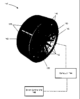
[0007] A typical mechanical transmission for fuel powered vehicles
allows
some freedom in engine operation, usually through alternate selection of five
or
six different drive ratios, a neutral selection that allows the engine to
operate
accessories with the vehicle stationary, and clutches or a torque converter
for
smooth transitions between driving ratios and to start the vehicle from rest
with
the engine turning. Transmission gear selection typically allows power from
the
engine to be delivered to the rest of the drive system with a ratio of torque
multiplication and speed reduction.
[0008] No transmission system is ever completely efficient and there is
always a percentage of energy lost in friction in the axle, gearing, clutch
and the
like, especially when the vehicle is equipped with an all wheel traction
mechanism (AWD).
[0009] Another problem associated with conventional vehicles is that
substantial amount of the car's weight and storage space is taken for the
engine/motor and the transmission system, not to mention the maintenance and
replacement parts which are provided in large numbers in each vehicle.
2
CA 02842947 2014-01-10
WO 2013/006962 PCT/CA2012/000673
[0010] Therefore there is a need for vehicle traction system which is
independent of conventional transmission systems.
SUMMARY
[0011] According to an aspect, there is provided a vehicle comprising:
- a chassis;
- a power source;
- at least one wheel assembly attached to the chassis, the wheel assembly
comprising:
O two or more wheel shaped stator units, each stator unit may be
having a plurality of spokes co-centrically provided around a
hub/shaft, the hub/shaft being attached to chassis of the vehicle;
O a coil wrapped around at least some of the spokes for generating a
magnetic field;
O a wheel shaped rotor adapted to receive the stator units therein, the
rotor may be rotatably attached to the hub/shaft and comprising a
plurality of magnets provided on an inner periphery of the rotor facing
the spokes, wherein the magnets are arranged so that adjacent
magnet poles have opposite magnetic polarities;
- a driver control unit for receiving driving commands;
- a computer operably connected to the driver control unit for controlling
an
intensity of an electric current fed into the coils in accordance with the
driving commands, the computer may be adapted to control operation of
the coils to selectively activate idle coils and deactivate activated coils to
avoid overheating;
wherein interaction between magnetic fields generated by the coils and
magnetic
fields generated by the magnets cause the rotor to rotate around the stator..
3
CA 02842947 2014-01-10
WO 2013/006962 PCT/CA2012/000673
[0012] In an embodiment, the coils may be controlled on a stator unit
level,
and all coils of the same stator unit may be activated or deactivated
simultaneously to avoid overheating.
[0013] In another embodiment, each coil may be controlled separately,
and selected coils of different stator units may operate at the same time to
avoid
overheating.
[0014] In another embodiment, a space may exist between adjacent stator
units.
[0015] In another embodiment, the stator units may have different
magnetic capacities.
[0016] In another embodiment, the power source may include one or more
of: a battery, a solar panel, and a generator connected to a combustion
engine.
[0017] In another embodiment, a spacing may exist between the stator
and the magnets of the rotor.
[0018] In another embodiment, the magnets may be permanent magnets.
[0019] In another embodiment, the magnets may be made of rare earth
materials.
[0020] In another embodiment, the magnets may include neodymium
magnets.
[0021] According to another aspect there is provided a wheel assembly
for
connecting to a vehicle, the wheel assembly may be comprising:
- two or more wheel shaped stator units, each stator unit may be
having a plurality of spokes co-centrically provided around a
hub/shaft, the hub/shaft for attaching to a chassis of the vehicle;
- a coil wrapped around at least some of the spokes for generating a
magnetic field in response to an electric current fed in the coil;
4
CA 02842947 2014-01-10
WO 2013/006962 PCT/CA2012/000673
- a
wheel shaped rotor adapted to receive the stator units therein, the
rotor being rotatably attached to the hub/shaft and comprising a
plurality of magnets provided on an inner periphery of the rotor facing
the spokes, wherein the magnets are arranged so that adjacent
magnet poles have opposite magnetic polarities, whereby magnetic
fields generated by the coils and magnetic fields generated by the
magnets cause the rotor to rotate around the stator;
wherein each stator unit may include a separate electrical wiring for
activating
and deactivating selected stator units.
[0022] In
another embodiment, the coils in a single stator unit are wired
together so that the coils are activated or deactivated simultaneously.
[0023] In
another embodiment, the coils in a single stator unit may be
wired together so that the coils are activated or deactivated simultaneously.
[0024] In
another embodiment, each coil may have a separate wiring and
selected coils of different stator units may be operate at the same time.
[0025] In
another embodiment, a space may exist between adjacent stator
units.
[0026] In
another embodiment, the stator units may have different
magnetic capacities.
[0027] In
another embodiment, a space may exist between the stator and
the magnets of the rotor.
[0028] In
another embodiment, magnets may include one of: permanent
magnets, rare earth magnets, and neodymium magnets.
[0029]
According to another aspect there is provided a method for
generating electricity, the method comprising:
- installing two or more wheel shaped stator units co-axially in a wheel
shaped rotor adapted to receive the stator units therein, wherein each
CA 02842947 2014-01-10
WO 2013/006962 PCT/CA2012/000673
stator unit may have a plurality of spokes co-centrically provided around a
hub/shaft and a coil provided around at least a portion of the spokes, and
wherein the rotor comprises a plurality of magnets provided on an inner
periphery of the rotor facing the spokes, the magnets may be arranged so
that adjacent magnet poles have opposite magnetic polarities;
- wiring each stator unit separately;
- rotating the rotor around the stator to create an electric current in the
coil;
- collecting the electric current from a first stator unit;
switching the collection of electric current from a first set of coils to a
second set
of coils to avoid overheating in the first set of coils.
[0030] In an embodiment, rotating the rotor may comprise connecting the
rotor to one of windmill and hydro-electric turbine.
[0031] In another embodiment, rotating rotor may comprise performing an
electromagnetic breaking in a vehicle.
[0032] Features and advantages of the subject matter hereof will become
more apparent in light of the following detailed description of selected
embodiments, as illustrated in the accompanying figures. As will be realized,
the
subject matter disclosed and claimed is capable of modifications in various
respects, all without departing from the scope of the claims. Accordingly, the
drawings and the description are to be regarded as illustrative in nature, and
not
as restrictive and the full scope of the subject matter is set forth in the
claims.
BRIEF DESCRIPTION OF THE DRAWINGS
[0033] Further features and advantages of the present disclosure will
become apparent from the following detailed description, taken in combination
with the appended drawings, in which:
[0034] Figure 1 illustrates an example of a conventional electric motor
in
which the rotor rotates within the stator;
6
CA 02842947 2014-01-10
WO 2013/006962 PCT/CA2012/000673
[0035]
Figure 2 illustrates an exploded view of exemplary wheel assembly
in accordance with an embodiment;
[0036]
Figure 3 illustrates an embodiment a wheel assembly provided as a
drum which is attachable to the chassis of the vehicle on one side and to a
standard wheel on the other side;
[0037]
Figure 4 illustrates a wheel assembly comprising a rotor and a
plurality of stator units within the rotor, in accordance with another
embodiment;
[0038]
Figure 5 is a top view of the wheel assembly of Figure 4, showing
the plurality of stator units underneath the magnets;
[0039]
Figure 6 illustrates an example of a vehicle including at least one
wheel assembly in accordance with an embodiment;
[0040]
Figure 7 illustrates an embodiment a hydro-electric turbine in
accordance with an embodiment; and
[0041]
Figure 8 is a flowchart of a method for generating electricity using a
vehicle assembly in accordance with the embodiment of Figure 4.
[0042] It
will be noted that throughout the appended drawings, like
features are identified by like reference numerals.
DETAILED DESCRIPTION OF THE PREFERRED EMBODIMENTS
[0043] The
present document describes a wheel assembly defining a
motor/generator. The wheel assembly comprises a plurality of stator units
coaxially provided within a rotor. The stator units comprise a plurality of
spokes
co-centrically provided around a hub/shaft and a coil provided around at least
a
portion of the spokes for generating an electrical field. The rotor comprises
a
plurality of magnets provided on an inner periphery of the rotor facing the
spokes.
The rotor is rotatably attached to the hub/shaft of the stator for rotating
around
the stator units when the coils are activated. The coils and/or the stator
units may
be selectively activated and deactivated to avoid overheating.
7
CA 02842947 2014-01-10
WO 2013/006962 PCT/CA2012/000673
[0044] Conventional electric motors include a stator comprising a
plurality
of coils for generating an electromagnetic field, and a rotor coaxial with and
surrounded by the stator. Figure 1 illustrates an example of a conventional
electric motor in which the rotor rotates within the stator. As shown in
Figure 1,
the motor 100 includes a chassis 101, a stator 102 fixed to the chassis 101,
and
a rotor 104 that rotates within the stator 102. The rotor 104 includes a shaft
106
mounted to the chassis 101 of the motor by a bearing or the like, whereby,
when
the motor is turned on, the coils of the stator generate an electromagnetic
field
which causes the rotor 104 to rotate within the stator 102. The shaft 106 of
the
rotor may be connected to other mechanical parts that require rotation such as
pump, fan or the like. Due to their shapes and configurations, such motors
cannot be used to rotate a wheel without implicating a transmission system.
[0045] Embodiments of the invention describe a wheel assembly
comprising an electrical motor embedded therein, whereby, it is possible to
use
such wheel in a vehicle without a transmission. Figure 2 illustrates an
exploded
view of an exemplary wheel assembly in accordance with an embodiment. As
shown in Figure 2, the wheel assembly 110 comprises a wheel shaped stator
112 (aka stator unit 112) and a wheel shaped rotor 114. The rotor 114 and the
stator 112 are dimensioned so that the stator 112 may be co-axially received
within the rotor 114 and rotatably attached to the latter, whereby the rotor
114
may rotate around the stator 112 when the wheel assembly is in operation.
[0046] The stator 112 comprises a plurality of spokes 116 co-
centrically
provided around a shaft/hub 118. The hub 118 may be attached to the chassis of
the vehicle. As shown in Figure 2, an electromagnetic coil 117 is provided
around
each spoke/spoke 116 for creating a magnetic field across the exterior surface
120 of the stator 112.
[0047] Spacing may be provided between the stator 112 and the rotor 114
to avoid friction and heating.
8
CA 02842947 2014-01-10
WO 2013/006962 PCT/CA2012/000673
[0048] The rotor 114 comprises a rim 122 and optionally a rubber tire
124
around the rim 122. As shown in Figure 2, the rotor 114 comprises a plurality
of
magnets 126 (e.g. permanent magnets, rare earth magnets, neodymium
magnets) provided on the inner side thereof. In an embodiment, the magnets 126
are arranged beside each other so that adjacent magnet poles have opposite
polarities e.g. north, south, north, south, etc. as shown in Figure 2. The
rotor 114
may be rotatably connected to the stator 112 using a bearing or the like
whereby,
when the stator is installed within the rotor and an electric current is
provided in
the windings, a magnetic field is generated by the winding/coils 117 which
causes the rotor 114 to rotate around the stator 112, thereby moving the
vehicle
to which the stator 112 is attached.
[0049] Accordingly, in a wheel assembly 110 in accordance with the
present embodiments, the stator 112 is fixedly attached to a shaft 118 and/or
to
the chassis of the vehicle on which the wheel assembly 110 is to be mounted.
By
contrast, the rim 122/wheel 124 is rotatably connected to the shaft 17 using a
bearing or any similar arrangement. In operation, the different coils 117 of
the
stator 112 generate an electromagnetic field which pushes and/or pulls the
different magnets 126 on the inner side of the rotor 114 and cause the rotor
114
to rotate around the rotation shaft 118.
[0050] In another embodiment, the wheel assembly may be provided as a
drum which is attachable to the chassis of the vehicle on one side and to a
standard/existing wheel on the other side. An example of such arrangement is
shown in Figure 3. The embodiment of Figure 3 may be provided as a kit for
installing in vehicles while effecting minor modifications to the existing
structure
of the vehicle. Figure 3 illustrates a wheel assembly 130 including a drum
shaped
wheel 132, and a stator 112 having a plurality of coils 117. The wheel 132
includes magnets on the inner side thereof (not shown in Figure 3). The stator
112 is fixed to the chassis of the car. The rotor is embedded in the wheel 132
and is rotatably mounted to the shaft 118 using a bearing. The drum 132
includes
9
CA 02842947 2014-01-10
WO 2013/006962 PCT/CA2012/000673
a plurality of bolts 134 for attaching to a wheel (not shown), and one or more
cutouts for cooling the coils 117 through ventilation.
[0051] With prolonged use and/or harsh driving conditions the coils
experience overheating which lessens their durability and increase the risk of
fire
or damage to the vehicle. The present embodiments offer a solution to this
problem by providing a wheel assembly including a rotor and a plurality of
stator
units coaxially provided within the same rotor for selectively activating one
or
more stator units and deactivating other ones to cool them down. Such wheel
assembly may also provide for higher torque by adding more stators in line
when
higher power is needed. Figure 4 illustrates a wheel assembly comprising a
rotor
and a plurality of stator units within the rotor, in accordance with another
embodiment, and Figure 5 is a top view of the wheel assembly of Figure 4,
showing the plurality of stator units underneath the magnets.
[0052] As shown in Figure 4, the wheel assembly 140 comprises a
plurality of magnets 126 defining a rotor, and a plurality of stator units 112
provided coaxially within the rotor and attached to the same shaft 142.
Needless
to say, the width of the magnets 140 is chosen so as to encompass all the
stator
units 112, as shown in Figure 4.
[0053] As described above, each stator unit 112 comprises a plurality
of
coils, each coil being provided around a spoke 116, wherein the spokes are
provided around the rotation shaft. In the embodiment of Figure 4, the stator
units
112 are controlled separately, whereby it is possible to selectively activate
one
stator unit and deactivate the other to avoid overheating, or activate
additional
stator units to increase the power as the needs arise. Activation and de-
activation
of the stator units 112 may be done using a computer 144 and/or manually by
the
user using a driver control unit 148 when more power is needed.
[0054] The computer 144 may be adapted to periodically activate an idle
stator unit 112 and deactivate a working one. In an embodiment, one or more
CA 02842947 2014-01-10
WO 2013/006962 PCT/CA2012/000673
heat sensors 146 are provided on each stator unit 112 (and or the rotor) to
measure the temperature and send the sensor readings to the computer 144 to
monitor the temperature and control the function of the stator units 112 based
on
real-time temperature data rather than periodically. The stator units may be
spaced apart for increased cooling, as shown in Figure 4 and 5 (see spacing
150).
[0055] In an embodiment, the stator units may have different widths and
different capacities. For example, in a wheel assembly having three stator
units,
it is possible that the middle stator unit has twice the width and power of
the
exterior stator units e.g. 25% for the exterior unit, 50% for the middle unit,
and
25% for the interior unit.
[0056] While the embodiment discussed above describes the activation
and deactivation of stator units, it is also possible to perform the
activation and
deactivation on the coil level whereby it is possible to activate one or more
coils
in one stator unit and activate other coils in another stator unit, then
deactivate
some or all of the activated coils and activate others in the same stator unit
or in
another stator unit within the same wheel assembly. In which case, each coil
may
be separately controlled by the computer 144 to activate and deactivate the
coil
when needed.
[0057] Figure 6 illustrates an example of a vehicle including at least
one
wheel assembly, in accordance with the present embodiments. As shown in
Figure 6, a vehicle 170 comprises a set of wheels 172. At least one of these
wheels 172 comprising an electrical wheel assembly as described in the present
embodiments. Preferably, all four wheels comprise the electrical wheel
assembly
described herein. In another embodiment, only the rear or front wheels are
provided with the electrical wheel assembly described herein.
[0058] The vehicle 170 comprises an energy source 174 e.g. a battery,
solar panel, generator mounted couple to a combustion engine etc.. The battery
11
CA 02842947 2014-01-10
WO 2013/006962 PCT/CA2012/000673
may be charged by plugging into a power source in the wall or by a
generator/break system/solar panel or the like on board of the vehicle 170
using
known techniques. Examples of suitable batteries include lithium batteries,
lithium air batteries, lithium-ion batteries, acid batteries, etc. The wheels
172 do
not require a conventional transmission system to rotate, and may be
individually
controlled by a central computer 144 to accelerate and decelerate them by
varying the current intensity/voltage fed by the battery based on control
signals
received from the driver using the driver control unit 148, and by activating
and
deactivating the stator units provided in each wheel to increase power and
torque
or to avoid overheating of one of the stator units 112.
[0059] A vehicle in accordance with the present embodiments does not
require a transmission system, thus, the vehicle may be lightweight and may
have a larger storage capacity.
[0060] In another embodiment, the wheels may be used for generating
electricity. For example, the wheels 172 may be used for electromagnetic
breaking by converting the kinetic energy of the car into an electric current
which
may be used for charging the battery of the car. When a wire or any other
electrically conductive material moves across a magnetic field, an electric
current
occurs in the wire. In conventional generators, electricity is generated by
the
movement of a coil between the poles of a magnet. By contrast, in the present
embodiment, the coil of the stator 112 remains static and magnets 126 of the
rotor 114 turn around the coils causing electrons to flow in the coils
creating an
electrical current.
[0061] It should be noted that use of the wheel assemblies 110 and 140
for the generation of electricity is not limited to vehicles. The wheel
assembly
may also be used in hydro-electric turbines, and wind turbines for generating
energy from renewable sources. An example of a hydro-electric turbine is shown
in Figure 7. As shown in Figure 7, the hydroelectric turbine 40 comprises a
wheel
assembly as described above, and a plurality of blades 44 provided on the
outer
12
CA 02842947 2014-01-10
WO 2013/006962 PCT/CA2012/000673
surface of the wheel assembly for receiving the flow of water and rotating the
rotor 114 around the stator 112 of the turbine 40, thus creating a flow of
electron
in the coils and generating an electric current.
[0062] The wheel assembly may be used in a variety of different
applications including but not limited to windmills, electric pumps, cars,
motorcycles etc.
[0063] When using the wheel assembly 140 of Figure 4 for the generation
of electricity, it is possible to collect the electric current from the wiring
of a first
stator unit and then switch to a second stator unit to avoid overheating the
first
stator unit with prolonged use. The same principle applies to coils whereby it
is
possible to collect electric current from selected coils in one or more stator
units
and then switch to other coils to avoid overheating in the coils.
[0064] Figure 8 is a flowchart of a method for generating electricity
using a
vehicle assembly in accordance with the embodiment of Figure 4. As shown in
Figure 8, step 190 comprises 18.A method for generating electricity, the
method
comprises installing two or more wheel shaped stator units co-axially in a
wheel
shaped rotor adapted to receive the stator units therein, wherein each stator
unit
has a plurality of spokes co-centrically provided around a hub/shaft and a
coil
provided around at least a portion of the spokes, and wherein the rotor
comprises
a plurality of magnets provided on an inner periphery of the rotor facing the
spokes, the magnets being arranged so that adjacent magnet poles have
opposite magnetic polarities. Step 192 comprises wiring each stator unit
separately. Step 194 comprises rotating the rotor around the stator to create
an
electric current in the coil. Step 196 comprises collecting the electric
current from
a first stator unit. Step 198 comprises switching the collection of electric
current
from a first set of coils to a second set of coils to avoid overheating in the
first set
of coils.
13
CA 02842947 2014-01-10
WO 2013/006962 PCT/CA2012/000673
[0065] While preferred embodiments have been described above and
illustrated in the accompanying drawings, it will be evident to those skilled
in the
art that modifications may be made without departing from this disclosure.
Such
modifications are considered as possible variants comprised in the scope of
the
disclosure.
14