Language selection

Search

Patent 2843228 Summary

Third-party information liability

Some of the information on this Web page has been provided by external sources. The Government of Canada is not responsible for the accuracy, reliability or currency of the information supplied by external sources. Users wishing to rely upon this information should consult directly with the source of the information. Content provided by external sources is not subject to official languages, privacy and accessibility requirements.

Claims and Abstract availability

Any discrepancies in the text and image of the Claims and Abstract are due to differing posting times. Text of the Claims and Abstract are posted:

  • At the time the application is open to public inspection;
  • At the time of issue of the patent (grant).
(12) Patent: (11) CA 2843228
(54) English Title: FEEDTHROUGH INSULATOR
(54) French Title: ISOLATEUR DE TRAVERSEE
Status: Granted and Issued
Bibliographic Data
(51) International Patent Classification (IPC):
  • H01B 17/00 (2006.01)
  • G01R 15/14 (2006.01)
  • H01B 17/26 (2006.01)
(72) Inventors :
  • BAUER, ALBERTO (United States of America)
(73) Owners :
  • G & W ELECTRIC COMPANY
(71) Applicants :
  • G & W ELECTRIC COMPANY (United States of America)
(74) Agent: MARKS & CLERK
(74) Associate agent:
(45) Issued: 2020-10-06
(86) PCT Filing Date: 2012-07-25
(87) Open to Public Inspection: 2013-02-14
Examination requested: 2017-07-18
Availability of licence: N/A
Dedicated to the Public: N/A
(25) Language of filing: English

Patent Cooperation Treaty (PCT): Yes
(86) PCT Filing Number: PCT/IT2012/000231
(87) International Publication Number: IT2012000231
(85) National Entry: 2014-01-27

(30) Application Priority Data:
Application No. Country/Territory Date
61/574,565 (United States of America) 2011-08-05

Abstracts

English Abstract


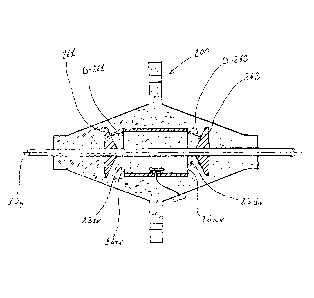
A feedthrough insulator is characterized by the fact to comprises: >-a central
rod (10) which extends longitudinally
with respect its longitudinal axis (10y); >-a sleeve (20) positioned coaxial
around said rod of connection (10) with the respective
circular shell (21) radially spaced (D-21) with respect to the central rod
(10); >-a sensor (30) of electric field and/or of magnetic field,
positioned in proximity of the inner surface (22) of said shell (21) of the
sieeve (20); and >-a carrying body (40) formed by dielectric
material able to contain and to embed said central rod (10), said sieeve (20)
and said sensor (30) of electrical field and/or of magnetic
field.


French Abstract

L'invention porte sur un isolateur de traversée, caractérisé en ce qu'il comprend : - une tige centrale (10) qui s'étend longitudinalement par rapport à son axe longitudinal (10y); - un manchon (20) positionné de façon coaxiale autour de ladite tige de connexion (10), l'enveloppe circulaire respective (21) étant radialement espacée (D-21) par rapport à la tige centrale (10); - un capteur (30) de champ électrique et/ou de champ magnétique positionné à proximité de la surface interne (22) de ladite enveloppe (21) du manchon (20); et - un corps de support (40) constitué par un matériau diélectrique apte à contenir et à incorporer ladite tige centrale (10), ledit manchon (20) et ledit capteur (30) de champ électrique et/ou de champ magnétique.

Claims

Note: Claims are shown in the official language in which they were submitted.


What is claimed is:
1. A feedthrough insulator comprising:
a central connecting rod extending along a longitudinal axis;
a cylindrical sleeve coaxial to and surrounding the connecting rod, wherein
the
sleeve is radially outwardly spaced from the connecting rod;
a sensor of electric or magnetic field positioned in proximity to an inner
surface of
the sleeve;
a dielectric support body containing and embedding the central rod, the sleeve
and
the sensor; and
at least one electrified screen element positioned near at least one of two
opposite
longitudinal open ends of the sleeve, at a reference potential, and positioned
to screen
entry of harmful-undesired electrical field lines generated by surrounding
conductors so
that the harmful-undesired electrical field lines do not impinge the sensor.
2. The feedthrough insulator according to claim 1, further comprising a
conductor
connecting the sensor with a device positioned on an external surface of the
support body.
3. The feedthrough insulator according to claim 1 or claim 2, wherein the
sleeve has a
longitudinal extension and the sensor is positioned in an intermediate point
with respect to
the longitudinal extension.
4. The feedthrough insulator according to any one of claims 1 to 3, wherein
the sleeve
has a longitudinal length configured to inhibit the harmful-undesired
electrical field lines
generated by surrounding the conductors from impinging on the sensor.
5. The feedthrough insulator according to any one of claims 1 to 4, wherein
the
sensor is electrically isolated from the sleeve.
6. The feedthrough insulator according to any one of claims 1 to 5, wherein
the at
least one screen element is mounted on the rod.
7. The feedthrough insulator according to claim 6, wherein the at least one
screen
element is longitudinally slidable and longitudinally adjustable on the rod.
8. The feedthrough insulator according to claim 7, wherein the rod
comprises an
external thread, the screen element comprises an internal thread, and the
external thread
- 6 -

and the internal thread fit together to allow longitudinal positioning of the
screen element
on the rod.
9. The feedthrough insulator according to any one of claims 1 to 8, wherein
the at
least one screen element is disk-shaped.
10. The feedthrough insulator according to claim 9, wherein the at least
one screen
element is spaced from the respective longitudinal end of the sleeve such that
a dielectric
strength of the dielectric support body is not exceeded.
11. The feedthrough insulator according to any one of claims 1 to 8,
wherein the at
least one screen element is frustoconical, and a smaller end of the at least
one screen
element is oriented toward a respective open end of the sleeve.
12. The feedthrough insulator according to claim 11, wherein the at least
one screen
element is spaced from the respective longitudinal end of the sleeve such that
a dielectric
strength of the dielectric body is not exceeded.
13. The feedthrough insulator according to any one of claims 1 to 8,
wherein the at
least one screen element is shaped as a funnel with a stem oriented toward an
opening of
the sleeve.
14. The feedthrough insulator according to claim 13, wherein sides of the
funnel have
a profile rounded in a convex manner with respect to the longitudinal axis of
the rod.
15. The feedthrough insulator according to claim 13, wherein sides of the
funnel
are rounded in a convex manner with respect to the longitudinal axis of the
rod with a
radius of curvature having a predetermined length corresponding to the minimum
spacing to be maintained between the circular perimeter of the sleeve with
respect to
the funnel such that the dielectric strength of the dielectric body is not
exceeded.
16. The feedthrough insulator according to claim 14 or claim 15, wherein
the
funnel is positioned next to a respective end of the sleeve and spaced with
respect to
the sleeve at a spacing equal to a length of the radius of the rounded sides
of the
funnel.
- 7 -

Description

Note: Descriptions are shown in the official language in which they were submitted.


Title
Feedthrough Insulator
*_ * _ * _ *
Technical Field
-The present invention concerns a feedthrough insulator for electrical
transformer tanks, electrical boxes, and other similar structures, in which
said
feedthrough insulator is able to sense the electrical field and/or the
magnetic
field generated by the live rod of connection of the same insulator, with the
purpose, for example, to determine the value of the voltage and/or the value
of
the current of the same live rod of connection in relationship with the fields
sensed.
-More in particular, the present invention concerns a feedthrough insulator of
the above type able to sense the electric field and/or the magnetic field
generated by the live rod of connection without being affected by any
surrounding electrical fields and/or magnetic fields, such as, for example,
the
electrical fields and/or the magnetic fields generated by other live
conductors
located nearby.
Backoround of the invention
-At the present the known feedthrough insulator are not able to sense the
electric field and/or the magnetic field generated by the live rod of
connection
and, besides, they are not able to sense the electric field and/or the
magnetic
field generated by the live rod of connection without being affected by the
surrounding electrical fields and/or magnetic fields generated by other live
conductors located nearby.
Summary
-The object of the present invention is to overcome the aforementioned
drawbacks.
-An aspect of the invention, which is defined in the claims, resolves the
problem of creating a feedthrough insulator comprising: a central rod of
connection which extends along a longitudinal axis; a sleeve positioned
coaxial
around said rod of connection with the respective circular shell radially
spaced
- 1 -
CA 2843228 2018-11-19

with respect to the central rod; a sensor of electric field and/or of magnetic
field
positioned in proximity of the inner surface of said shell of the sleeve; and
a
carrying body formed by dielectric material able to contain and to embed said
central rod said sleeve and said sensor.
-In accordance with an aspect of an embodiment, there is provided a
feedthrough insulator comprising: a central connecting rod extending along a
longitudinal axis; a cylindrical sleeve coaxial to and surrounding the
connecting
rod, wherein the sleeve is radially outwardly spaced from the connecting rod;
a
sensor of electric or magnetic field positioned in proximity to an inner
surface of
the sleeve; a dielectric support body containing and embedding the central
rod,
the sleeve and the sensor; and at least one electrified screen element
positioned
near at least one of two opposite longitudinal open ends of the sleeve, at a
reference potential, and positioned to screen entry of harmful-undesired
electrical field lines generated by surrounding conductors so that the
harmful-undesired electrical field lines do not impinge the sensor.
_ _ _ _
Brief Description of the Attached Figures
-The following description of the capacitive sensor proposed by the present
invention, in various practical embodiments, is provided by way of non-
limiting
example and makes reference to the appended drawings, in which:
-Figure 1 shows schematically a first embodiment of the feedthrough insulator
as
a section view with respect to a longitudinal central plan;
-Figure 2 shows schematically a second embodiment of the feedthrough
insulator as a section view with respect to a longitudinal central plan;
-Figure 3 shows schematically a third embodiment of the feedthrough insulator
as a section view with respect to a longitudinal central plan;
-Figure 4 shows schematically a fourth embodiment of the feedthrough insulator
as a section view with respect to a longitudinal central plan.
_ _ _
- 2 -
CA 2843228 2019-10-04

First Embodiment
-With reference to figure 1 it illustrates a first embodiment of the
feedthrough
insulator insulating according to the present invention and, more
particularly, a
basic embodiment.
-The basic feedthrough insulator, here indicated with 00, substantially
comprises: a central rod 10 of connection which extends along a longitudinal
axis 10y; a sleeve 20 positioned coaxial around said rod of connection 10 with
the respective shell 21 radially spaced D-21 with respect to the central rod
10; a
sensor 30 of electric field and/or of magnetic field positioned in proximity
of the
inner surface 22 of the shell 21 of the sleeve 20, in which said sensor 30 has
preferably the form of a diskette; a carrying body 40 formed by dielectric
material, having a conic-cylindrical conformation, and able to contain and/or
to
position and/or to englobe said central rod 10, said sleeve 20 and said sensor
30
of electric field and/or magnetic field.
-Furthermore, by way of non-limiting example, said feedthrough insulator 00
can further comprise a conductor 50 which is able to connect said sensor 30 of
electric field and/or of magnetic field with a device 51 positioned on the
external
- 2a -
CA 2843228 2018-11-19

PCT/IT2012/000231
CA 02843228 2014-01-27 07.08.2012
WO 2013/021402 PCT/IT2012/000231
surface 41 the body 40 of dielectric material, in which said device 51 can be
a
device for connection or a display device, as for example an unit able to
elaborate
the signals received by the conductor 50 and able to indicate on a display the
voltage and/or the current sensed, or a different device.
-With reference to fig. 1, the sleeve 20 has a longitudinal length L-20 and
the
sensor 30 of electric field and/or of magnetic field is positioned in an
intermediary
point with respect to said longitudinal length L-20, in which said
longitudinal
length L_20 has a length able to prevent the harmful-undesidered electrical
field
lines generated by surrounding conductors to sink-close on .said sensor 30.
-The sleeve 20 is preferably connected to earth or to a reference potential
and,
furthermore, the distance D-21 between the sleeve 20 and the rod 10 is
preferably a minimum distance such that the dielectric strength of the
dielectric
body 40 is not exceeded, thus ensuring the requisite degree of insulation.
-The sensor 30 of electric field and/or of magnetic field is electrically
spaced
with respect to the rod 10 with a minimum distance such that the dielectric
strength of the dielectric body is not exceeded, thus ensuring the requisite
degree
of insulation.
_ _ _ _
Description of the Second, Third and Fourth Embodiment
-With reference to the Figure 2, Figure 3 and Figure 4, they, respectively,
illustrate a second, a third and a fourth embodiment of the feedthrough
insulator
according to the present invention.
-With reference to the second, third and fourth embodiments, indicated with
100, 200, 300, in the respective Figures 2, 3 and 4, the feedthrough insulator
comprises a rod 10, a sleeve 20, a sensor 30 and a carrying body 40 of
dielectric
material as in the first embodiment 00 of Figure 1 and, furthermore, at least
a
screen element, indicated with 161 or 162 in Fig. 2, with 261 or 262 in Fig.
3, with
361 or 362 in Fig. 4, in which said screen element 161/162 261/262 361/362 is
positioned near of at least one of the two openings 23sx and 23dx configurated
on the opposite longitudinal ends of the sleeve 20, in which said screen
element,
161 or 162 in Fig. 2, 261 or 262 in Fig. 3, 361 or 362 in Fig. 4, is able to
screen
the entry of the harmful-undesidered electrical field lines generated by other
surrounding live conductors, so that said harmful-undesidered electrical field
lines
2012.07.18_US016.012_TXT_EN_WO - 3 -

PCT/IT2012/00023 t
CA 02843228 2014-01-27 1)7_08.2012
wo 2013/021402 PCT/IT2012/000231
do not sink-close on said sensor 30.
-Preferably, said screen element/s, 161 and/or 162 in Fig. 2, 261 and/or 262
in
Fig. 3, 361 and/or 362 in Fig. 4, is/are put on (around) the rod 10 and, for
the
reasons that will result subsequently, put on (around) the rod 10 in a
longitudinally slidable and longitudinally adjustable manner.
-In this context, for example, said rod 10 can be equipped with an external
thread while said screen element/s, 161 and/or 162 Fig. 2, 261 and/or 262 in
Fig.
3, 361 and/or 362 in Fig. 4, can be equipped with an internal thread, in which
said two threads are fit together, with the purpose to allow the longitudinal
translation/positioning of the screen elements with respect to the rod 10.
_ _ _
Detailed Description of the Second Embodiment
-With reference to Figure 2 the illustrated second embodiment is here
indicated
with 100.
-In said second embodiment at least a screen element is shaped in the form of
a disk, 161, 162, and said disk, 161, 162, is positioned to a determined"
longitudinal distance, D-161, D-162, with respect to the respective
longitudinal
end, 24sx, 24dx, of the sleeve 20, in which said distance, D-161, D-162, is
preferably the minimum distance such that the dielectric strength of the
dielectric
body 40 is not exceeded, thus ensuring the requisite degree of insulation.
_ _
Detailed Description of the Third Embodiment
-With reference to Figure 3 the illustrated third embodiment is here indicated
with 200.
-In said third embodiment at least a screen element is shaped in the form of a
truncated cone, 261, 262, with smaller basis oriented toward a respective
opening, 23sx, 23dx, of the sleeve 20.
-The screen element, 261, 262, in the for of a truncated cone is positioned to
a
determined longitudinal distance, D-261, D-262, with respect to the respective
longitudinal end, 24sx, 24dx, of the sleeve 20, in which said distance, D-261,
D-
262, is preferably the minimum distance such that the dielectric strength of
the
dielectric body 40 is not exceeded, thus ensuring the requisite degree of
insulation.
File: 2012.07.18_US016.0 1 2_TXT_EN_WO - 4 -

PC:MT2Q-12/000231
CA 02843228 2014-01-27 117.08.2012
WO 2013/021402 PCT/IT2012/000231
* _ * _ * _ *
Detailed Description of the Fourth Embodiment
-With reference to the Figure 4 the illustrated fourth embodiment is here
indicated with 300.
-Said fourth screen element is shaped in the form of a funnel, 361, 362, with
the
stem oriented towards the opening, 23sx, 23dx, of the sleeve 20.
-Said screen element in the form of a funnel, 361, 362, has its, sides, 363,
364,
with a profile rounded in a convex manner with respect to the longitudinal axe
lOy
of the rod 10.
-More in particular said funnel, 361, 362, has the sides, 363, 364, rounded in
a
convex manner with respect to the longitudinal axis 10y of the rod 10 with a
radius of curvature having determined length, indicated with R-363 and R-364,
in
which the length of the radius of curvature, R-363, R-364, preferably
correspond
to the minimum distance to be maintained between the circular perimeter, 24sx,
24dx, of the sleeve 20 with respect to the funnel, 361, 362, such that the
dielectric
strength of the dielectric body 40 is not exceeded, thus ensuring the
requisite
degree of insulation.
-Furthermore, said screen element in the form of a funnel, 361, 362, is
positioned next to the respective opening, 23sx, 23dx, of the sleeve 20 and
spaced with respect to said sleeve with a distance equal to the length of the
radius R-363, R-364, of the rounded sides of the funnel 361, 362.
File: 2012 07.18_US016 012_TXT FN_WO - 5 -

Representative Drawing
A single figure which represents the drawing illustrating the invention.
Administrative Status

2024-08-01:As part of the Next Generation Patents (NGP) transition, the Canadian Patents Database (CPD) now contains a more detailed Event History, which replicates the Event Log of our new back-office solution.

Please note that "Inactive:" events refers to events no longer in use in our new back-office solution.

For a clearer understanding of the status of the application/patent presented on this page, the site Disclaimer , as well as the definitions for Patent , Event History , Maintenance Fee  and Payment History  should be consulted.

Event History

Description Date
Maintenance Fee Payment Determined Compliant 2024-07-19
Maintenance Request Received 2024-07-19
Common Representative Appointed 2020-11-07
Grant by Issuance 2020-10-06
Inactive: Cover page published 2020-10-05
Inactive: COVID 19 - Deadline extended 2020-08-19
Inactive: COVID 19 - Deadline extended 2020-08-06
Inactive: Final fee received 2020-07-31
Pre-grant 2020-07-31
Inactive: COVID 19 - Deadline extended 2020-07-16
Letter Sent 2020-04-15
Notice of Allowance is Issued 2020-04-15
Inactive: COVID 19 - Deadline extended 2020-03-29
Inactive: Approved for allowance (AFA) 2020-03-23
Inactive: Q2 passed 2020-03-23
Common Representative Appointed 2020-01-08
Inactive: Recording certificate (Transfer) 2020-01-08
Inactive: Single transfer 2019-12-02
Common Representative Appointed 2019-10-30
Amendment Received - Voluntary Amendment 2019-10-04
Change of Address or Method of Correspondence Request Received 2019-07-24
Inactive: S.30(2) Rules - Examiner requisition 2019-04-08
Inactive: Report - No QC 2019-04-05
Amendment Received - Voluntary Amendment 2018-11-19
Inactive: S.30(2) Rules - Examiner requisition 2018-05-29
Inactive: Report - No QC 2018-05-25
Appointment of Agent Requirements Determined Compliant 2018-05-01
Revocation of Agent Requirements Determined Compliant 2018-05-01
Appointment of Agent Request 2018-04-27
Revocation of Agent Request 2018-04-27
Letter Sent 2017-07-21
All Requirements for Examination Determined Compliant 2017-07-18
Request for Examination Requirements Determined Compliant 2017-07-18
Request for Examination Received 2017-07-18
Inactive: Cover page published 2014-03-06
Inactive: Notice - National entry - No RFE 2014-02-26
Application Received - PCT 2014-02-26
Inactive: IPC assigned 2014-02-26
Inactive: First IPC assigned 2014-02-26
Inactive: IPC assigned 2014-02-26
Small Entity Declaration Determined Compliant 2014-01-27
National Entry Requirements Determined Compliant 2014-01-27
Application Published (Open to Public Inspection) 2013-02-14

Abandonment History

There is no abandonment history.

Maintenance Fee

The last payment was received on 2020-07-17

Note : If the full payment has not been received on or before the date indicated, a further fee may be required which may be one of the following

  • the reinstatement fee;
  • the late payment fee; or
  • additional fee to reverse deemed expiry.

Patent fees are adjusted on the 1st of January every year. The amounts above are the current amounts if received by December 31 of the current year.
Please refer to the CIPO Patent Fees web page to see all current fee amounts.

Fee History

Fee Type Anniversary Year Due Date Paid Date
Basic national fee - small 2014-01-27
MF (application, 2nd anniv.) - small 02 2014-07-25 2014-01-27
MF (application, 3rd anniv.) - small 03 2015-07-27 2015-06-29
MF (application, 4th anniv.) - small 04 2016-07-25 2016-06-23
MF (application, 5th anniv.) - small 05 2017-07-25 2017-07-12
Request for examination - small 2017-07-18
MF (application, 6th anniv.) - small 06 2018-07-25 2018-07-03
MF (application, 7th anniv.) - small 07 2019-07-25 2019-06-25
Registration of a document 2019-12-02
MF (application, 8th anniv.) - small 08 2020-07-27 2020-07-17
Final fee - small 2020-08-17 2020-07-31
MF (patent, 9th anniv.) - small 2021-07-26 2021-07-16
MF (patent, 10th anniv.) - small 2022-07-25 2022-07-15
MF (patent, 11th anniv.) - small 2023-07-25 2023-07-21
MF (patent, 12th anniv.) - standard 2024-07-19
Owners on Record

Note: Records showing the ownership history in alphabetical order.

Current Owners on Record
G & W ELECTRIC COMPANY
Past Owners on Record
ALBERTO BAUER
Past Owners that do not appear in the "Owners on Record" listing will appear in other documentation within the application.
Documents

To view selected files, please enter reCAPTCHA code :


To view images, click a link in the Document Description column. To download the documents, select one or more checkboxes in the first column and then click the "Download Selected in PDF format (Zip Archive)" or the "Download Selected as Single PDF" button.

List of published and non-published patent-specific documents on the CPD .

If you have any difficulty accessing content, you can call the Client Service Centre at 1-866-997-1936 or send them an e-mail at CIPO Client Service Centre.


Document
Description 
Date
(yyyy-mm-dd) 
Number of pages   Size of Image (KB) 
Description 2014-01-26 5 248
Drawings 2014-01-26 4 102
Claims 2014-01-26 4 160
Abstract 2014-01-26 1 63
Representative drawing 2014-02-26 1 15
Description 2018-11-18 6 259
Claims 2018-11-18 3 90
Description 2019-10-03 6 256
Claims 2019-10-03 2 79
Representative drawing 2020-09-02 1 11
Confirmation of electronic submission 2024-07-18 3 79
Notice of National Entry 2014-02-25 1 194
Reminder - Request for Examination 2017-03-27 1 125
Acknowledgement of Request for Examination 2017-07-20 1 174
Courtesy - Certificate of Recordal (Transfer) 2020-01-07 1 374
Commissioner's Notice - Application Found Allowable 2020-04-14 1 550
Amendment / response to report 2018-11-18 11 360
PCT 2014-01-26 11 334
Request for examination 2017-07-17 2 68
Examiner Requisition 2018-05-28 4 224
Examiner Requisition 2019-04-07 5 267
Amendment / response to report 2019-10-03 9 314
Maintenance fee payment 2020-07-16 1 26
Final fee 2020-07-30 4 123